

Videovox Pro C08, C09 Operating Manual

C08 & C09
Network Speed Dome
Operating Manual

2
Content
Welcome .............................................................................................................................................. 1
Important Safeguards and Warnings .............................................................................................. 2
1 Features and Functions ............................................................................................................. 3
1.1 Functions ........................................................................................................................ 3
1.1.1 Network Management ........................................................................................... 3
1.1.2 User Management ................................................................................................. 3
1.1.3 Proportional Pan and Tilt ...................................................................................... 3
1.1.4 Preset ....................................................................................................................... 3
1.1.5 Auto Scan ................................................................................................................ 3
1.1.6 Auto Touring ........................................................................................................... 3
1.1.7 Auto Pattern ............................................................................................................ 3
1.1.8 Window Blanking (privacy mask) ........................................................................ 3
1.1.9 Action on Alarm ...................................................................................................... 3
1.1.10 Storage ............................................................................................................. 4
1.1.11 Day and Night Mode ....................................................................................... 4
1.1.12 Auto Focus ....................................................................................................... 4
1.1.13 Backlight Compensation ................................................................................ 4
1.1.14 Support Zoom and PTZ Operation at the Same Time .............................. 4
1.1.15 Fast 3D Positioning ......................................................................................... 4
1.2 High Quality Components ............................................................................................ 4
1.2.1 Build-in Network Video Server ............................................................................. 4
1.2.2 Build-in Decoder ..................................................................................................... 4
1.2.3 Build-in PTZ ............................................................................................................ 4
1.2.4 High Sensitive, High Resolution Integrated Digital Color Camera ................. 5
1.3 Specification ................................................................................................................... 5
2 Network Speed Dome Installation ............................................................................................ 7
2.1 Safeguarding and Warnings ........................................................................................ 7
2.2 Preparation before Installation .................................................................................... 7
2.3 Network Speed Dome Package ................................................................................. 8
2.4 Bracket ............................................................................................................................ 8
2.5 In-ceiling Network Speed Dome Installation ............................................................. 9
2.6 Pendant Network Speed Dome Installation ............................................................ 11

3
2.7 Network Speed Dome Installation Dimension ........................................................ 13
3 DH Network Speed Dome Bracket Installation .................................................................... 14
3.1 Important Safeguard and Warnings ......................................................................... 14
3.2 Please Refer to Concerning Manual for Repair Operation. ................................. 14
3.3 Check accessories ...................................................................................................... 14
3.4 Installation and Service after Sales .......................................................................... 14
3.5 Maintenance ................................................................................................................ 14
3.6 DH-FB Wall Mount Bracket ....................................................................................... 15
4 Network keyboard control dome ............................................................................................. 26
4.1 Dome and Network Keyboard Connection ............................................................. 26
4.2 Network Keyboard Setup before Operation ............................................................ 26
4.3 Menu and Key Introduction ....................................................................................... 26
4.4 Network Keyboard Operation .................................................................................... 27
4.4.1 Direction Setup ..................................................................................................... 28
4.4.2 Preset ..................................................................................................................... 28
4.4.3 Scan ....................................................................................................................... 28
4.4.4 Tour ........................................................................................................................ 29
4.4.5 PATTERN .............................................................................................................. 30
4.4.6 Pan Rotation ......................................................................................................... 30
5 Web client operation ................................................................................................................. 31
5.1 Network connection .................................................................................................... 31
5.2 Login and logout .......................................................................................................... 31
5.2.1 Before login ........................................................................................................... 32
5.2.2 After login .............................................................................................................. 32
5.3 Video (Right mouse menu operation) ...................................................................... 32
5.3.1 Real-time surveillance ......................................................................................... 33
5.3.2 Decode quality ...................................................................................................... 33
5.3.3 Playback control bar ............................................................................................ 33

4
5.3.4 PTZ Control ........................................................................................................... 34
5.4 Camera setting ............................................................................................................ 36
5.4.1 Zoom ...................................................................................................................... 36
5.4.2 Focus ..................................................................................................................... 36
5.4.3 Iris ........................................................................................................................... 37
5.4.4 Preset ..................................................................................................................... 37
5.5 Auto tour ....................................................................................................................... 37
5.6 Auto scan ..................................................................................................................... 38
5.7 Auto pattern ................................................................................................................. 38
5.8 PTZ Alarm input and output setup ........................................................................... 39
5.9 Call assistant function ................................................................................................ 40
6 Other Functions in Web Menu (Configuration/Assistant) ................................................... 41
6.1 Configuration ............................................................................................................... 41
6.1.1 Load and save configuration .............................................................................. 41
6.1.2 General .................................................................................................................. 42
6.1.3 Scheduled ............................................................................................................. 43
6.1.4 Image ..................................................................................................................... 43
6.1.5 Motion Detection .................................................................................................. 45
6.1.6 Alarm ...................................................................................................................... 45
6.1.7 Video setup ........................................................................................................... 46
6.1.8 Network Setup ...................................................................................................... 47
6.2 Assistant ....................................................................................................................... 48
6.2.1 Main menu ............................................................................................................ 48
6.2.2 Change language ................................................................................................. 49
6.2.3 User manage ........................................................................................................ 49
6.2.4 Record control ...................................................................................................... 51
6.2.5 Log Information .................................................................................................... 51
6.2.6 Date Time .............................................................................................................. 52
6.2.7 System Information .............................................................................................. 52
6.2.8 Alarm prompt ........................................................................................................ 53
6.2.9 Channel name ...................................................................................................... 53
6.2.10 Upgrade BIOS ............................................................................................... 54
6.2.11 Mail Setting .................................................................................................... 54
6.2.12 Record directory ............................................................................................ 55
6.2.13 Auto Maintenance ......................................................................................... 55
6.2.14 Privacy Mask Zone ....................................................................................... 55

1
Welcome
Thank you for purchasing our network speed dome system!
This operating manual is designed to be a reference tool for the installation and
operation of your system.
Here you can find information about this speed dome features and functions.
Before installation and operation please read the following safeguards and warnings
carefully!

2
Important Safeguards and Warnings
1.Electrical safety
All installation and operation here should conform to your local electrical safety
codes.
We assume no liability or responsibility for all the fires or electrical shock caused by
improper handling or installation.
2.Transportation security
No heavy stress, violent vibration or water splash are allowed during transportation,
storage and installation. The camera could be damaged by improper handling.
3.Installation
Keep upwards. Handle with care.
Do not apply power to the dome before completing installation.
4.Qualified engineers needed
All installation here should be done by the qualified engineers.
All the examination and repair should be done by the qualified service engineers.
We shall not be liable for any problems caused by unauthorized modifications or
attempted repair.
6.Environment
This product has been tested and found to comply with the IP66 standard of Degrees
of protection provided by enclosure (IP Code).
The dome should be installed in a cool, dry place away from direct sunlight,
inflammable, explosive substances and etc.
7.About Camera
Camera should be installed away from direct sunlight or other strong artificial lights
to avoid blooming or smear.
Only use mild detergent or dry cloth to clean the camera.
8. About Accessories
Be sure to use all the accessories recommended by manufacturer.
Before installation, please open the package and check that all the components
listed below are included here:
z Dome
z Dome operating manual
z Bracket anchor
z Camera holder
Contact you local retailer ASAP if some thing is missing in your package.

3
1 Features and Functions
1.1 Functions
This series network speed dome has the following functions:
1.1.1 Network Management
This series speed dome supports IE browser to realize network management. You
can implement speed dome functions via IE. Besides, its most advantage is to
realize simple operation and management via a network cable without much
peripheral equipment. You can access dome by inputting dome IP address directly.
1.1.2 User Management
System supports multiple right groups and various modifications. Each user must
belong to one group. You can set surveillance right freely when there is no login user.
System also supports several IP users visit speed dome at the same time. All the
user operations are confined by their own right limit.
1.1.3 Proportional Pan and Tilt
This function keeps the image from moving too fast when there is a large amount of
zoom. This series dome can continually decrease or increase pan and tilt speeds in
proportion to depth of zoom. When zooms speed is increasing, the camera moving
speed becomes slow. When zooms speed is decreasing, the camera moving speed
becomes fast.
1.1.4 Preset
Preset function is to save the address information (such as PTZ pan/tilt, focus and
etc) to the memory so that you can quickly adjust the dome and PTZ to the correct
position. This series speed dome supports 80 presets.
1.1.5 Auto Scan
Camera scans back and forth regularly in a horizontal field. Here you need to set left
and right limit and scan speed. You can set 5 scanning paths.
1.1.6 Auto Touring
Add addresses into a routine in a desired order and then set time and stop duration
for each address. The dome will begin an auto touring between these addresses.
You can set 8 touring paths.
1.1.7 Auto Pattern
Memorize dome operation such as pan, tilt, and zoom to repeat. Focus and iris are in
auto mode during auto pattern. For each pattern, the time should be less than 60
seconds. You can set 5 pattern paths.
1.1.8 Window Blanking (privacy mask)
Window blanking is a user-defined, four-sided section that can not be viewed by you.
The blank area will move with pan and tilt functions and automatically adjust in size
as the lens zooms.
1.1.9 Action on Alarm
This series speed dome support 2 alarm input and one relay output. Alarms can
activate PTZ movement or video record. It also supports SMS service.

4
1.1.10 Storage
System can backup the concerning video to the central storage server via alarm or
scheduled setting as you have set. You can record in local PC and backup the video
to the client PC.
1.1.11 Day and Night Mode
Auto/manual switches in low illumination .In auto mode camera will automatically
adjust CCD light level. In manual mode you can use menu or function keys to select
day/night mode.
1.1.12 Auto Focus
Auto focus function allows the lens to remain in focus during zoom-in, zoom-out and
motion functions to get vivid image. You can use FAR or NEAR button to adjust
focus manually. System goes back to auto focus mode after pan tilt operate camera.
1.1.13 Backlight Compensation
Balance the brightest and darkest sections of a scene to produce a more vivid
picture.
1.1.14 Support Zoom and PTZ Operation at the Same Time
This series speed dome can operate zoom function during pan tilt movement, or you
can stop either of these functions (speed dome movement or zoom). During the
whole process focus and iris are in auto mode to get vivid image.
1.1.15 Fast 3D Positioning
Working with DVR, just click part of the current scene will be displayed in the central
window and automatically zooms. All of these allow you to trace precisely.
1.2 High Quality Components
This series network dome integrated the following high quality components:
1.2.1 Build-in Network Video Server
z NVS compress and decode video data to the terminal via network
z Maximally support 8 to 10 connections at the same time
z Support HTTP、TCP、UDP、MULTICAST、RTP/RTCP
z Alarm data and information via SMTP
z Support WEB visit suitable for WAN
z Network dome configuration management and authentication via Ethernet
z Support IP address dynamic allocation
1.2.2 Build-in Decoder
All digital design, memorize all data on connecting plate, which guarantees data
safety once power supply failure occurred.
z Integrated design, high reliability.
z 80 presets (in English or Chinese). Support 8 auto tours.
z 5 auto scan
z 5 auto pattern
z Support RS485 control
z Maximally support 8 privacy mask zones
z Support multiple-protocol and various baud rates
1.2.3 Build-in PTZ
z Stepper motor running smoothly and sensitively, locate accurately
z Integrated design, compact conformation

5
z Delicate engine drive. Support 360 º continuous pan rotation. No blind area.
z Support 0.1º /s pan rotate while maintain image stability
z 180 º continuous tilt surveillance.
1.2.4 High Sensitive, High Resolution Integrated Digital Color Camera
z Auto focus
z Auto backlight compensation
z Auto light control
z Auto white balance
z Auto day/night mode
1.3 Specification
Power
AC 24V/3A(±20%)(include temperature control
circuit)
Core Consumption
15W
Heater
Consumption
35W
Decode Card
Build-in
Network Video
Server
Build-in
Engine
stepper motor
Preset
80
Auto Cruise
8
Auto Scan
5
Auto Pattern
5
Image Quality
Six levels (Optional)
Alarm Input/Output
2/1
Video Display
One-window display mode
Signal Format
PAL:625 TV Line, 50F/S
NTSC:525 TV Line, 60F/S
Resolution
D1、HD1、CIF、QVGA、QCIF
Compression
MPEG-4 CBR、MPEG-4 VBR
Video Speed
Rea-time mode:
Pal:1-25f/s
NTSC:1-30f/s
Alarm Relay
30VDC 1A ,125V 0.5A
Auto Lens
Adjust speed in accordance with lens
Auto Rotation
Vertical 90º rotates to horizontal 180 º
Auto Pan Scan
360º continuously
Manual Pan Motion
Speed
0.1º—120º/S
Preset Maximum
Speed
300º
Manual Tilt Motion
0.1º—90º/S
Manual Tilt Scan
Section
0º—180º

6
Control Mode
Network
Baud Rate
1200/2400/4800/9600 (Optional)
PTZ Scan Accuracy
0.06 ± 0.015º
S/N Ratio
> 50dB
Effective Pixel
752(H)× 582(V)
Horizontal
Resolution
480TVL
Fan and Heater
Auto/Manual (Default mode: auto)
Humidity
<90%
Environment
-30—55(Outdoor. Pre-heat needed) -10—50
(Indoor)

7
2 Network Speed Dome Installation
2.1 Safeguarding and Warnings
Before installation and operation, please read the following safety warnings carefully!
z All the installation here should be done by the qualified service engineer.
z All the operation here should conform to your local electrical safety code.
z The indoor series dome shall not be installed in wet or moisture environment.
z After reinstallation or repair work, please check the electric resistance between
circuits and network speed dome. You should guarantee sound insulation.
z The stuff used to sustain should support at least four times of that of speed dome.
These symbols means there is a risk of electric shock.
This symbol means you should follow the important instructions to operate or
maintenance.
2.2 Preparation before Installation
These series network speed domes are divided into two types: in-ceiling network
speed dome and pendant network speed dome.
Please contact your local retailer if something is missing or damaged in your
package.
Pendant Series Fittings In-ceiling Series Fittings
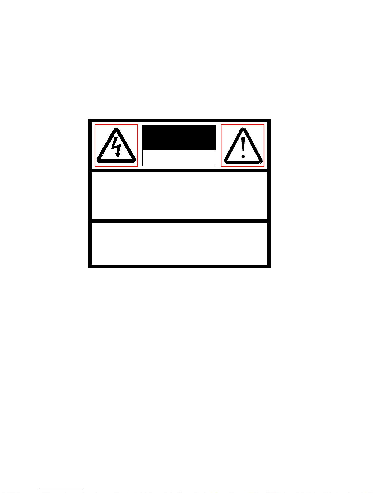
CAUTION:
RISK OF ELECTRIC SHOCK
DO NOT OPEN
Back box
Dome drive
Lower dome
Back box
Dome
Lower
8
DH—FB1
Wall mount bracket
DH—FB2
Wall mount bracket
(with 24V/3A power box)
2.3 Network Speed Dome Package
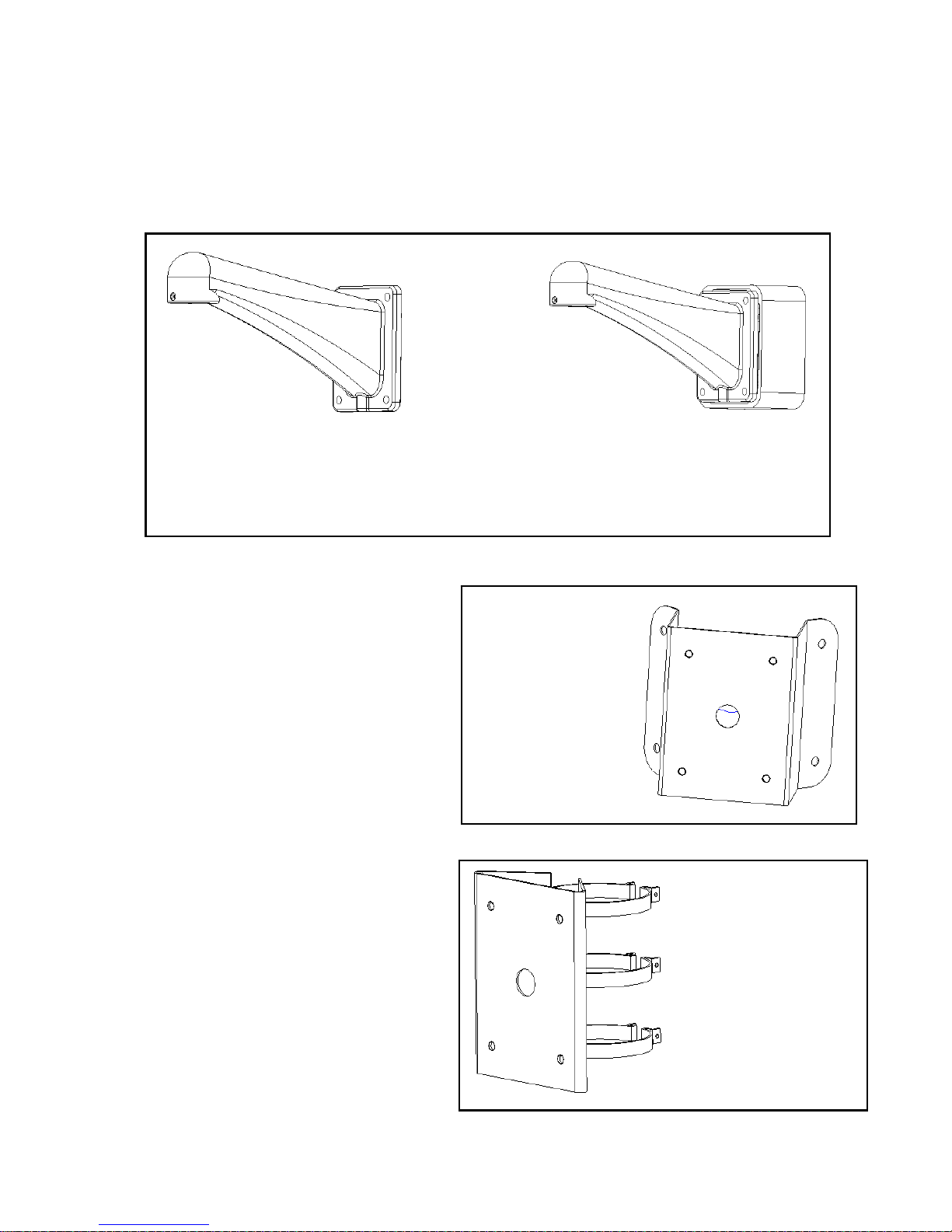
2.4 Bracket
We provide various installation brackets and installation ways for indoor and outdoor
pendent network speed dome.
1. Corner mount bracket
DH-FW corner mount bracket×1
DH-FB wall mount bracket×1(Optional)
Gasket×1
Other installation fittings
2. 装件
2. Pole mount bracket
DH-FQ pole mount bracket ×1
We provide the following dimensions:
Φ59~82mm、Φ84~108mm
Φ103~127m、Φ130~152mm
Φ155~178mm、Φ180~203mm
Φ194~216mm
DH-FB wall mount bracket×1(Optional)
Gasket×1
Other installation kit
DH—FW
Corner mount
bracket
DH—FQ
Pole mount bracket
9
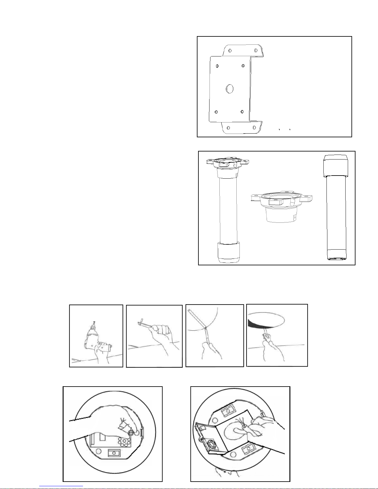
3. Wall surface mount bracket
DH-FM wall surface mount bracket×1
DH-FB wall mount bracket×1
Gasket×1
Other installation kit
4. Pendant mount bracket
DH-FD pendant fixed chassis×1
DH-FD200/500/800/1000 pendant bracket×1
(200mm /500mm/800mm/1000mm)
DH-FD stud×1
Gasket×1
Other installation kit
2.5 In-ceiling Network Speed Dome Installation
Step 1
Draw a circle in the surface and cut the circle out of the ceiling.
.
Step2
Install in-ceiling dome back box.
DH—FM
Wall surface mount
DH—FD
Pendant bracket
DH—FD
Fixed chassis
10
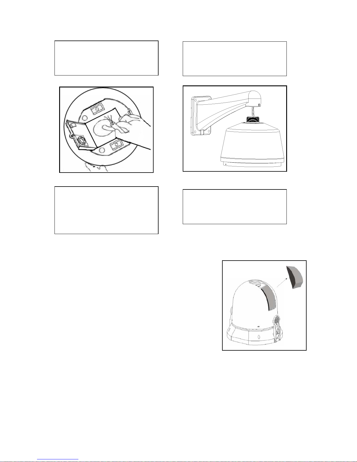
Open the hinged door to the back box.
Pull power cable, video cable, RS485 cable, network cable through cable feed out of
the conduit fittings. Connect them with PCB board.
Close the hinged door and screw the bolts.
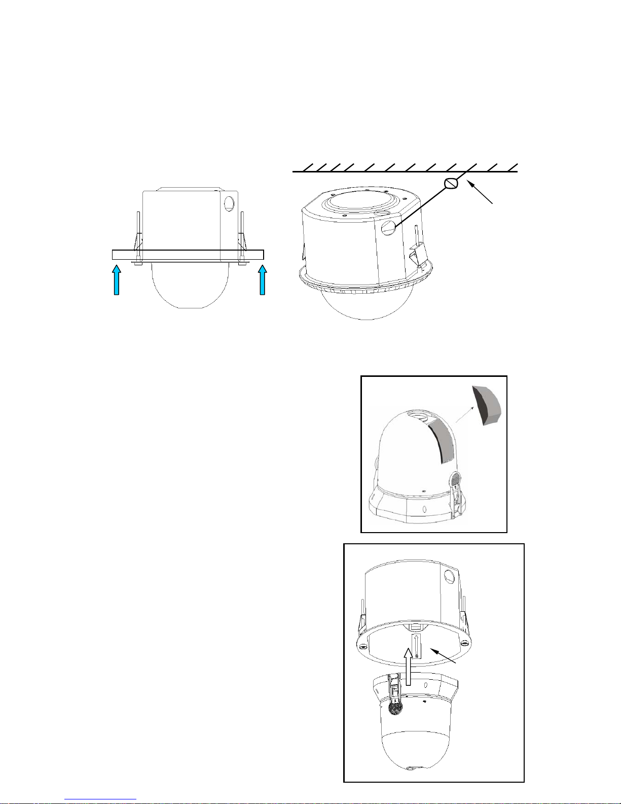
Pushing the back box into the installation hole (you just cut in step 1) by
compressing the tab lock.
Tighten the screws in the black tab locks to fix the back box in the ceiling.
Note: please install a safety chain/cable (not supplied) between the back box and the
ceiling to prevent network speed dome falling down!
Step 3
Install the dome drive.
Before installation, please take out the protective
foam and put it in a well place for future use.
Note: when you ship the network speed dome to the
manufacturer, please insert these foams to
protect the drive.
Line up the red (A) and red (B) tabs with the red
(A) and red (B) labels in the interior back box.
Push in (B) side and then the other side.
Continue pushing on the ends of the tabs until
you hear a click noise.
Note: Please make sure the clips on both sides
are firmly fixed. You can follow the tab on the
outside cover to check.
Steel safety cable
Red tab
11
Step 4
Install lower dome.
Match the two grooves of the lower dome with
the two black tab locks. Insert one side while
pressing the other side. Continue pushing on
the ends until you hear a click noise.
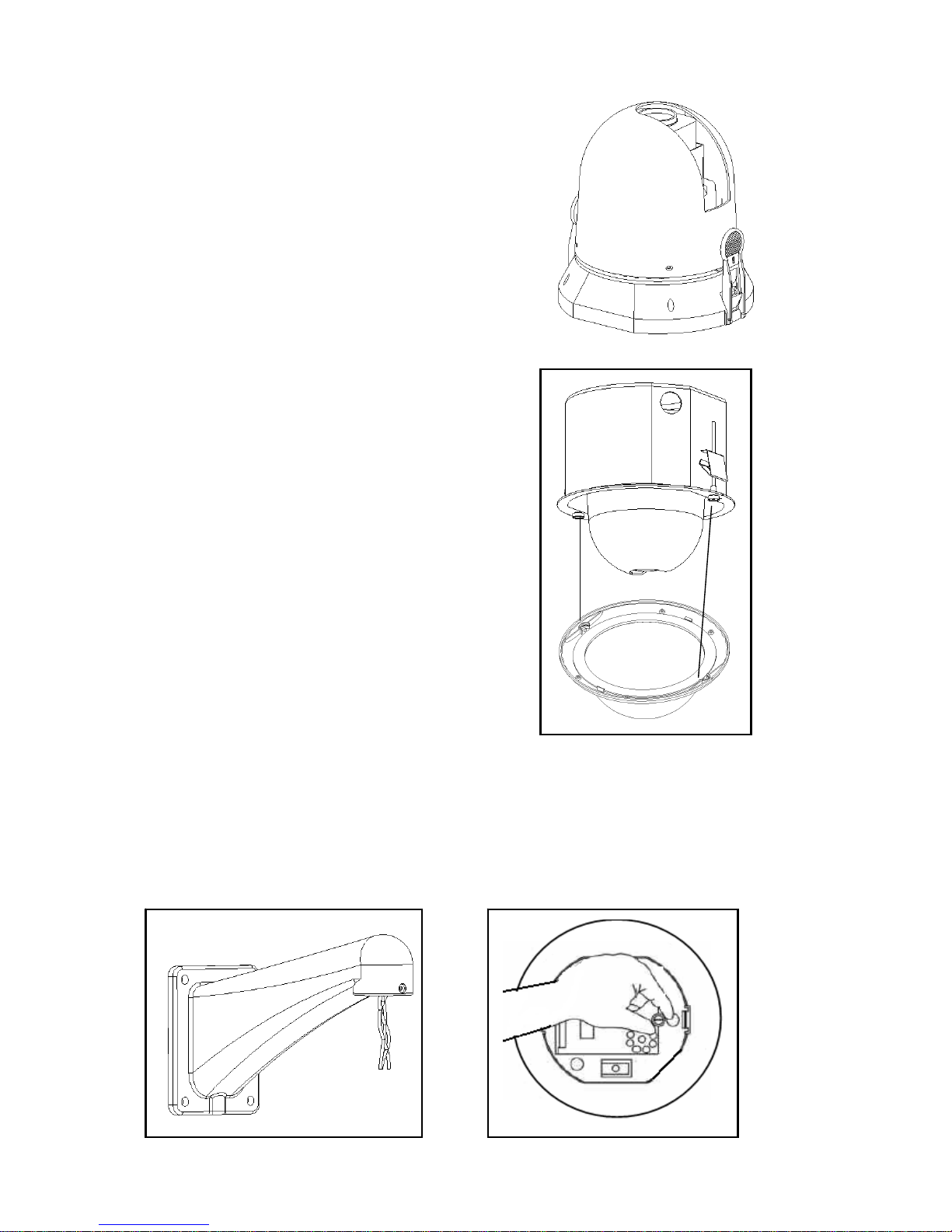
2.6 Pendant Network Speed Dome Installation
Step 1
Network speed dome back box installation
For outdoor installation series domes, please make sure the dome has sound
pressured and avoid installing in a high-temperature or humid environment.
Here are just the steps for installing the speed dome. You can refer to chapter three
for bracket installation.
12
Step 2
Connect cables
Connect power cable, video cable, RS485 and network
cable with the PCB board. Close hinged door and
screw firmly. Turn on the power, the indicate light is red.
Step 3
Install dome drive
a. Before installation, please take out the
protective foam and put it in a well place for
future use.
Note: when you ship the speed dome to the manufacturer, please insert these foams
to protect the drive.
b. Line up the red (A) and red (B) tabs with the red (A) and red (B) labels in the
interior cover. Push in (B) side and then the other side. Continue pushing on the
ends of the tabs until you hear a click noise.
A; Pull the power cable, video
cable, RS485 and network cable
through wall mount bracket hole.
B; Loosen the screws and then
open the hinged box.
C; Pull the power cable, video
cable, RS485 and network cable
through back box feed through
hole and reserve a considerable
length.
D; Refer to the above figure, use
bolts to connect bracket and the
back box.
13
Note: Please make sure the clips on both sides are firmly fixed. You can follow the
tab on the outside cover to check.
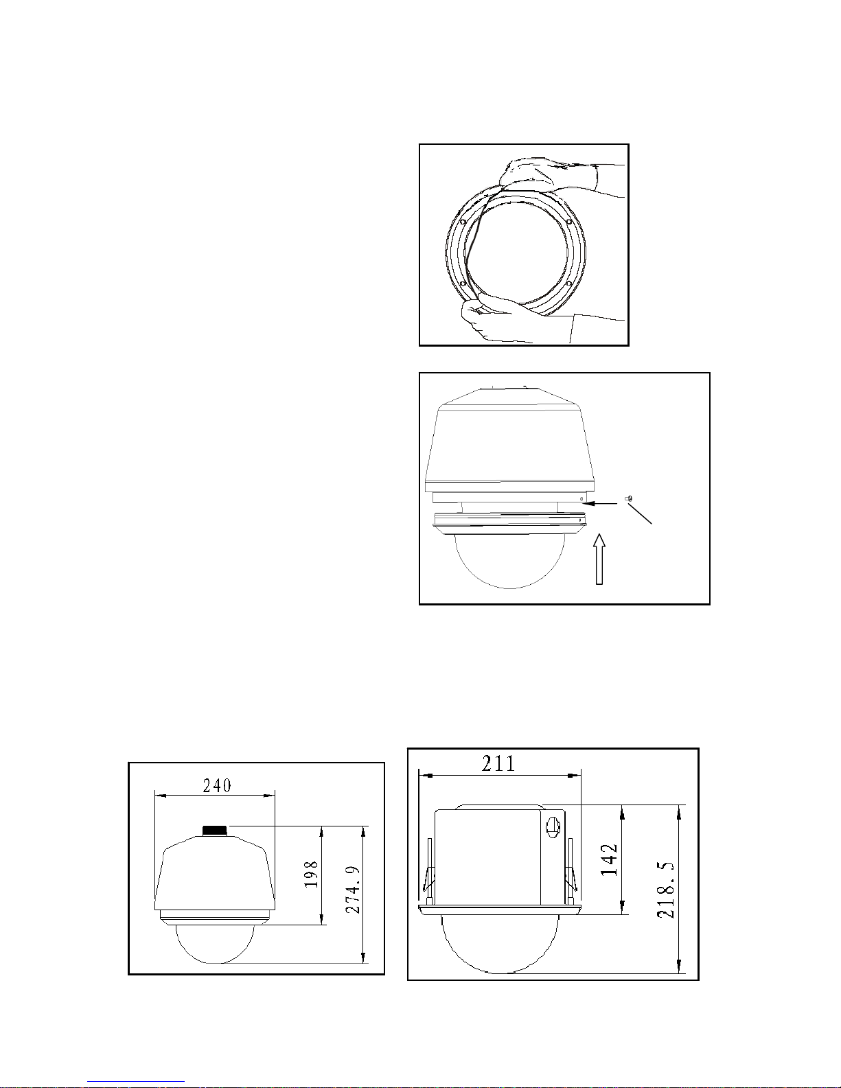
Step 4
a. Install transparent cover
Insert the silica gel ring into the
pressured groove of the lower dome.
b. Connect unfixed end of the steel
interior safety cab with the fasten end of
carriage in the lower dome.
Line up the two bolts in the carriage up
with the dome interior cover holes and
then press the transparent cover into the
dome. Screw the two stainless bolts to
fix the lower dome.
Note: please strictly follow above mentioned instructions to guarantee the
lower dome meet the IP66 waterproof level.
2.7 Network Speed Dome Installation Dimension
You can refer to the following figure for installation dimensions,
Fasten bolt
14
3 DH Network Speed Dome Bracket Installation
3.1 Important Safeguard and Warnings
All the installation here should be done by the qualified service engineer.
All the operation here should conform to local electrical safety code.
We assume no liability or responsibility for all the fires or electrical shock caused by
improper handling or installation.
3.2 Please Refer to Concerning Manual for Repair Operation.
3.3 Check accessories
After opening the package, please check and make sure the following accessories
are included in the package:
• Safety and protection material: such as transportation box foam or sponge.
• The needed fittings.
• Installation manual.
• Safety operation instructions, guarantee clauses and equipment certificate
3.4 Installation and Service after Sales
Please feel free to contact our repair and service department if you have questions.
Please keep this operating manual and case bar code for future service.
3.5 Maintenance
For safety reasons, we only recommend our clients do some simple maintenance
and cleaning work in accordance with product safety instruction and manual.
Please refer to professional service engineer for help if you need to open the cover
for repair work.
Warning
Risk of electric shock
Do not open
Caution:
Remove cover may result in electric shock or other
injuries. Please refer to professional service
engineer for help.
Warning
To prevent fire or electrical shock, do not
install this appliance in wet or moisture
environment.
 Loading...