

Page 1

C08 & C09
Network Speed Dome
Operating Manual
Page 2

2
Content
Welcome .............................................................................................................................................. 1
Important Safeguards and Warnings .............................................................................................. 2
1 Features and Functions ............................................................................................................. 3
1.1 Functions ........................................................................................................................ 3
1.1.1 Network Management ........................................................................................... 3
1.1.2 User Management ................................................................................................. 3
1.1.3 Proportional Pan and Tilt ...................................................................................... 3
1.1.4 Preset ....................................................................................................................... 3
1.1.5 Auto Scan ................................................................................................................ 3
1.1.6 Auto Touring ........................................................................................................... 3
1.1.7 Auto Pattern ............................................................................................................ 3
1.1.8 Window Blanking (privacy mask) ........................................................................ 3
1.1.9 Action on Alarm ...................................................................................................... 3
1.1.10 Storage ............................................................................................................. 4
1.1.11 Day and Night Mode ....................................................................................... 4
1.1.12 Auto Focus ....................................................................................................... 4
1.1.13 Backlight Compensation ................................................................................ 4
1.1.14 Support Zoom and PTZ Operation at the Same Time .............................. 4
1.1.15 Fast 3D Positioning ......................................................................................... 4
1.2 High Quality Components ............................................................................................ 4
1.2.1 Build-in Network Video Server ............................................................................. 4
1.2.2 Build-in Decoder ..................................................................................................... 4
1.2.3 Build-in PTZ ............................................................................................................ 4
1.2.4 High Sensitive, High Resolution Integrated Digital Color Camera ................. 5
1.3 Specification ................................................................................................................... 5
2 Network Speed Dome Installation ............................................................................................ 7
2.1 Safeguarding and Warnings ........................................................................................ 7
2.2 Preparation before Installation .................................................................................... 7
2.3 Network Speed Dome Package ................................................................................. 8
2.4 Bracket ............................................................................................................................ 8
2.5 In-ceiling Network Speed Dome Installation ............................................................. 9
2.6 Pendant Network Speed Dome Installation ............................................................ 11
Page 3

3
2.7 Network Speed Dome Installation Dimension ........................................................ 13
3 DH Network Speed Dome Bracket Installation .................................................................... 14
3.1 Important Safeguard and Warnings ......................................................................... 14
3.2 Please Refer to Concerning Manual for Repair Operation. ................................. 14
3.3 Check accessories ...................................................................................................... 14
3.4 Installation and Service after Sales .......................................................................... 14
3.5 Maintenance ................................................................................................................ 14
3.6 DH-FB Wall Mount Bracket ....................................................................................... 15
4 Network keyboard control dome ............................................................................................. 26
4.1 Dome and Network Keyboard Connection ............................................................. 26
4.2 Network Keyboard Setup before Operation ............................................................ 26
4.3 Menu and Key Introduction ....................................................................................... 26
4.4 Network Keyboard Operation .................................................................................... 27
4.4.1 Direction Setup ..................................................................................................... 28
4.4.2 Preset ..................................................................................................................... 28
4.4.3 Scan ....................................................................................................................... 28
4.4.4 Tour ........................................................................................................................ 29
4.4.5 PATTERN .............................................................................................................. 30
4.4.6 Pan Rotation ......................................................................................................... 30
5 Web client operation ................................................................................................................. 31
5.1 Network connection .................................................................................................... 31
5.2 Login and logout .......................................................................................................... 31
5.2.1 Before login ........................................................................................................... 32
5.2.2 After login .............................................................................................................. 32
5.3 Video (Right mouse menu operation) ...................................................................... 32
5.3.1 Real-time surveillance ......................................................................................... 33
5.3.2 Decode quality ...................................................................................................... 33
5.3.3 Playback control bar ............................................................................................ 33
Page 4

4
5.3.4 PTZ Control ........................................................................................................... 34
5.4 Camera setting ............................................................................................................ 36
5.4.1 Zoom ...................................................................................................................... 36
5.4.2 Focus ..................................................................................................................... 36
5.4.3 Iris ........................................................................................................................... 37
5.4.4 Preset ..................................................................................................................... 37
5.5 Auto tour ....................................................................................................................... 37
5.6 Auto scan ..................................................................................................................... 38
5.7 Auto pattern ................................................................................................................. 38
5.8 PTZ Alarm input and output setup ........................................................................... 39
5.9 Call assistant function ................................................................................................ 40
6 Other Functions in Web Menu (Configuration/Assistant) ................................................... 41
6.1 Configuration ............................................................................................................... 41
6.1.1 Load and save configuration .............................................................................. 41
6.1.2 General .................................................................................................................. 42
6.1.3 Scheduled ............................................................................................................. 43
6.1.4 Image ..................................................................................................................... 43
6.1.5 Motion Detection .................................................................................................. 45
6.1.6 Alarm ...................................................................................................................... 45
6.1.7 Video setup ........................................................................................................... 46
6.1.8 Network Setup ...................................................................................................... 47
6.2 Assistant ....................................................................................................................... 48
6.2.1 Main menu ............................................................................................................ 48
6.2.2 Change language ................................................................................................. 49
6.2.3 User manage ........................................................................................................ 49
6.2.4 Record control ...................................................................................................... 51
6.2.5 Log Information .................................................................................................... 51
6.2.6 Date Time .............................................................................................................. 52
6.2.7 System Information .............................................................................................. 52
6.2.8 Alarm prompt ........................................................................................................ 53
6.2.9 Channel name ...................................................................................................... 53
6.2.10 Upgrade BIOS ............................................................................................... 54
6.2.11 Mail Setting .................................................................................................... 54
6.2.12 Record directory ............................................................................................ 55
6.2.13 Auto Maintenance ......................................................................................... 55
6.2.14 Privacy Mask Zone ....................................................................................... 55
Page 5

1
Welcome
Thank you for purchasing our network speed dome system!
This operating manual is designed to be a reference tool for the installation and
operation of your system.
Here you can find information about this speed dome features and functions.
Before installation and operation please read the following safeguards and warnings
carefully!
Page 6

2
Important Safeguards and Warnings
1.Electrical safety
All installation and operation here should conform to your local electrical safety
codes.
We assume no liability or responsibility for all the fires or electrical shock caused by
improper handling or installation.
2.Transportation security
No heavy stress, violent vibration or water splash are allowed during transportation,
storage and installation. The camera could be damaged by improper handling.
3.Installation
Keep upwards. Handle with care.
Do not apply power to the dome before completing installation.
4.Qualified engineers needed
All installation here should be done by the qualified engineers.
All the examination and repair should be done by the qualified service engineers.
We shall not be liable for any problems caused by unauthorized modifications or
attempted repair.
6.Environment
This product has been tested and found to comply with the IP66 standard of Degrees
of protection provided by enclosure (IP Code).
The dome should be installed in a cool, dry place away from direct sunlight,
inflammable, explosive substances and etc.
7.About Camera
Camera should be installed away from direct sunlight or other strong artificial lights
to avoid blooming or smear.
Only use mild detergent or dry cloth to clean the camera.
8. About Accessories
Be sure to use all the accessories recommended by manufacturer.
Before installation, please open the package and check that all the components
listed below are included here:
z Dome
z Dome operating manual
z Bracket anchor
z Camera holder
Contact you local retailer ASAP if some thing is missing in your package.
Page 7

3
1 Features and Functions
1.1 Functions
This series network speed dome has the following functions:
1.1.1 Network Management
This series speed dome supports IE browser to realize network management. You
can implement speed dome functions via IE. Besides, its most advantage is to
realize simple operation and management via a network cable without much
peripheral equipment. You can access dome by inputting dome IP address directly.
1.1.2 User Management
System supports multiple right groups and various modifications. Each user must
belong to one group. You can set surveillance right freely when there is no login user.
System also supports several IP users visit speed dome at the same time. All the
user operations are confined by their own right limit.
1.1.3 Proportional Pan and Tilt
This function keeps the image from moving too fast when there is a large amount of
zoom. This series dome can continually decrease or increase pan and tilt speeds in
proportion to depth of zoom. When zooms speed is increasing, the camera moving
speed becomes slow. When zooms speed is decreasing, the camera moving speed
becomes fast.
1.1.4 Preset
Preset function is to save the address information (such as PTZ pan/tilt, focus and
etc) to the memory so that you can quickly adjust the dome and PTZ to the correct
position. This series speed dome supports 80 presets.
1.1.5 Auto Scan
Camera scans back and forth regularly in a horizontal field. Here you need to set left
and right limit and scan speed. You can set 5 scanning paths.
1.1.6 Auto Touring
Add addresses into a routine in a desired order and then set time and stop duration
for each address. The dome will begin an auto touring between these addresses.
You can set 8 touring paths.
1.1.7 Auto Pattern
Memorize dome operation such as pan, tilt, and zoom to repeat. Focus and iris are in
auto mode during auto pattern. For each pattern, the time should be less than 60
seconds. You can set 5 pattern paths.
1.1.8 Window Blanking (privacy mask)
Window blanking is a user-defined, four-sided section that can not be viewed by you.
The blank area will move with pan and tilt functions and automatically adjust in size
as the lens zooms.
1.1.9 Action on Alarm
This series speed dome support 2 alarm input and one relay output. Alarms can
activate PTZ movement or video record. It also supports SMS service.
Page 8

4
1.1.10 Storage
System can backup the concerning video to the central storage server via alarm or
scheduled setting as you have set. You can record in local PC and backup the video
to the client PC.
1.1.11 Day and Night Mode
Auto/manual switches in low illumination .In auto mode camera will automatically
adjust CCD light level. In manual mode you can use menu or function keys to select
day/night mode.
1.1.12 Auto Focus
Auto focus function allows the lens to remain in focus during zoom-in, zoom-out and
motion functions to get vivid image. You can use FAR or NEAR button to adjust
focus manually. System goes back to auto focus mode after pan tilt operate camera.
1.1.13 Backlight Compensation
Balance the brightest and darkest sections of a scene to produce a more vivid
picture.
1.1.14 Support Zoom and PTZ Operation at the Same Time
This series speed dome can operate zoom function during pan tilt movement, or you
can stop either of these functions (speed dome movement or zoom). During the
whole process focus and iris are in auto mode to get vivid image.
1.1.15 Fast 3D Positioning
Working with DVR, just click part of the current scene will be displayed in the central
window and automatically zooms. All of these allow you to trace precisely.
1.2 High Quality Components
This series network dome integrated the following high quality components:
1.2.1 Build-in Network Video Server
z NVS compress and decode video data to the terminal via network
z Maximally support 8 to 10 connections at the same time
z Support HTTP、TCP、UDP、MULTICAST、RTP/RTCP
z Alarm data and information via SMTP
z Support WEB visit suitable for WAN
z Network dome configuration management and authentication via Ethernet
z Support IP address dynamic allocation
1.2.2 Build-in Decoder
All digital design, memorize all data on connecting plate, which guarantees data
safety once power supply failure occurred.
z Integrated design, high reliability.
z 80 presets (in English or Chinese). Support 8 auto tours.
z 5 auto scan
z 5 auto pattern
z Support RS485 control
z Maximally support 8 privacy mask zones
z Support multiple-protocol and various baud rates
1.2.3 Build-in PTZ
z Stepper motor running smoothly and sensitively, locate accurately
z Integrated design, compact conformation
Page 9

5
z Delicate engine drive. Support 360 º continuous pan rotation. No blind area.
z Support 0.1º /s pan rotate while maintain image stability
z 180 º continuous tilt surveillance.
1.2.4 High Sensitive, High Resolution Integrated Digital Color Camera
z Auto focus
z Auto backlight compensation
z Auto light control
z Auto white balance
z Auto day/night mode
1.3 Specification
Power
AC 24V/3A(±20%)(include temperature control
circuit)
Core Consumption
15W
Heater
Consumption
35W
Decode Card
Build-in
Network Video
Server
Build-in
Engine
stepper motor
Preset
80
Auto Cruise
8
Auto Scan
5
Auto Pattern
5
Image Quality
Six levels (Optional)
Alarm Input/Output
2/1
Video Display
One-window display mode
Signal Format
PAL:625 TV Line, 50F/S
NTSC:525 TV Line, 60F/S
Resolution
D1、HD1、CIF、QVGA、QCIF
Compression
MPEG-4 CBR、MPEG-4 VBR
Video Speed
Rea-time mode:
Pal:1-25f/s
NTSC:1-30f/s
Alarm Relay
30VDC 1A ,125V 0.5A
Auto Lens
Adjust speed in accordance with lens
Auto Rotation
Vertical 90º rotates to horizontal 180 º
Auto Pan Scan
360º continuously
Manual Pan Motion
Speed
0.1º—120º/S
Preset Maximum
Speed
300º
Manual Tilt Motion
0.1º—90º/S
Manual Tilt Scan
Section
0º—180º
Page 10
6
Control Mode
Network
Baud Rate
1200/2400/4800/9600 (Optional)
PTZ Scan Accuracy
0.06 ± 0.015º
S/N Ratio
> 50dB
Effective Pixel
752(H)× 582(V)
Horizontal
Resolution
480TVL
Fan and Heater
Auto/Manual (Default mode: auto)
Humidity
<90%
Environment
-30—55(Outdoor. Pre-heat needed) -10—50
(Indoor)
Page 11

7
2 Network Speed Dome Installation
2.1 Safeguarding and Warnings
Before installation and operation, please read the following safety warnings carefully!
z All the installation here should be done by the qualified service engineer.
z All the operation here should conform to your local electrical safety code.
z The indoor series dome shall not be installed in wet or moisture environment.
z After reinstallation or repair work, please check the electric resistance between
circuits and network speed dome. You should guarantee sound insulation.
z The stuff used to sustain should support at least four times of that of speed dome.
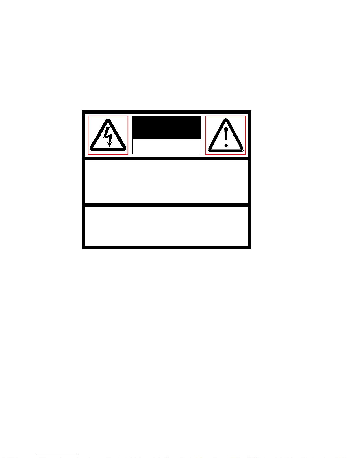
These symbols means there is a risk of electric shock.
This symbol means you should follow the important instructions to operate or
maintenance.
2.2 Preparation before Installation
These series network speed domes are divided into two types: in-ceiling network
speed dome and pendant network speed dome.
Please contact your local retailer if something is missing or damaged in your
package.
Pendant Series Fittings In-ceiling Series Fittings
CAUTION:
RISK OF ELECTRIC SHOCK
DO NOT OPEN
Back box
Dome drive
Lower dome
Back box
Dome
Lower
Page 12
8
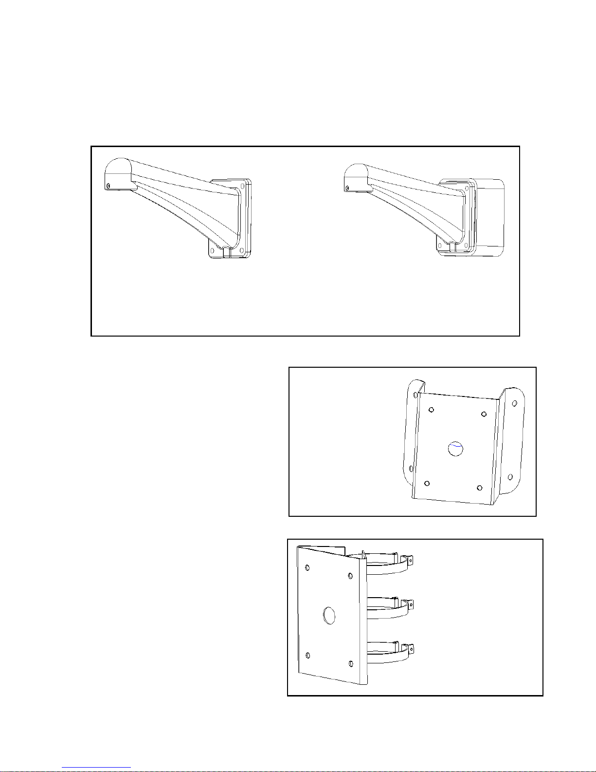
DH—FB1
Wall mount bracket
DH—FB2
Wall mount bracket
(with 24V/3A power box)
2.3 Network Speed Dome Package
2.4 Bracket
We provide various installation brackets and installation ways for indoor and outdoor
pendent network speed dome.
1. Corner mount bracket
DH-FW corner mount bracket×1
DH-FB wall mount bracket×1(Optional)
Gasket×1
Other installation fittings
2. 装件
2. Pole mount bracket
DH-FQ pole mount bracket ×1
We provide the following dimensions:
Φ59~82mm、Φ84~108mm
Φ103~127m、Φ130~152mm
Φ155~178mm、Φ180~203mm
Φ194~216mm
DH-FB wall mount bracket×1(Optional)
Gasket×1
Other installation kit
DH—FW
Corner mount
bracket
DH—FQ
Pole mount bracket
Page 13
9
3. Wall surface mount bracket
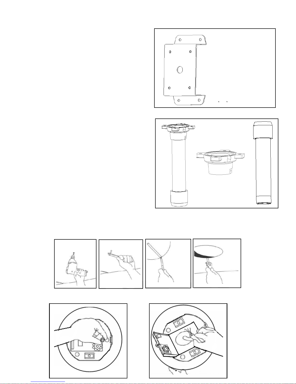
DH-FM wall surface mount bracket×1
DH-FB wall mount bracket×1
Gasket×1
Other installation kit
4. Pendant mount bracket
DH-FD pendant fixed chassis×1
DH-FD200/500/800/1000 pendant bracket×1
(200mm /500mm/800mm/1000mm)
DH-FD stud×1
Gasket×1
Other installation kit
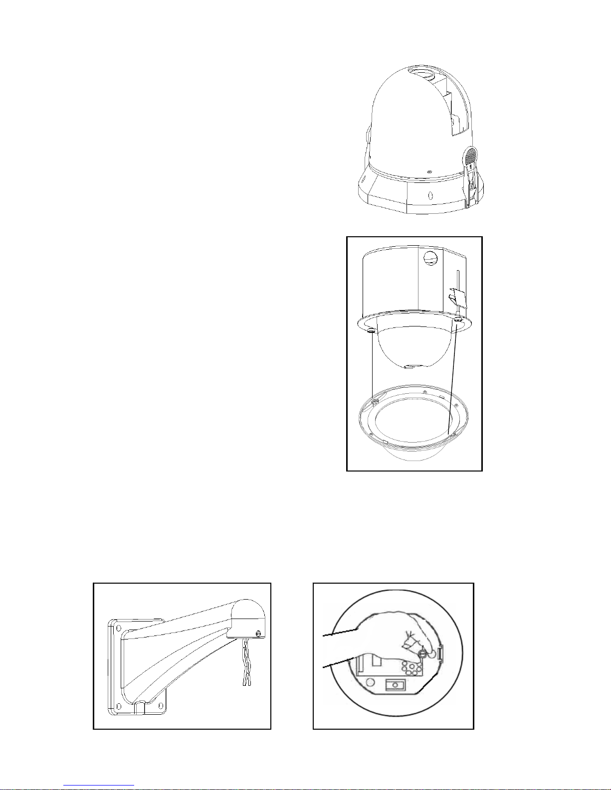
2.5 In-ceiling Network Speed Dome Installation
Step 1
Draw a circle in the surface and cut the circle out of the ceiling.
.
Step2
Install in-ceiling dome back box.
DH—FM
Wall surface mount
DH—FD
Pendant bracket
DH—FD
Fixed chassis
Page 14
10
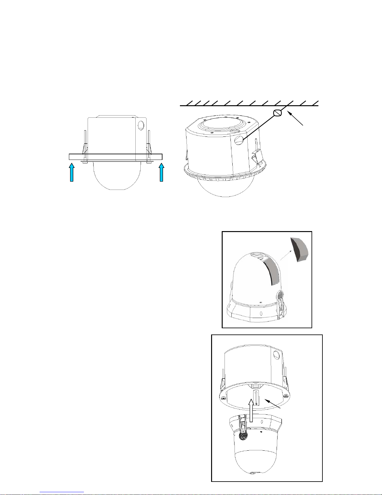
Open the hinged door to the back box.
Pull power cable, video cable, RS485 cable, network cable through cable feed out of
the conduit fittings. Connect them with PCB board.
Close the hinged door and screw the bolts.
Pushing the back box into the installation hole (you just cut in step 1) by
compressing the tab lock.
Tighten the screws in the black tab locks to fix the back box in the ceiling.
Note: please install a safety chain/cable (not supplied) between the back box and the
ceiling to prevent network speed dome falling down!
Step 3
Install the dome drive.
Before installation, please take out the protective
foam and put it in a well place for future use.
Note: when you ship the network speed dome to the
manufacturer, please insert these foams to
protect the drive.
Line up the red (A) and red (B) tabs with the red
(A) and red (B) labels in the interior back box.
Push in (B) side and then the other side.
Continue pushing on the ends of the tabs until
you hear a click noise.
Note: Please make sure the clips on both sides
are firmly fixed. You can follow the tab on the
outside cover to check.
Steel safety cable
Red tab
Page 15
11
Step 4
Install lower dome.
Match the two grooves of the lower dome with
the two black tab locks. Insert one side while
pressing the other side. Continue pushing on
the ends until you hear a click noise.
2.6 Pendant Network Speed Dome Installation
Step 1
Network speed dome back box installation
For outdoor installation series domes, please make sure the dome has sound
pressured and avoid installing in a high-temperature or humid environment.
Here are just the steps for installing the speed dome. You can refer to chapter three
for bracket installation.
Page 16
12
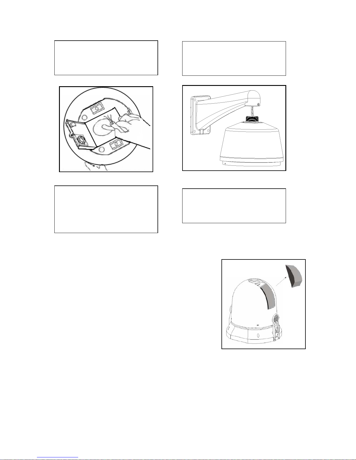
Step 2
Connect cables
Connect power cable, video cable, RS485 and network
cable with the PCB board. Close hinged door and
screw firmly. Turn on the power, the indicate light is red.
Step 3
Install dome drive
a. Before installation, please take out the
protective foam and put it in a well place for
future use.
Note: when you ship the speed dome to the manufacturer, please insert these foams
to protect the drive.
b. Line up the red (A) and red (B) tabs with the red (A) and red (B) labels in the
interior cover. Push in (B) side and then the other side. Continue pushing on the
ends of the tabs until you hear a click noise.
A; Pull the power cable, video
cable, RS485 and network cable
through wall mount bracket hole.
B; Loosen the screws and then
open the hinged box.
C; Pull the power cable, video
cable, RS485 and network cable
through back box feed through
hole and reserve a considerable
length.
D; Refer to the above figure, use
bolts to connect bracket and the
back box.
Page 17
13
Note: Please make sure the clips on both sides are firmly fixed. You can follow the
tab on the outside cover to check.
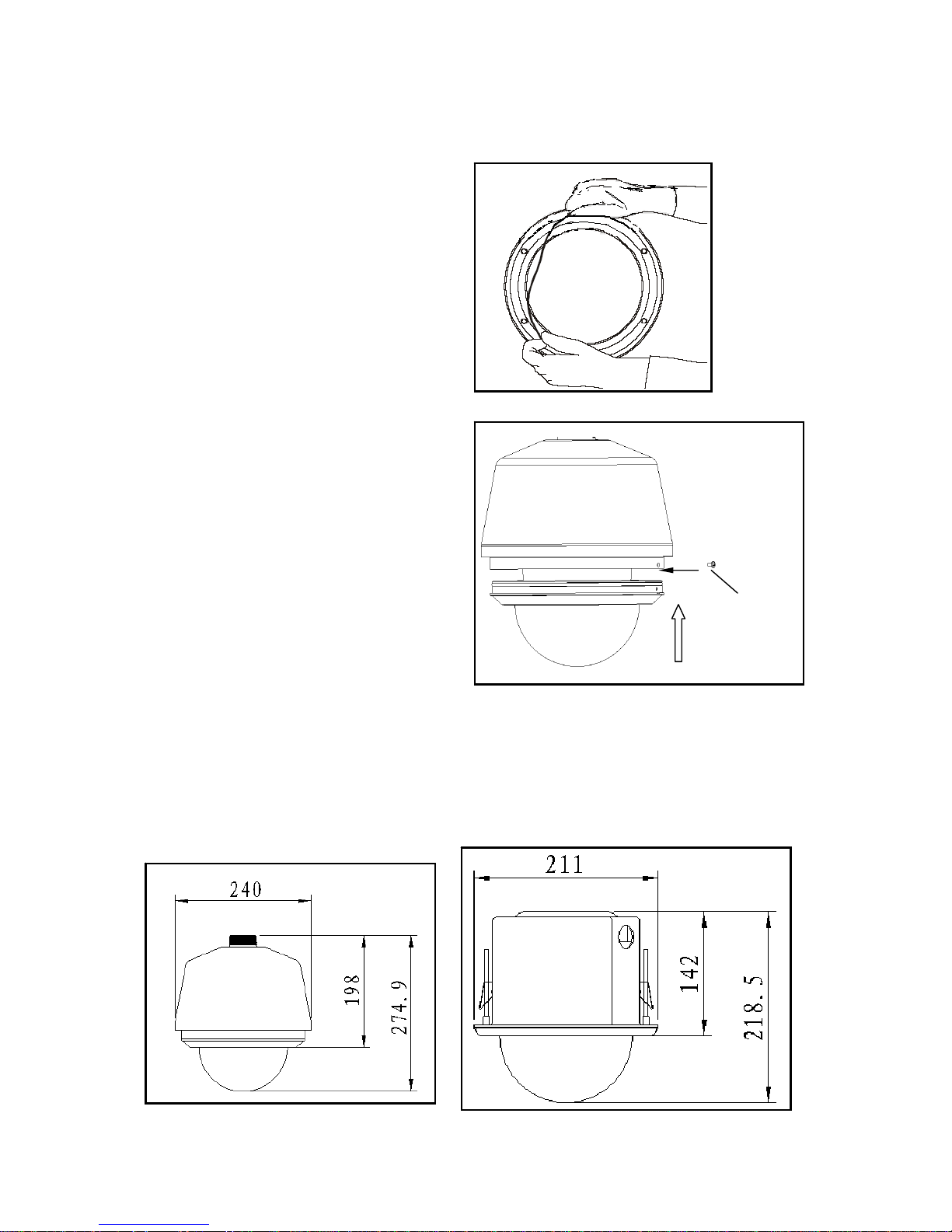
Step 4
a. Install transparent cover
Insert the silica gel ring into the
pressured groove of the lower dome.
b. Connect unfixed end of the steel
interior safety cab with the fasten end of
carriage in the lower dome.
Line up the two bolts in the carriage up
with the dome interior cover holes and
then press the transparent cover into the
dome. Screw the two stainless bolts to
fix the lower dome.
Note: please strictly follow above mentioned instructions to guarantee the
lower dome meet the IP66 waterproof level.
2.7 Network Speed Dome Installation Dimension
You can refer to the following figure for installation dimensions,
Fasten bolt
Page 18
14
3 DH Network Speed Dome Bracket Installation
3.1 Important Safeguard and Warnings
All the installation here should be done by the qualified service engineer.
All the operation here should conform to local electrical safety code.
We assume no liability or responsibility for all the fires or electrical shock caused by
improper handling or installation.
3.2 Please Refer to Concerning Manual for Repair Operation.
3.3 Check accessories
After opening the package, please check and make sure the following accessories
are included in the package:
• Safety and protection material: such as transportation box foam or sponge.
• The needed fittings.
• Installation manual.
• Safety operation instructions, guarantee clauses and equipment certificate
3.4 Installation and Service after Sales
Please feel free to contact our repair and service department if you have questions.
Please keep this operating manual and case bar code for future service.
3.5 Maintenance
For safety reasons, we only recommend our clients do some simple maintenance
and cleaning work in accordance with product safety instruction and manual.
Please refer to professional service engineer for help if you need to open the cover
for repair work.
Warning
Risk of electric shock
Do not open
Caution:
Remove cover may result in electric shock or other
injuries. Please refer to professional service
engineer for help.
Warning
To prevent fire or electrical shock, do not
install this appliance in wet or moisture
environment.
Page 19
15
When you need to return network speed dome for repair job, please get the repair
number first and ship the product to the factory in accordance with transportation
safety code.
We assume no liability for all the damages result from improper package during
transportation.
To reduce the risk of fire or electrical shock, do not remove the cover.
All the repair work should be done by the professional engineers.
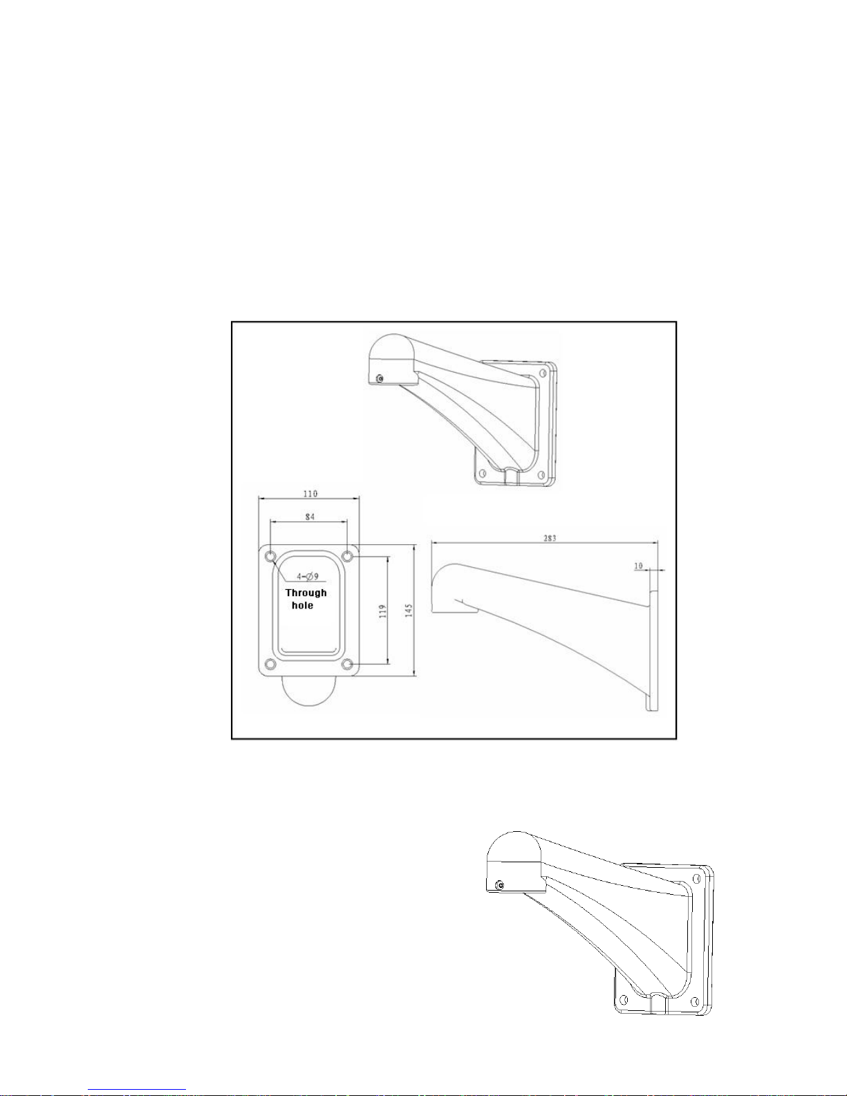
3.6 DH-FB Wall Mount Bracket
It is suitable for indoor and outdoor pendant series dome. It can work with exterior
corner bracket, wall mount bracket and pole bracket.
DH-FB wall mount bracket
Please make sure all the fittings are included in the package, contact your local
retailers immediately if something is missing.
1. DH-FB wall mount bracket
It is suitable for indoor and outdoor pendant
dome
It works with corner bracket, wall mount bracket
and pole bracket.
Page 20
16
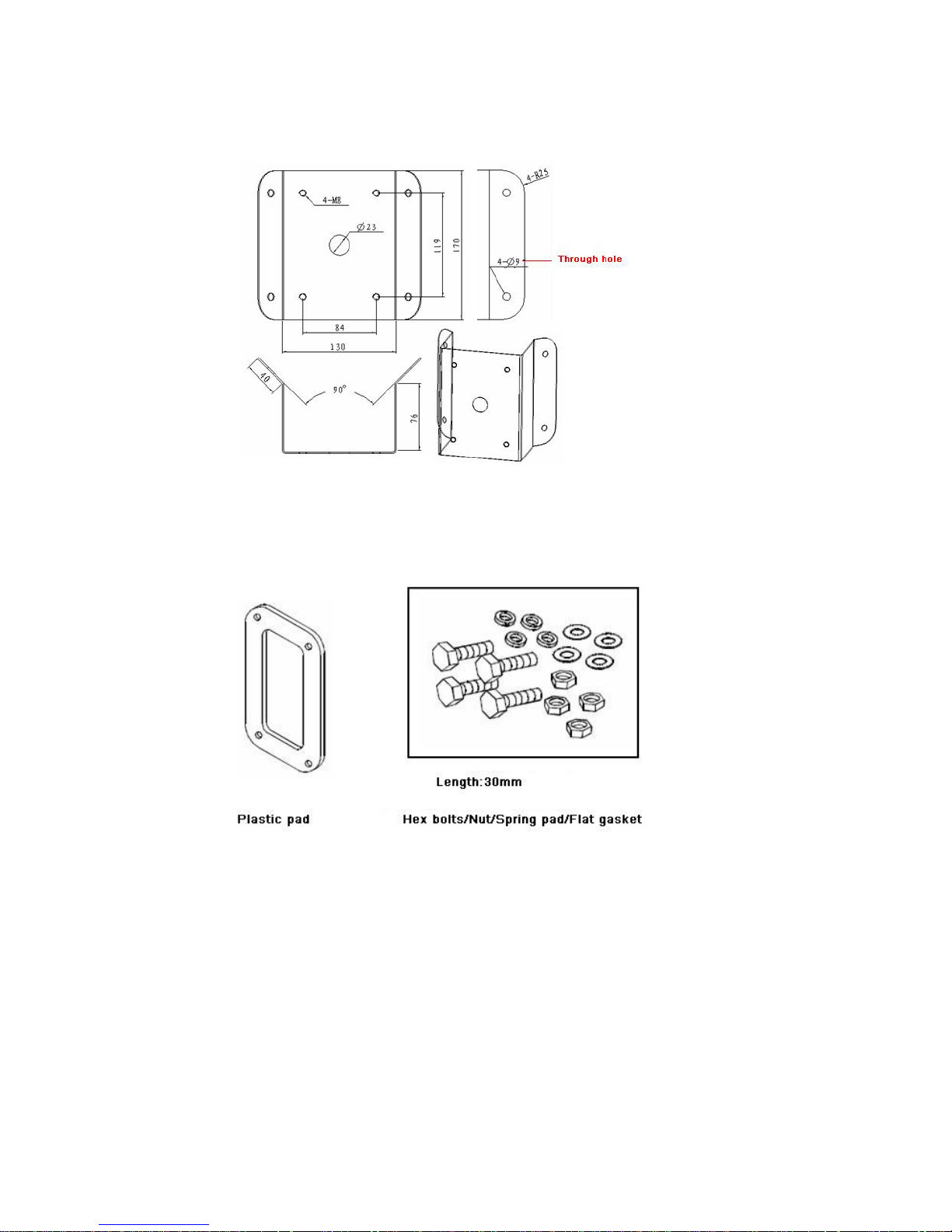
2. DH-FW exterior corner bracket
It works with wall mount bracket for corner installation.
3. DH-FB wall mount bracket fittings
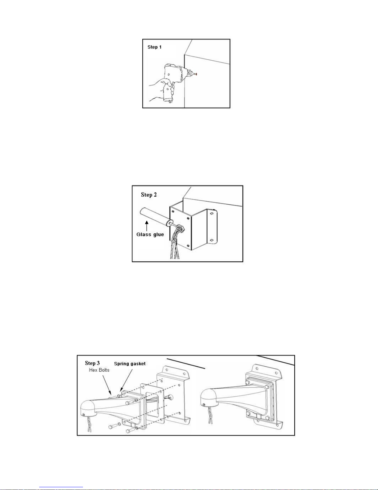
Step1-Dig holes in the wall
Dig four holes in the wall in accordance with corner bracket holes and then insert φ
expansion bolts into the hole (not supplied).
Page 21
17
Step 2-Corner bracket installation
Connect power cable, video signal cable, control cable and network cable through
the corner bracket hole. Insert corner bracket holes into the four expansion blots and
use screw cap and gasket to fasten firmly.
Wipe glass glue (not supplied) in the string hole to enhance waterproof capability.
(Please make sure the cable is long enough to pull through the hole)
Step 3-Fitting installation
Screw four hex bolts through corner mount bracket and plastic gasket into wall
mount bracket. (Between screw and bracket, please add a spring gasket). Fasten
the wall bracket firmly mount the corner bracket.
Note: when screw bolts, please fasten the spring gasket and then turn half a circle.
In this way, you can fasten plastic gasket to get sound airproof ability and at the
same time to avoid screw damage.
Page 22
18
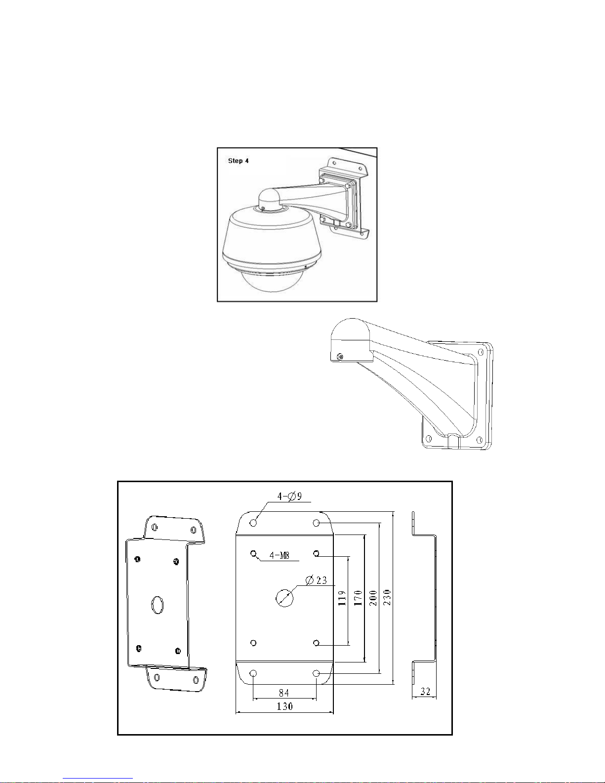
Step 4- Network Speed Dome installation
Open the dome hinged box and connect cables into the dome. Please refer to
chapter two for network speed dome installation.
Please check all the following fittings are included in the package, contact your local
retailer immediately if something is missing.
1. DH-FB wall mount bracket
It is suitable for indoor and outdoor pendant
dome
It works with corner mount bracket, wall mount
bracket and pole bracket.
2. DH-FM wall surface mount bracket
It should work with wall mount bracket for wall surface installation.
Page 23
19
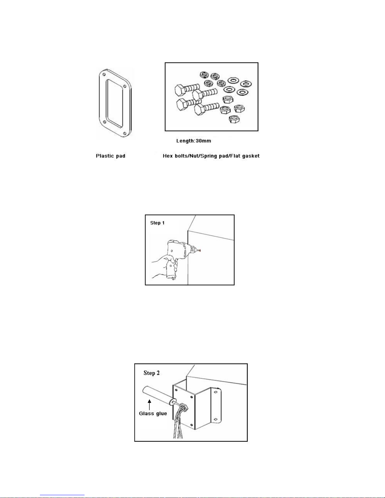
3. DH-FB wall mount bracket fittings
Step 1-Dig holes in the wall
Dig four holes in the wall in accordance with corner mount bracket hole and insert φ
expansion bolts (not supplied) into the hole.
Step 2-Corner mount bracket installation
Connect power cable, video signal cable, control cable and network cable through
the corner bracket hole. Insert corner bracket holes into the four expansion blots and
use screw cap and gasket to fasten firmly.
Wipe glass glue (not supplied) in the string hole to enhance waterproof capability.
(Please make sure the cable is long enough to pull through the hole)
Page 24
20
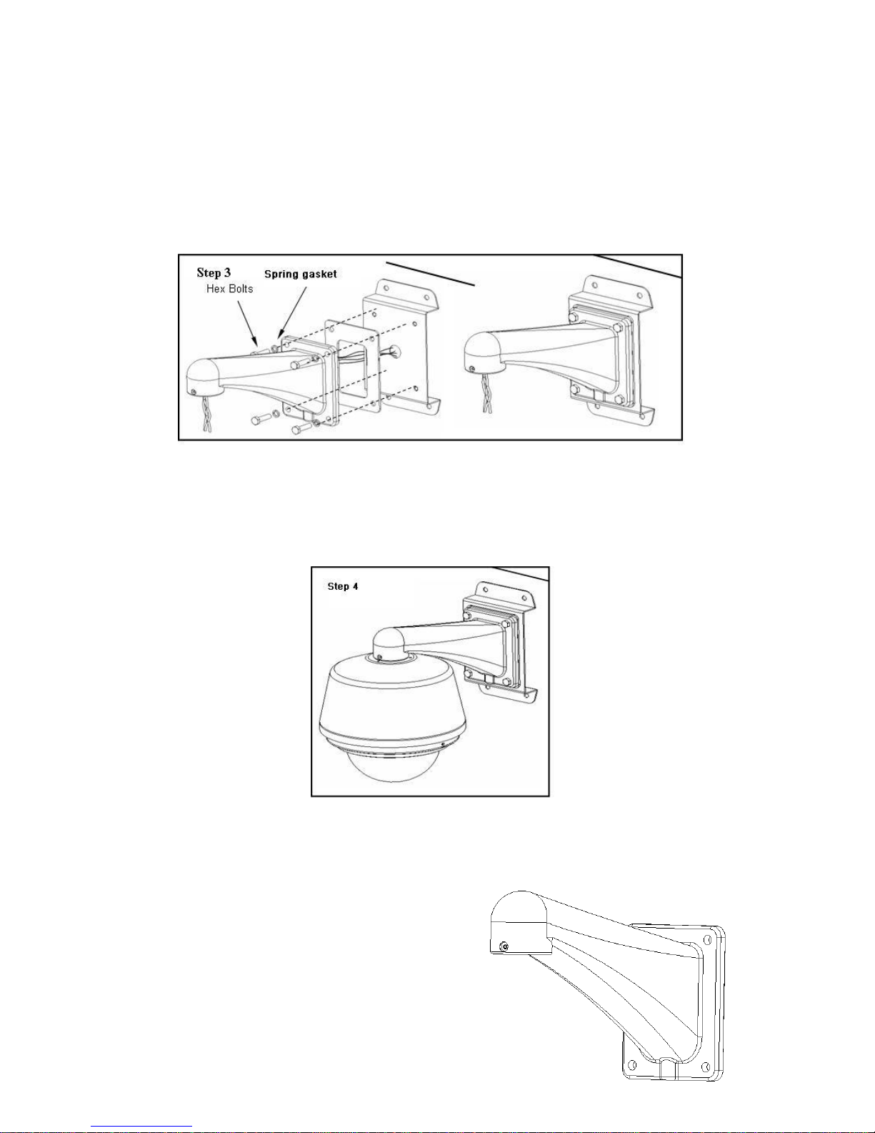
Step 3-Fitting installation
Screw four hex bolts through wall mount bracket and plastic gasket into wall surface
mount bracket. (Between screw and bracket, please add a spring gasket). Fasten
the wall bracket firmly mount the corner bracket.
Note: when screw bolts, please fasten the spring gasket and then turn half a circle.
In this way, you can fasten plastic gasket to get sound airproof ability and at the
same time to avoid screw damage.
Step 4-Network Speed Dome Installation
Open the dome hinged box and connect cables into the dome. Please refer to
chapter two for network speed dome installation.
Please check all the following fittings are included in the package, contact you local
retailer immediately if something is missing.
1. DH-FB wall mount bracket
It is suitable for indoor and outdoor pendant
dome. It works with corner mount bracket, wall
mount bracket and pole mount bracket.
Page 25
21
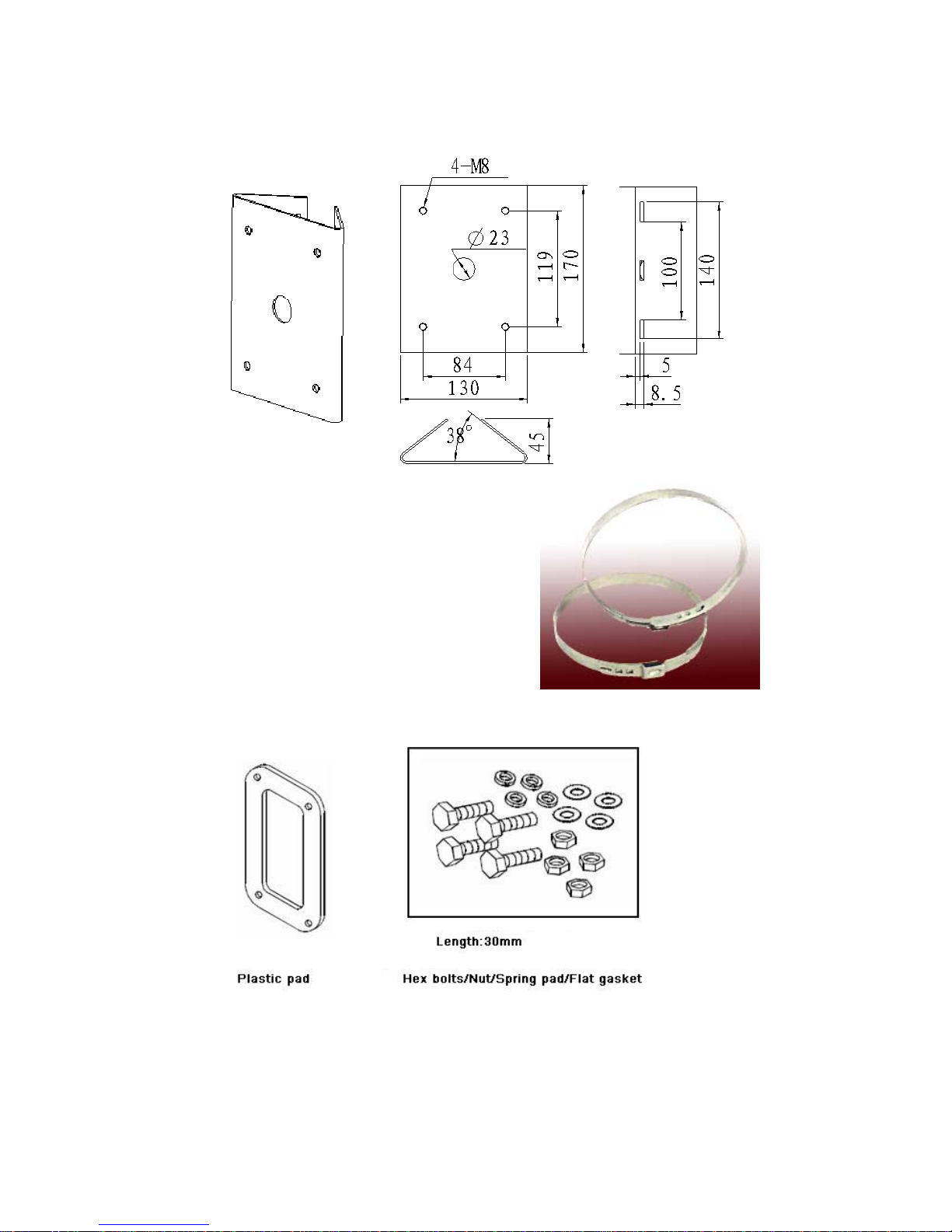
2. DH-FQ pole mount bracket
It works with wall mount bracket for pole mount installation.
It works with pole mount bracket and diameter is
adjustable. There are seven dimensions for you.
Φ59 - 82mm, Φ84 -108mm
Φ103 -127mm, Φ130 -152mm
Φ155 -178mm, Φ180 -203mm
Φ194 -216mm
We also supply customized dimensions.
3. DH-FB wall mount fitting installation
Step 1-Pole bracket combination
Use slotted screwdriver to open three straps of the pole and connect them through
the bracket holes.
Page 26
22
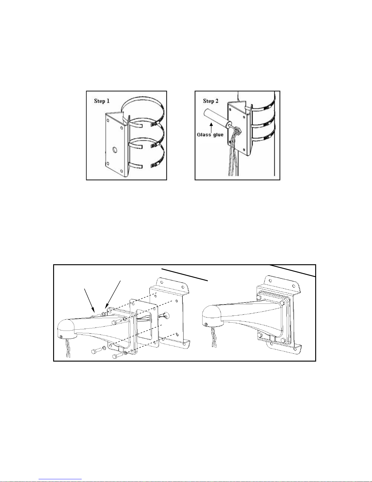
Step 2-Corner bracket installation
Connect control cable, video cable, power cable and network cable through the
bracket centre hole. Get the three straps to fasten the column object and screw the
bolts firmly. Wipe glass glue (not supplied) at the string holes to enhance waterproof
ability.
Step 3-Fitting installation
Screw four hex bolts through wall mount bracket and plastic gasket into pole mount
bracket. (Between screw and bracket, please add a spring gasket). Fasten the wall
mount bracket firmly on the pole mount bracket.
Note: when screw bolts, please fasten the spring gasket and then turn half a circle.
In this way, you can fasten plastic gasket to get sound airproof ability and at the
same time to avoid screw damage.
Step 4-Dome installation
Step 4- Dome Installation
Open the dome hinged box and connect cables into the dome. Please refer to
chapter two for network speed dome installation.
Please make sure all the following fittings are included in the package, contact you
local retailer immediately if something is missing.
Spring
Hex Bolts
Step 3
Page 27
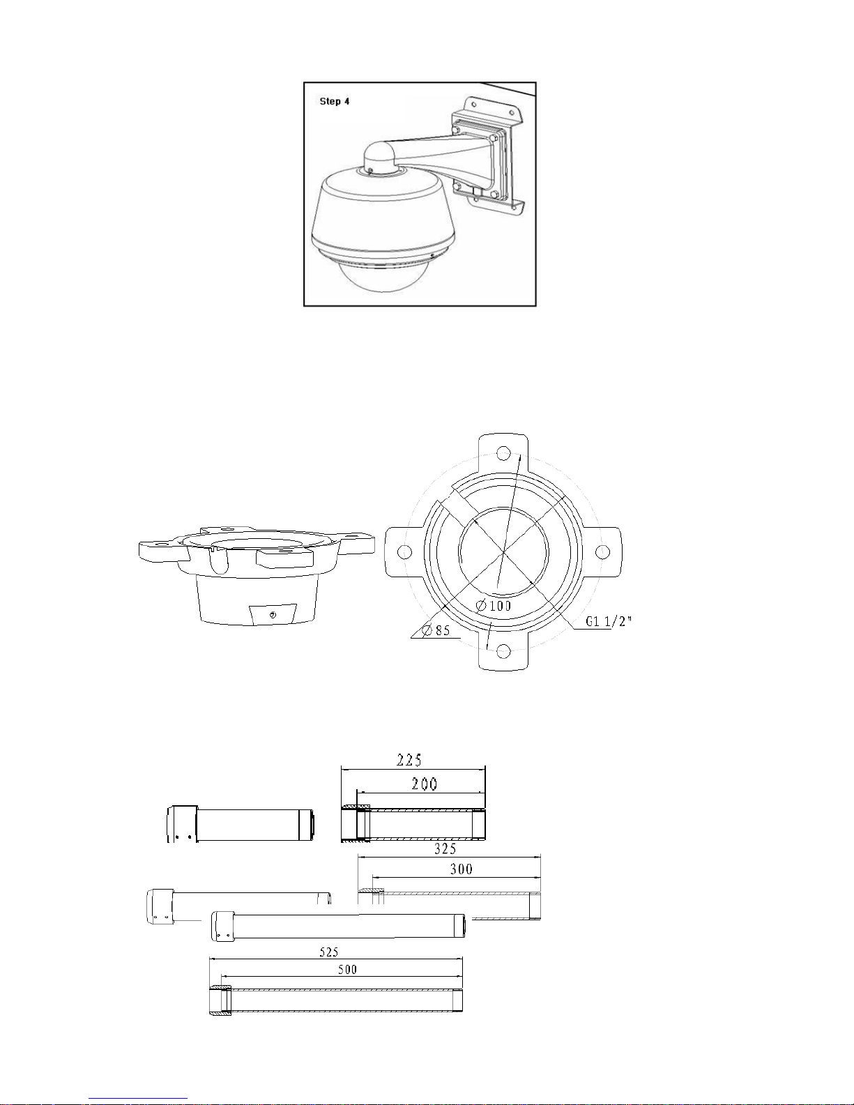
23
1. DH-FD pendant bracket chassis(with string groove)
It is suitable for pendant back box installation. It works with pendant bracket.
2. DH-FD200/300/500 connection rod
DH-FD200 length 200mm;DH-FD300 length 300mm;DH-FD500 length 500mm,
Pendant bracket should work with pendant fixed chassis. (Standard configuration)
Page 28
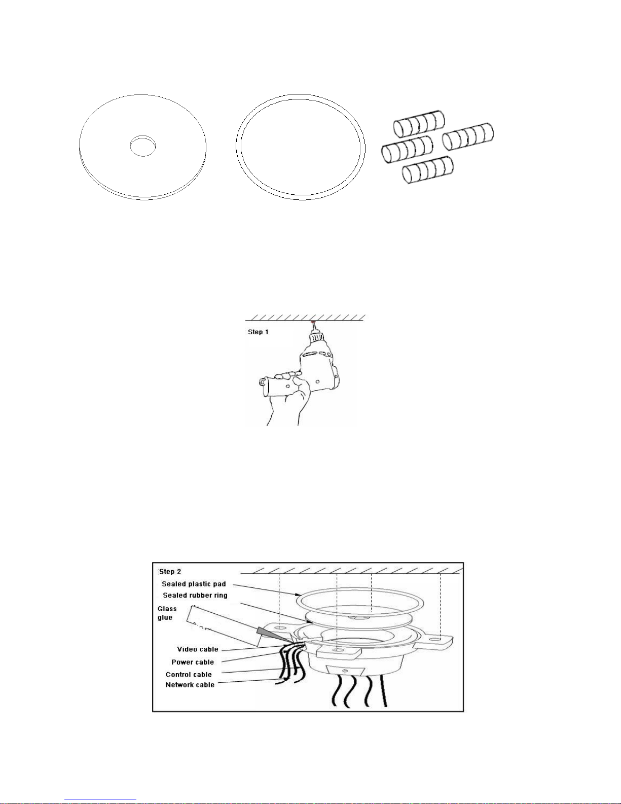
24
3. DH-FD suspended bracket fittings
Step 1-Dig four holes in the wall
Draw four Φ6 holes (not supplied) in the wall in accordance with holes of fixed
chassis and then insert Φ6 expansion bolts into the holes.
Step 2-Pendant bracket connection chassis installation
Connect control cable, video cable, power cable and network cable through the
chassis centre hole. Fasten rubber pad on the suspended chassis. Insert the chassis
four holes into expansion bolts and use screw cap and gasket to fix firmly. Wipe
glass glue (not supplied) at the string holes to enhance waterproof ability.
Note: please make sure the cable is long enough to pull through the hole.
Step 3-Suspended bracket installation
Sealed plastic pad
Sealed rubber ring
Set screw
Page 29
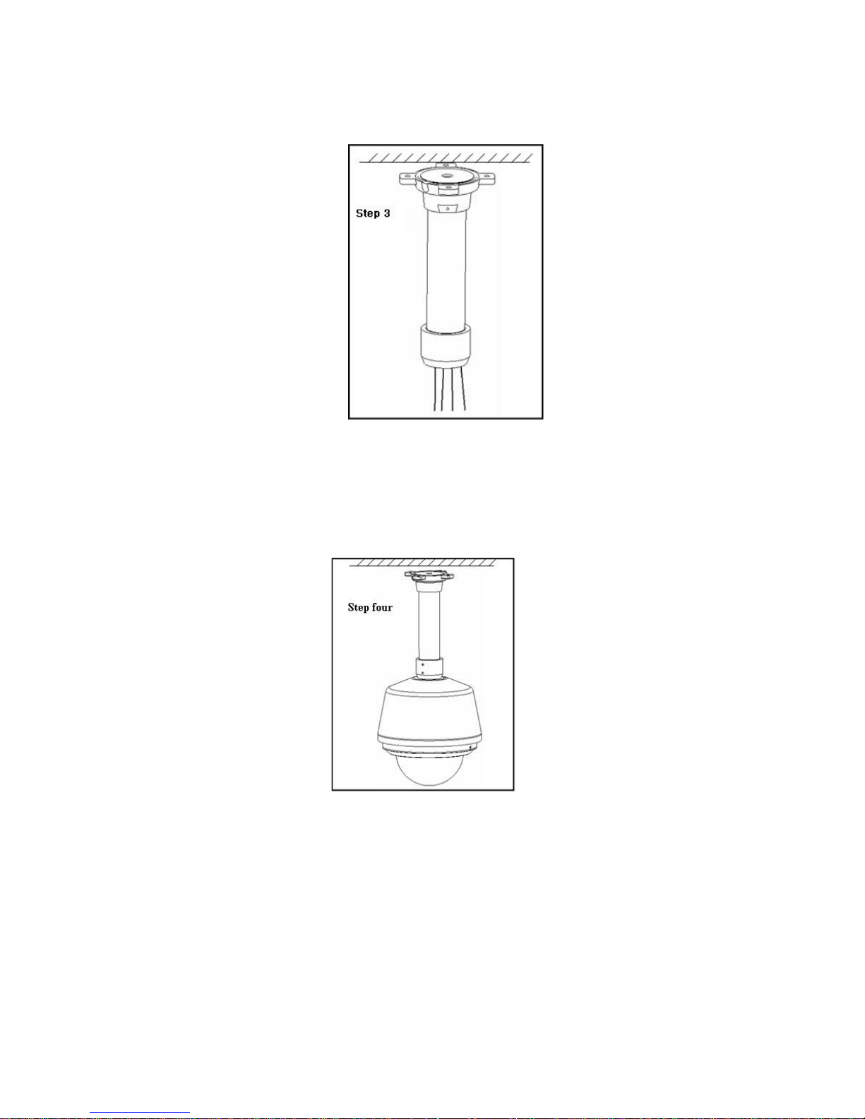
25
Connect the cables through the bracket centre, and circle the pendant bracket into
the fixed chassis. Use one slot to fasten the screw firmly.
Note: please add anaerobic adhesive to the screw for outdoor use.
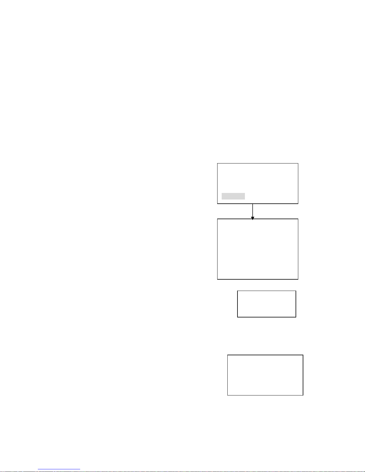
Step 4-Network dome installation
Open the dome hinged box and connection cables into the dome. Please refer to
chapter two for network speed dome installation.
Page 30
26
Current device:dome
IP:192.168.1.108
Connecting
ID 号:0
4 Network keyboard control dome
Note: all the operations here are based on DH-SD protocol. You can refer to
Chapter eight for PELCO protocol operation.
4.1 Dome and Network Keyboard Connection
Connect dome A cable with Pin 3 or Pin 7 of Keyboard 485 interface. Connect dome
B cable with Pin 8 or Pin 9 of Keyboard 485 Port.
4.2 Network Keyboard Setup before Operation
Before setup please make sure:
• Keyboard and dome cable connections are right.
• Connect dome with power source.
• From menu operation to control point to ser properly.
When you click ESC, system pops up a warning dialogue.
Click ENTER to save setup or click ESC to exit.
Note: all the items listed here should be properly set. ID, device name, serial port
and IP are all unique.
4.3 Menu and Key Introduction
Click ID and then input network speed dome ID, system
goes to current device connection dialogue box.
Click MENU system pops up a dialogue. You can use this
menu to work with dome menu.
Please refer to the following sheet for operation keys.
ID:*0
Device name: ①
Device type:Dome
Connection:Network connection
Control Point IP:192.168.1.108
Control point port:37777
Protocol:DH-1
Here is for you to set ID, device
name and device type. Click ID to go
to current device connection
interface.
Move cursor to highlight “connection”
and then click ENTER. System goes to
network connection setup. Control point
IP is network speed dome address,
control point port is 37777, select
protocol as DH-1
After all the setup, please click ENTER to
save modification.
Save Data?
Yes: ENTER, No:ESC
Page 31

27
Key
Enter
dome
menu
MENU
Move
cursor
up
↑
Move
cursor
down
↓
ON/OFF
or select
other
function
← or →
Enter
sub
menu
ENTER
Exit sub
menu
Highlight BACK and then click
ENTER in keyboard.
Exit
dome
menu
•
Click ESC in the keyboard.
• Highlight EXIT and then click
ENTER in the keyboard.
Please refer to the following sheet for keyboard function.
Key Function
MENU
Dome menu shortcut
SCAN
Pop up scan menu
AUTO-PAN
Pop up tour menu
PATTERN
Pop up pattern menu
SET
Pop up preset menu
GOTO
System goes to preset menu
REMOVE
Pop up delete preset menu
P/T
PTZ setup shortcut menu
TELE
Lens zoom out
WIDE
Lens zoom out
NEAR
PTZ focus zoom in.
FAR
PTZ focus zoom out
CLOSE
PTZ iris zoom out
OPEN
PTZ iris zoom in
WIPER
Shortcut key to control dome rain
brush
LIGHT
Shortcut key to control dome light
4.4 Network Keyboard Operation
Note:
• “X” scope may not be the same due to multiple protocols.
• Use up/down keys to control dome menu.
• Use left/right keys to move cursor.
Page 32
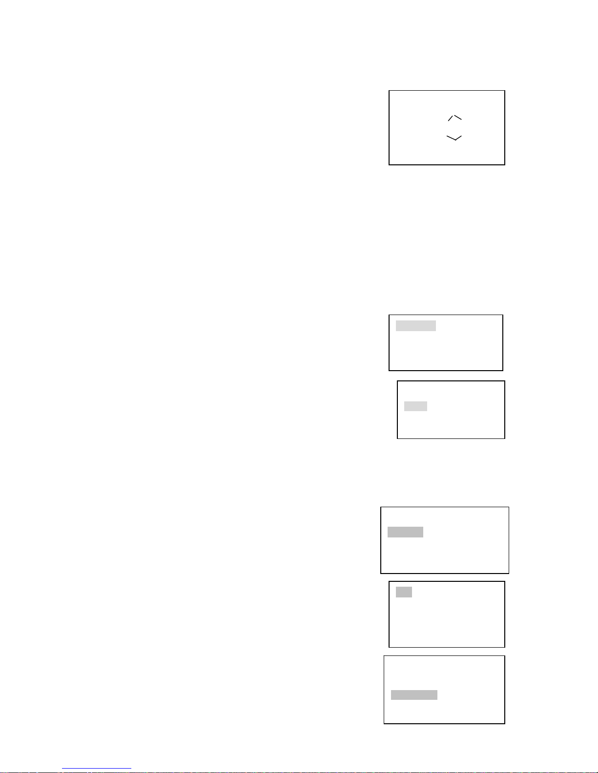
28
Scan Value :1
Scan setup >Left limit
Versatile scan Right limit
Random scan Speed
Scan Value :1
Scan setup > start
Versatile scan Stop
Random scan Speed
Speed:5
〈Zoom〉
〈Direction〉 〈Focus〉
〈Iris〉
Preset setup >value:1
GOTO
Remove
Scan Value :1
Scan setup > Begin
Versatile scan Stop
Random scan
• All the operations here are based on DH_SD protocol.
4.4.1 Direction Setup
4.4.1.1 Speed
It is to control direction. The value ranges from one to eight.
Please use the number buttons of the keyboard to input
value (between 0~8) and press ENTER to confirm.
(Operation here is only active with key-press. You can use
joystick to control directly. ) Note: for joystick use, the
speed is related to the joystick move range. If the farther the
joystick away from the center, the swifter the PTZ moves.
PTZ movement direction
• For joystick: up/down/left/right/up left/right down/up right/left down.
• For keyboard: up/down/left/right
4.4.1.2 Zoom/focus/Iris
• Zoom: please use WIDE and TELE to control PTZ zoom.
• Focus: please use FAR and NEAR to control PTZ focus.
• Iris: Please use CLOSE and OPEN to control PTZ aperture.
For joystick: clockwise to zoom out and anti-clockwise to zoom in.
4.4.2 Preset
4.4.2.1 Preset setup
After zoom and PTZ setup, input value and click ENTER to
confirm. Now you have set one preset.
4.4.2.2 GOTO
Move cursor to highlight GOTO.
Input preset value and click ENTER.
System goes to specified preset.
4.4.2.3 REMOVE
Move cursor to highlight REMOVE. Input preset value and click ENTER.
Now you have removed one preset.
Note: Some protocols do not support remove preset function. You can modify
to replace the previous one.
4.4.3 Scan
4.4.3.1 Scan setup
、Input value and then move cursor to highlight left limit.
Or you can use joystick to move camera to left limit and
then click ENTER.
、Repeat procedure one to set right limit.
、Move cursor to highlight speed. Input speed value and
click ENTER to confirm.
4.4.3.2 Scan operation
、Use up/down to highlight scan. Input scan
value and click ENTER to begin scanning.
、Use left/right keys to highlight stop. Click ENTER to
stop scanning.
Preset setup >Value:1
GOTO
Remove
Page 33
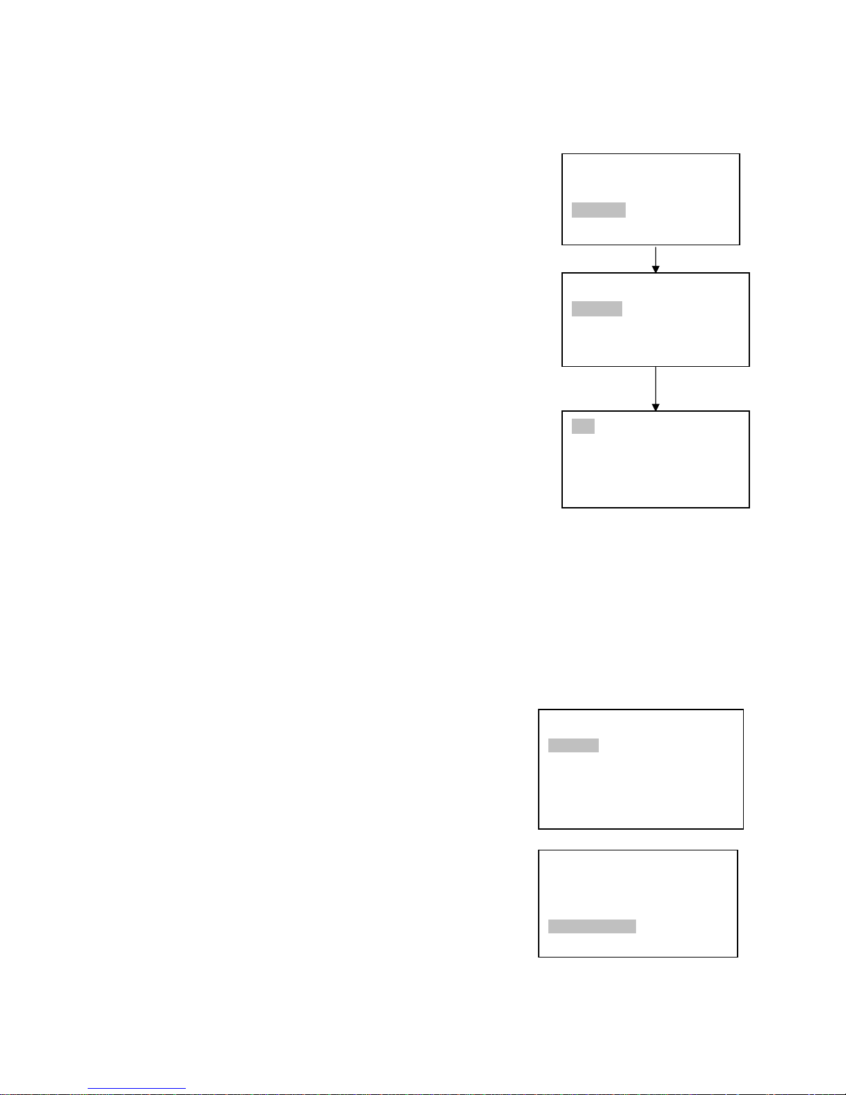
29
Note: for versatile scan and random scan, you need
Corresponding protocols to support.
4.4.4 Tour
4.4.4.1 Tour setup
Use up/down keys to highlight add to tour. Input value in tour
group.
For example, here we want to add tour point 2 and 3 in tour
group 1.
• Firstly, input 1 in tour group.
• Secondly, input 2 to tour and then click ENTER. Now you
have added tour point 2 to tour group 1.
• Thirdly, input 3 to tour and then click ENTER. Now you
have added tour point 3 to tour group 1.
You can repeat the above procedures to add more tour point.
4.4.4.2 Tour operation
• Speed
Please use up/down keys to highlight tour setup.
When cursor is before speed, you can input speed value.
• Duration
Use left/right keys to highlight duration and then you can input
duration value.
• Begin touring
Use up/down to highlight tour and then input value. Now you can click
ENTER to begin tour.
• Stop touring
Move cursor to highlight stop and then click ENTER. Now you have
stopped touring
4.4.4.3 Remove
4.4.4.3.1 Remove tour
Move cursor to highlight remove tour and then input corresponding value. Click
ENTER to delete current tour.
4.4.4.3.2 Remove tour point
• Move cursor to highlight tour group and then input
corresponding value.
• Please click Enter to confirm all the operation below is
active to current tour group.
• Move cursor to highlight tour point and input
corresponding value (such as 2).
• Now click ENTER to delete.
For example, you want to remove tour point 5 and 6 in tour
group 2.
• Firstly, input 2 in tour group and click ENTER.
• Secondly, input 5 in tour point and click ENTER. Now
you have deleted tour point 5
• Thirdly, input 6 in tour point and click ENTER. You have
deleted tour point 6.
Tour
Tour setup > Tour group:1
Add to tour Tour:
Remove tour
Tour Value :1
Tour setup > Start
Add to tour Stop
Remove tour
Tour Value :1
Tour setup > Speed
Add to tour Duration
Remove tour Remove tour group
Tour
Tour setup > tour group:1
Add to tour point Tour point:
Remove tour point
Tour Value :1
Tour setup Speed
Add to tour duration
Remove tour > Remove tour group
Page 34
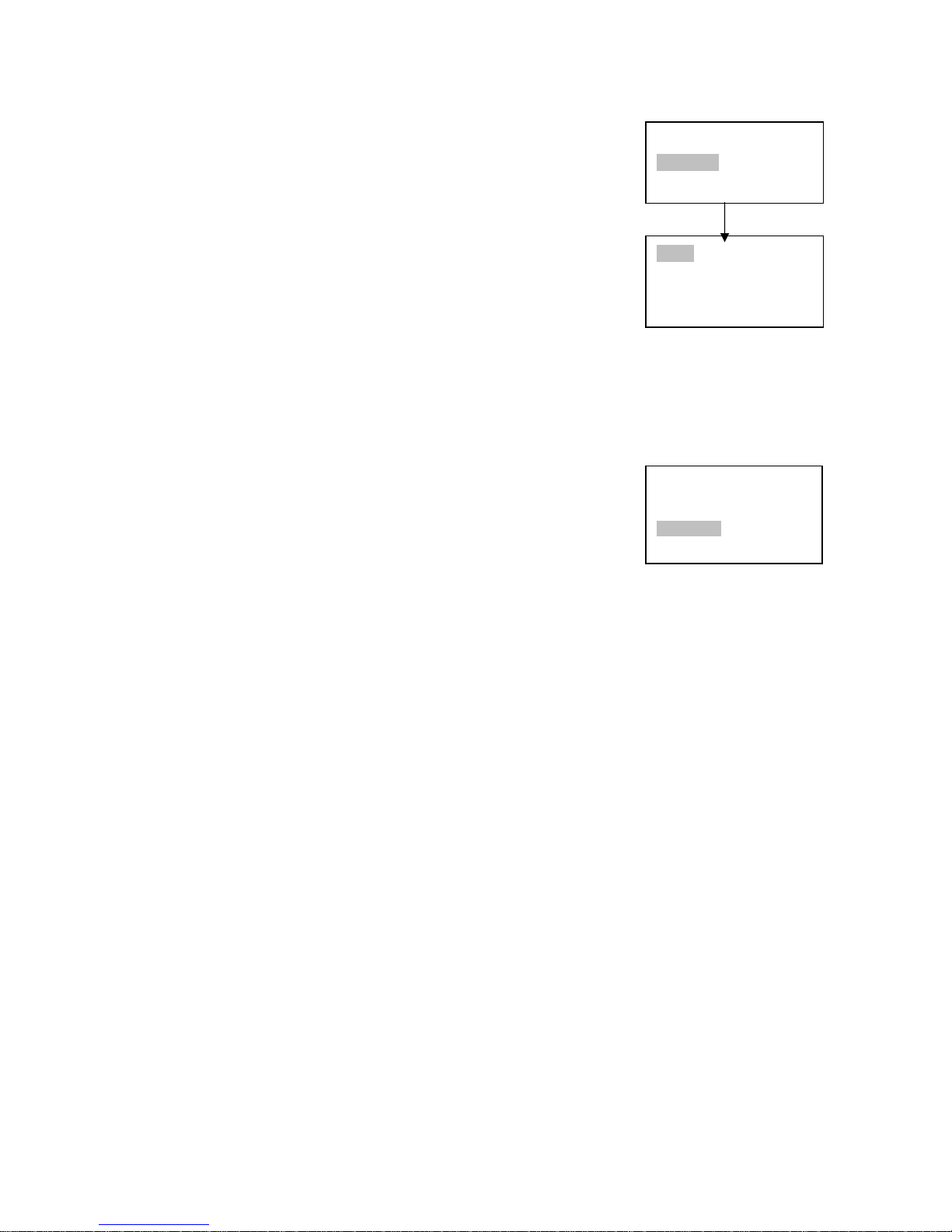
30
Pattern Value:1
Patter setup > Start
Rotation Stop
Pattern Value:1
Pattern setup Start
Pan rotation Stop
>S
peed
4.4.5 PATTERN
4.4.5.1 Pattern setup
• Move cursor to highlight pattern and then input pattern
value. Input value is the pattern path you want to set
(Maximally support five paths). Click ENTER to confirm.
• Move cursor to highlight start and then input pattern value.
Now click ENTER to confirm.
• Move cursor to highlight stop. Input pattern value and click
ENTER to stop pattern. Dome will automatically memorize
all the operations you have done.
4.4.5.2 Pattern operation
• Pleas use up/down keys to highlight pattern. When cursor is
before start, please input pattern value and then click ENTER
to begin pattering.
• Move cursor to highlight stop and then click ENTER. System
stop pattern.
4.4.6 Pan Rotation
Move cursor to highlight speed. Input speed value (the speed
you want) and click ENTER.
Then move cursor to highlight start and then click ENTER.
Dome begins pan rotation.
Move cursor to highlight stop and then click ENTER. Dome stops
rotation.
Pattern Value:1
Pattern setup >Start
Rotation Stop
Page 35
31
5 Web client operation
5.1 Network connection
Before web client operation, please check the following items:
z Network speed dome network connection is right
z DVR and PC network setup is right. Please refer to general-system setting-
network setup
z Use order ping ***.***.***.***(* network dome IP address) to check connection is
OK or not. Usually the return TTL value should be less than 255.
5.2 Login and logout
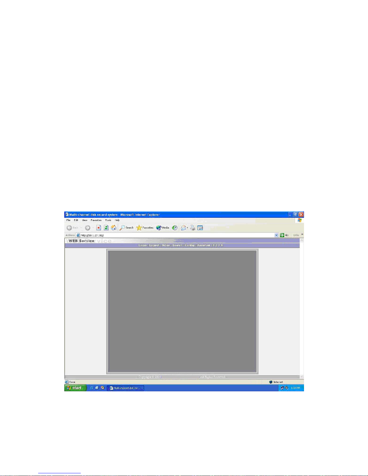
Open IE and input network speed dome address in the address column.
For example, if your dome IP is 10.1.27.200, then please input http:// 10.1.27.200 in
IE address column.
System pops up warning information to ask you whether install controls or not.
Please click “Yes” continue.
After installation, the image shows is shown as below. See figure 5-1.
Note: Default factory IP is 192.168.1.108 and default subnet mask is 255.255.255.0.
5-1
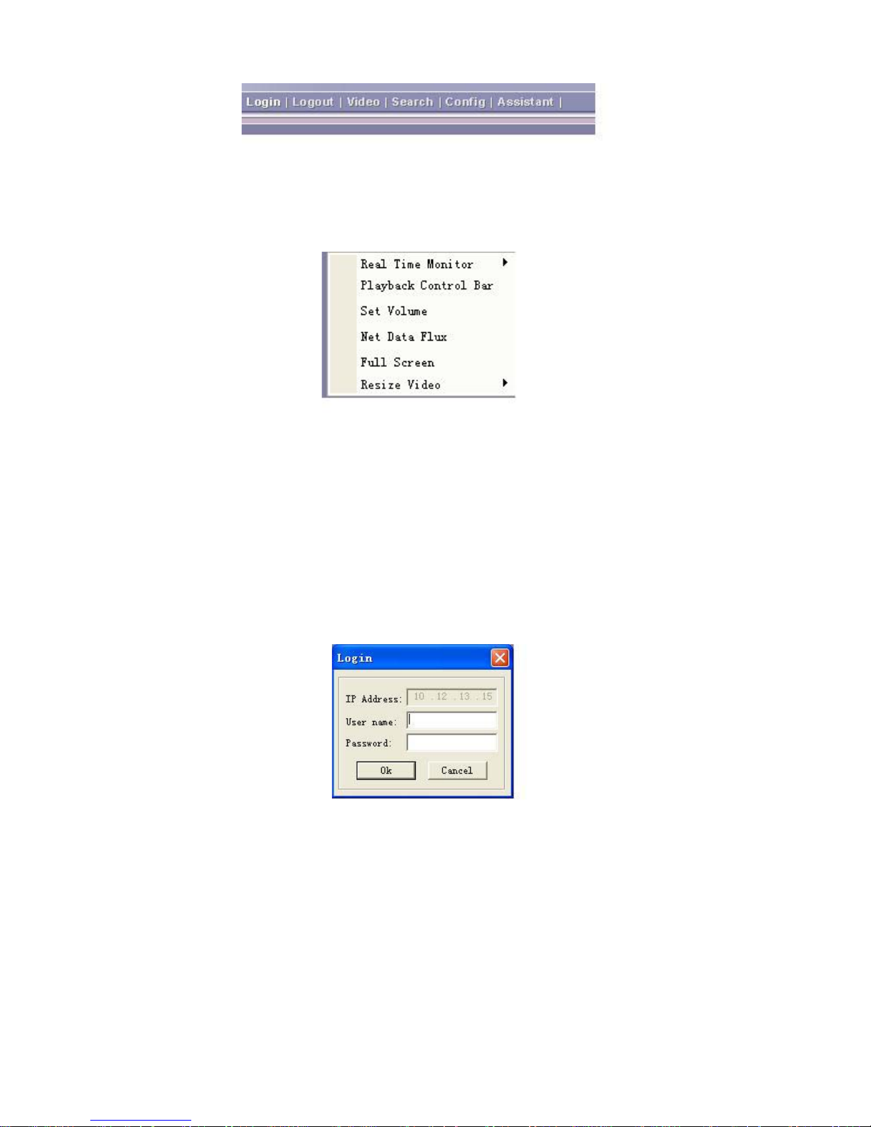
There are six function keys: login, logout, video, search, configuration and assistant.
See figure 5-2.
Page 36
32
5-2
5.2.1 Before login
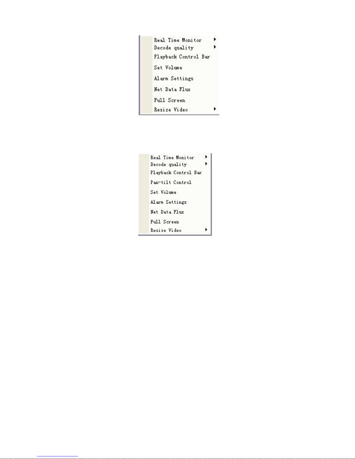
Before login, right click mouse, you can see an image is shown as in figure 5-3.
5-3
5.2.2 After login
Click login the following image will pop up. See figure 5-4.Please input your user name and
password.
Note:
z Default account is: user name: admin: password: admin. That account is a
reserved account which you can not delete. You can only modify its password.
z For security reasons, please modify your password after you first login.
z System automatically locks current account for thirty minutes after five times
password failure.
5-4
5.3 Video (Right mouse menu operation)
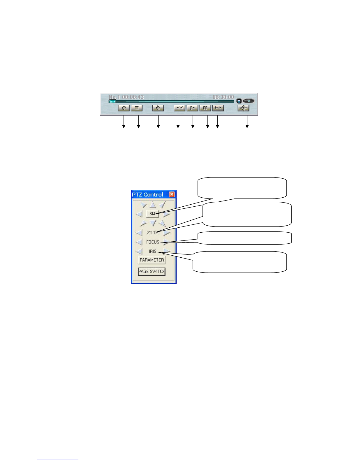
After login, click video button or right click mouse, the image is shown as below. See
figure 5-5.
Page 37
33
5-5
When you are in surveillance mode, right click mouse the image is shown as in
figure 5-6. You can see there added a new item: Pan-tilt control.
5-6
z Real time surveillance: choose the channel you want to implement real time
monitor.
z Decode quality: there are totally four levels: general, good, better and best.
z Playback control bar: for you to control playback.
z Pan-tilt control: before operate, please make sure you have selected right pan-
title protocol for DVR
z Set volume: Here is for you to adjust audio.
z Alarm settings: Here is for you to set alarm.
z Net data flux: Here is for you to review current net data.
z Full screen: click this button to review in full screen mode.
z Resize video: there are several ratios: 33%, 66% and 100%.
5.3.1 Real-time surveillance
Here is for you to select the channel you wan to implement real-time monitor.
5.3.2 Decode quality
Here is for you to select decode quality. There are totally four levels: general, good,
better and best.
5.3.3 Playback control bar
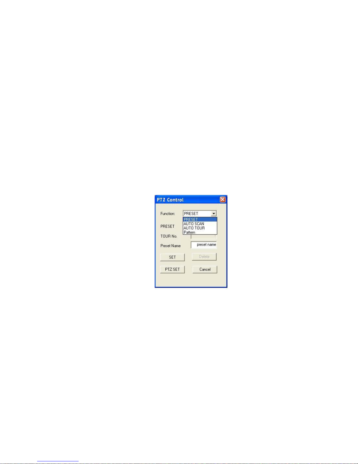
Here is the playback bar when you are viewing video file. See figure 5-7.
1: Save record
Page 38
34
2: Stop
3: Snapshot
4: Slow replay
5: Play
6: Pause
7: Fast play
8: Full screen
1 2 3 4 5 6 7 8
5-7
5.3.4 PTZ Control
In figure 5-6, select pan-tilt control, the image is shown as in figure 5-8.
5-8
Note:
If you see some items such as preset protocol or speed protocol in grey color which
you can not set, please apply your local network administrator for proper rights.
In this dialogue interface (figure 5-8), you can implement the following functions.
(1) Pan and tilt movement
You can use the eight direction key around SIT to control PTZ pan and tilt movement.
The speed you can set in parameter setup.
(2)Proportional pan and tilt
This function keeps the image from moving too fast when there is a large amount of
zoom.
Dome continually decrease or increase pan and tilt speeds in proportion to depth of
zoom. When zooms speed is increasing, the camera moving speed becomes slow.
When zooms speed is decreasing, the camera moving speed becomes fast.
SIT is 3D positioning button. Around
SIT are eight PTZ directions keys.
Left key: zoom out. Right key: zoom
in.
Left key: zoom in. Right key: zoom out
Left key: turn dark. Right key: turn
bright.
Page 39
35
(3)Auto flip
As long as you continue to hold the joystick in the down position, the dome rotates
180 degrees and repositions itself for uninterrupted viewing of any subjects that
passes directly beneath the dome.
(4)3D auto location
Working with DVR, click SIT button and then click one point in scene, current screen
will be displayed in the central window. Drag mouse move down is to zoom in; drag
mouse move up is to zoom out. The smaller the zone size, the bigger the zoom
amount. All of these allow you to trace fast.
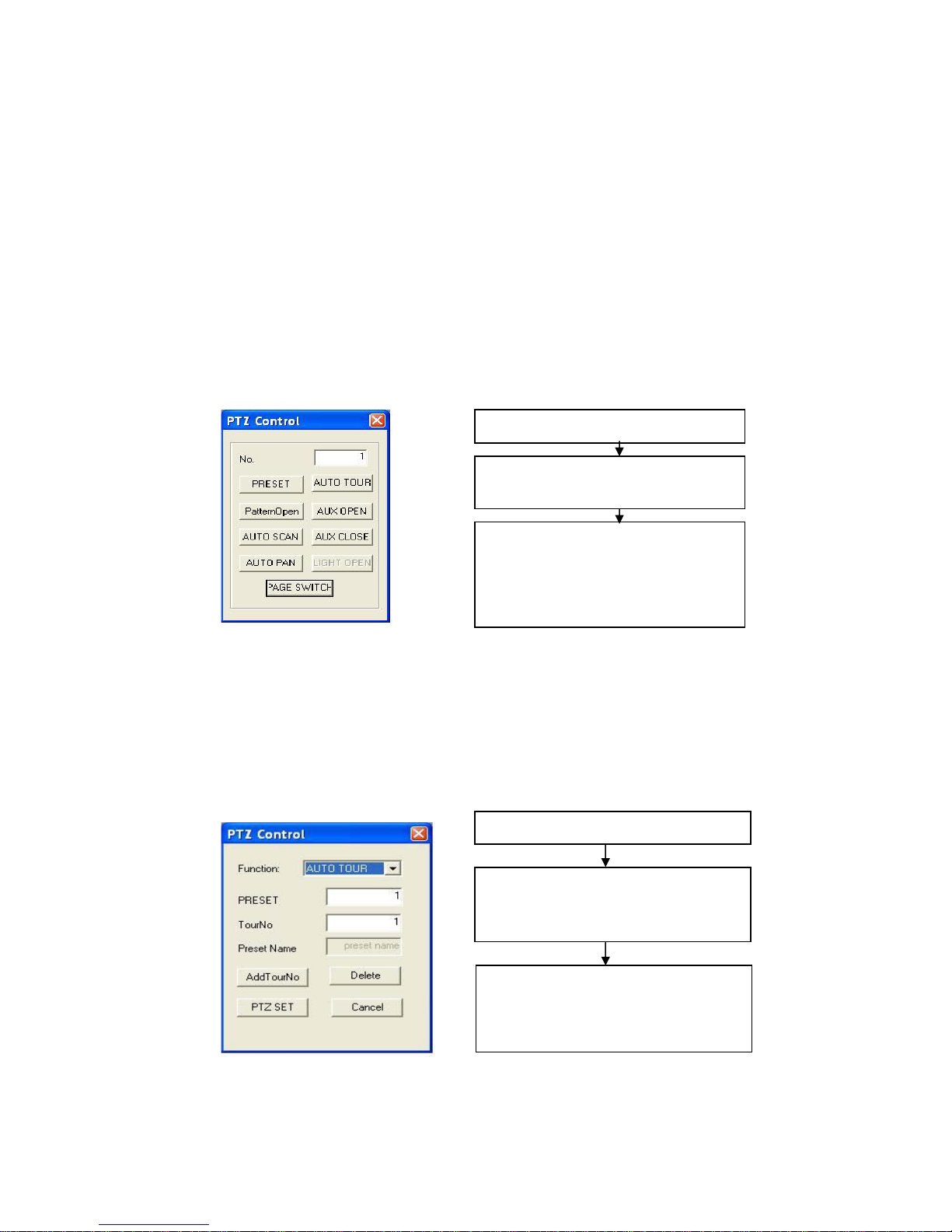
(5) Parameter setup
Click parameter setup button in figure 5-8. The image is shown as below. See figure
5-9.
Here you can select the following four items:
z Preset
z Auto scan
z Auto tour
z Pattern.
5-9
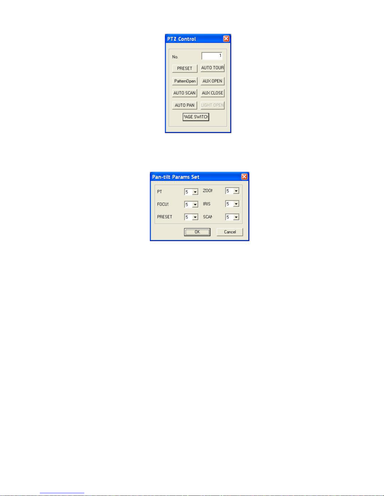
(6) Page change
In figure 5-8 click page change button, the image is shown as below. See figure 5-
10.
No. column here is for you to input corresponding values.
Click page change again, system goes back to figure 5-8.
Page 40
36
5-10
(7) Speed setup
Network speed dome is to control direction operation. There are eight levels ranging
from 1 to 8. Level 8 is the fastest speed. See figure 5-11.
5-11
5.4 Camera setting
Here is for you to control network speed dome camera.
5.4.1 Zoom
In figure 5-8, click buttons beside zoom to adjust focus. Left button is to zoom out
and the right button is to zoom in.
5.4.2 Focus
Focus is a process to adjust the object or scene definition. Click right button beside
the focus, the object faraway becomes clear. Click left button beside the focus,
object near you becomes clear. You can use these two buttons to get a vivid scene.
Please note focus is in auto mode after initialization, dome pan or tilt movement or
zoom in, zoom out.
In the following environment, camera can not auto focus the object.
z Object is not in the centre
z Camera can not review clear objects faraway and near at the same time.
z Object is of strong light such as neon light or spotlight.
z Fast moving object
z Wide area, flat objects such as wall.
z Object is too dark or blur.
Page 41
37
5.4.3 Iris
Iris is to adjust camera image brightness. Click right button near iris screen becomes
brighter while click left button near iris the screen becomes darker. You can use
these two buttons to get ideal
Iris is in auto mode after initialization, dome pan or tilt movement or zoom in, zoom
out.
In auto mode, camera can automatically responds to the light change to output
stable and vivid image.
5.4.4 Preset
Preset is to memorize current dome pan, tilt, focus and etc for future use.
This series network speed dome support 80 presets.
Note:
Preset name can be modified.
System supports multiple languages such as simplified Chinese, English.
5-12
5.5 Auto tour
Auto tour is a build-in function of this series dome.
You can add presets into a tour in a desired order and then set dwell time for each
preset. The dome will begin an auto touring between these presets.
Each tour can maximum consists of 80 presets.
5-13
Select tour number.
Input preset number and then click “add
tour no “button to add current preset into
In figure 5-12, input tour number in No.
column. Click auto tour button. System
begins touring.
Move PTZ to your desire start location.
In figure 5-9, click set button. Then you
can
g
o on settingother
p
resets.
In figure 5-8, click page change button,
system goes to figure 5-12. Input preset
number and click preset button, you can
call up preset now.
Page 42
38
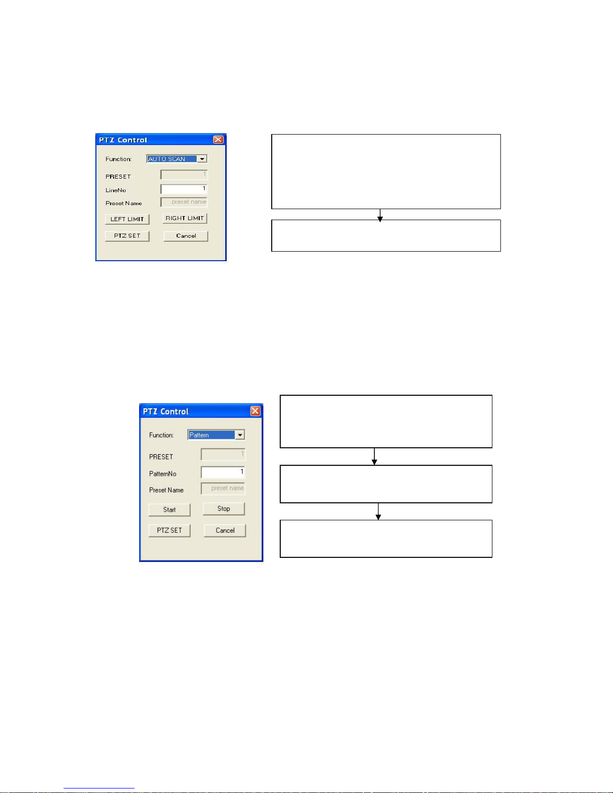
5.6 Auto scan
Auto scan function allows camera to scan back and forth regularly in a horizontal
field. Here you need to set left and right limit and scan speed. System support five
scan route.
5-14
5.7 Auto pattern
This series network speed dome can memorize user PTZ manual operation, focus
zoom in/out, speed and etc. The dome begins moving from the start point to the end
point as pre-specified. One operation can last for maximum two minutes. Focus and
iris are in auto mode during auto pattern process.
5-15
Move PTZ to your start location and then click “left
limit” button in figure 5-14.
Move PTZ to your stop location and then click “right
limit” button in figure 5-14.
Now you have finished one scan setup.
In figure 5-12, click auto scan button, system begins
auto scan process.
Select mode in PTZ movement options.
Click start button in figure 5-15, you can move
PTZ and implement camera operations.
After all the operations, click stop button in
figure 5-15. Now you have set one pattern.
In figure 5-12, click auto pattern button, system
begins auto pattern process.
Page 43
39
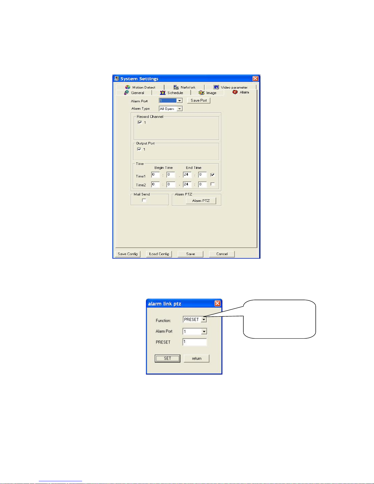
5.8 PTZ Alarm input and output setup
In the main window, click configuration button and then click alarm button. You can
see the image is shown as below. See figure 5-16.
5-16
In figure 5-16, click Alarm PTZ button. You can see PTZ alarm setup interface. See
figure 5-17.System supports two alarm input ports.
5-17
There are three options:
preset, auto scan and
auto tour.
Page 44
40
5.9 Call assistant function
You can refer the following sheet for assistant function.
Assistant
button NO.
Open Close Assistant
button
NO.
Open Close
23 Open
backlight
compensation
Close
backlight
compensation
24 Open
digital
zoom
Close
digital zoom
27 Close
Day/Night
mode
Open
Day/Night
mode
35 Increase
shutter time
Decrease
shutter time
41 Increase
brightness
Decrease
brightness
42 Open auto
flip function
Close auto
flip function
43 Display
preset name
Hide preset
name
80 Restore to
factory
default
setting
Page 45
41
6 Other Functions in Web Menu (Configuration/Assistant)
6.1 Configuration
In web menu, click configuration button the image is shown as in figure 6-1. There
are totally seven function keys.
6-1
6.1.1 Load and save configuration
6.1.1.1 Save configuration
Click save configuration button in figure 6-1.You can save current configuration to a
file. The file extension name is CFG. See figure 6-2.
6-2
Page 46
42
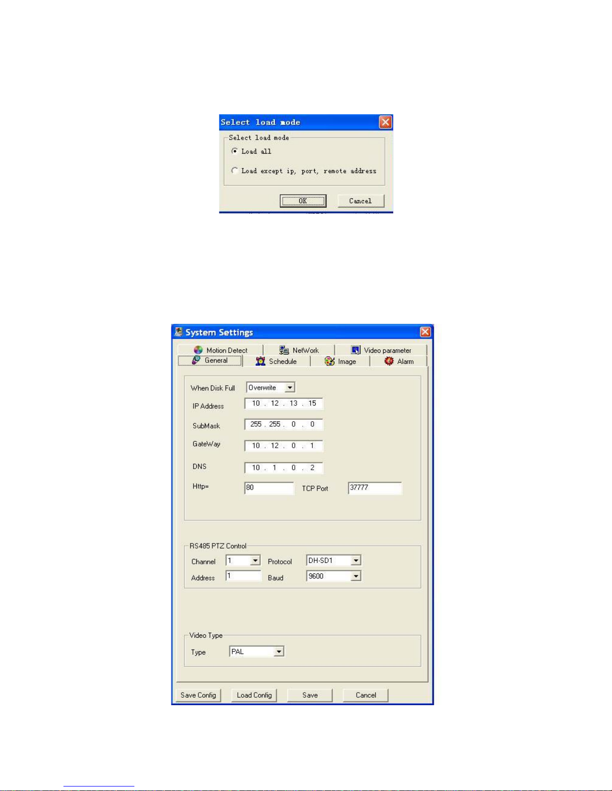
6.1.1.2 Load configuration
You can click load configuration button in figure 6-1 to load you previously backup
file. See figure 6-3.Click Ok button and then select file of extension name .CFG. Now
you have updated system setup.
6-3
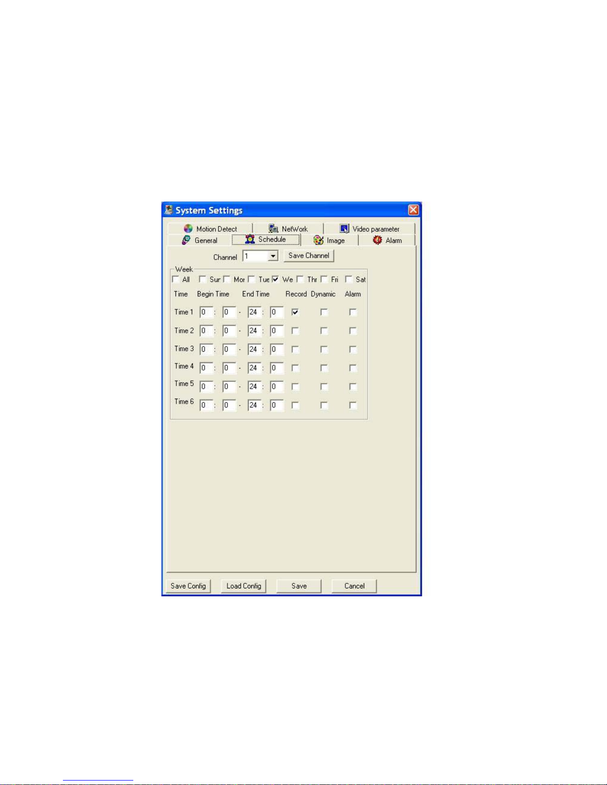
6.1.2 General
In figure 6-1, click general button. You can see an image is shown as in figure 6-4.
Here is for you to input network information and select corresponding protocol.
Note:
Improper network setup will trigger error dialogue box!
System will reboot and prompt you to login again after successful IP modification!
6-4
Page 47
43
6.1.3 Scheduled
Click scheduled, the image is shown as below. See figure 6-5.
Here is for you to set record information.
There are three record modes: record, dynamic and alarm. You can draw a √ in
the corresponding check box.,
Please click save button after all the setup.
Note:
z All the video files here are saved in server; you need to install central
management software first.
z The start time should earlier than the end time.
6-5
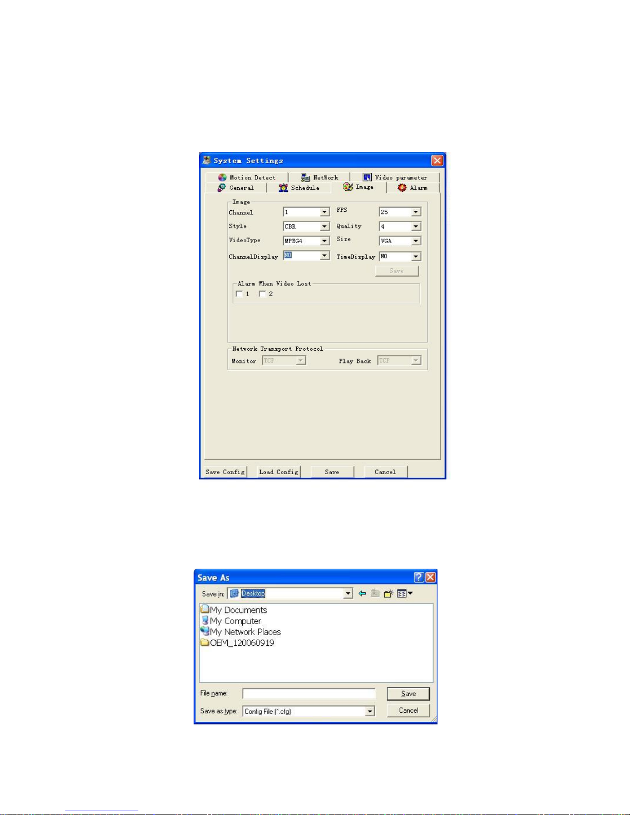
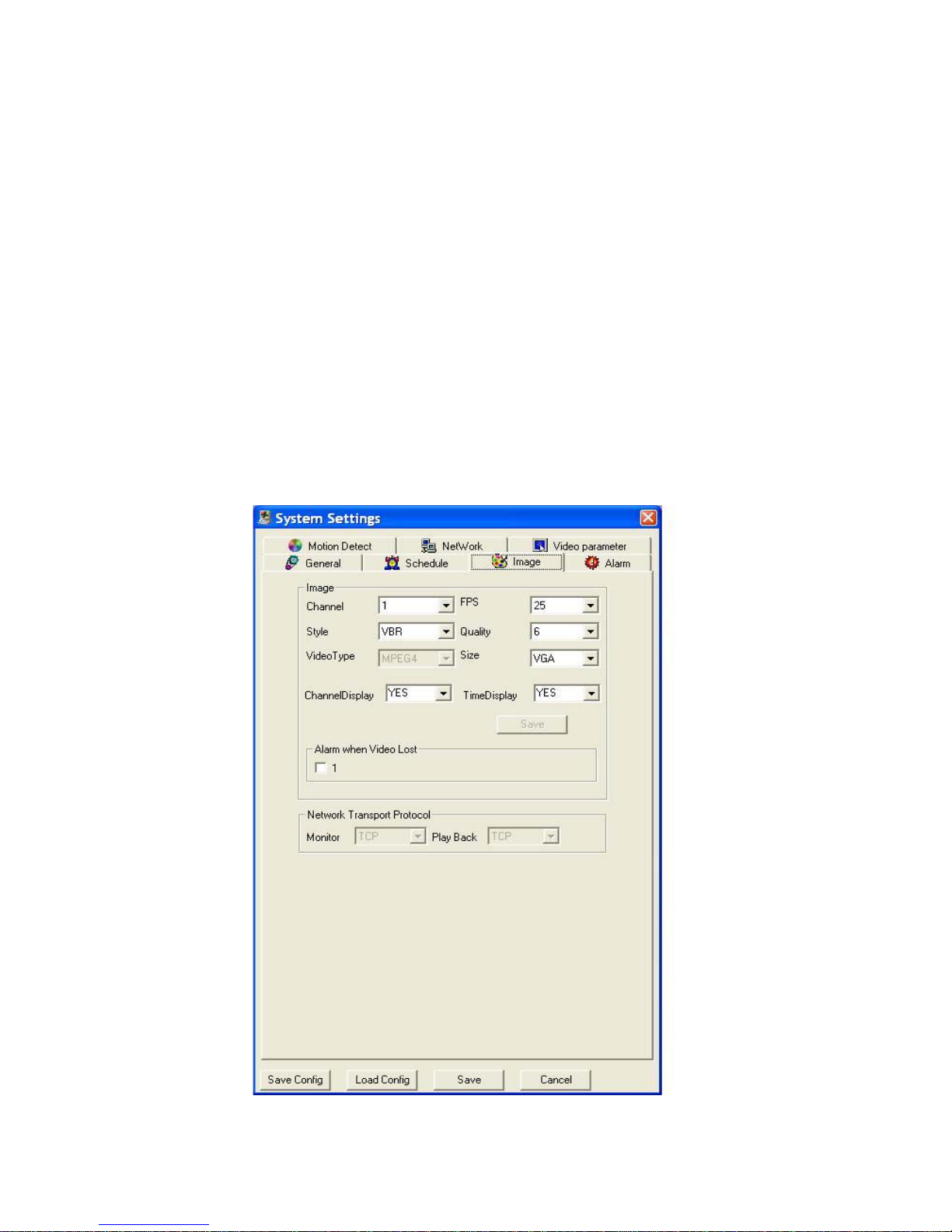
6.1.4 Image
In figure 6-1 click image button, the following dialogue box pops up. See figure 6-6.
Here you can set image information and view network protocol.
Click <save> below “time display” to save a configuration for one channel.
After all the setup please click <save> in the bottom to save all settings.
• FPS:PAL:1/2/3/6/12/25;NTSC: 1/2/4/7/15/30.
• Video Type:Only MPEG4 is available.
Page 48
44
• Quality: There are six levels ranging from 1to 6. 6-level is the best image
quality, but the largest data flux.
• Resolution:HD1/CIF/QCIF/VGA / QVGA.
• Style:
¾ CBR: constant bit rate, bit rate is based on other parameters setting,
for example FPS, image quality, size etc. See details in appendix, on
the last page.
¾ VBR: variable bit rate, no more than 1M.
• Alarm when video lost:Here you can set system alerts you or not when video
loss occurred. Please draw a √ before channel number to activate this
function.
• Network Transport Protocol: Here you can review protocol of monitor and play
back.
Note:
• VBR is recommended for monitoring
• Appendix is for your information only. The bit rate may be different because of
different network or different video.
6-6
Page 49
45
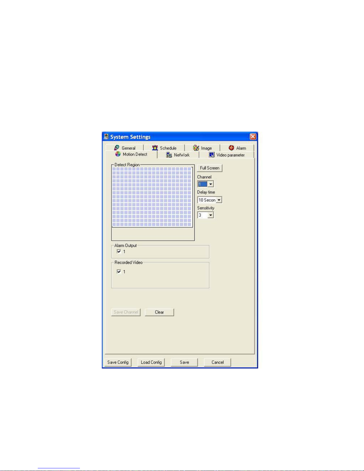
6.1.5 Motion Detection
Click motion detention button, the image is shown as in figure 6-7.
This function gets activated except scheduled time period.
You can click you mouse in the detection region to set motion detection area. The
blue area is the motion detection zone.
• Channel: here is for you to select channel number.
• Delay time: system delays specified time you have set after alarm is cancelled.
• Sensitivity: here you can set area sensitivity.
• State: there are two modes: on/off.
Note:
This function is nor available in current version.
6-7
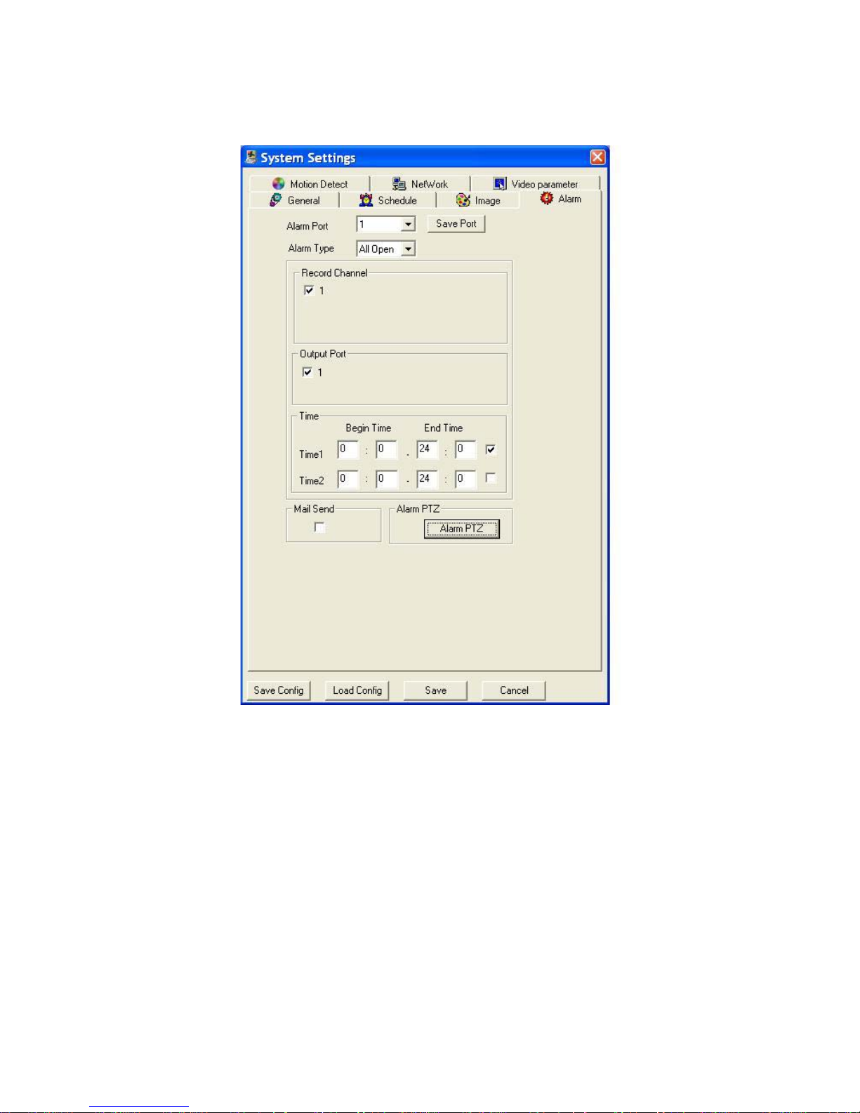
6.1.6 Alarm
Click alarm button you can see an image is shown as in figure 6-8.
• Record channel:You can draw a √ in the check box to activate this function.
• Record Channel:You can draw a √ in the check box to activate this function.
• Time:You can set two periods here.
• Mail Send:You can draw a √ in the check box to activate this function.
Page 50
46
When you finish all the setup here please clicks “save” in the bottom to save all
configurations.
6-8
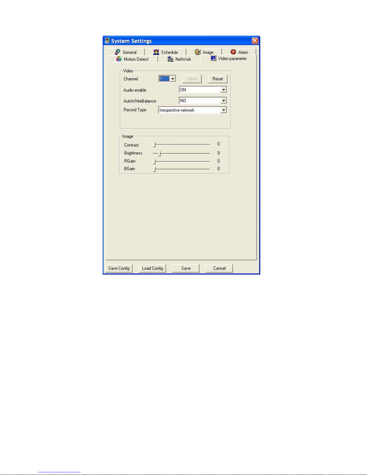
6.1.7 Video setup
Here is for you to select hue, contrast, brightness and saturation for each channel (or
all channels). You can also open or close audio. See figure 6-9.
Page 51
47
6-9
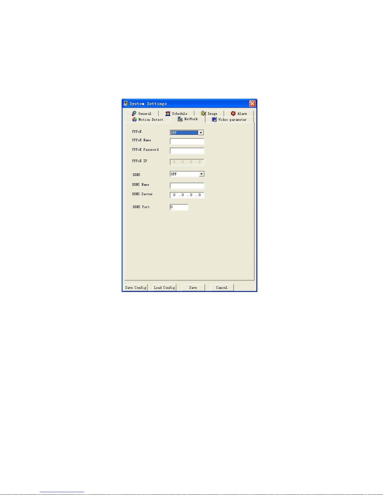
6.1.8 Network Setup
Click network button, the image is shown as in figure 6-10.
6.1.8.1 PPPoE Connection
Set PPPOE as on, and then please input “PPPoE name” and “PPPoE password” you
get from your ISP (Internet service provider).
After saving it, you need to restart to active your configuration.
After rebooting, network speed dome will connect to internet automatically. The IP in
the PPPoE IP is the dynamic value.
6.1.8.2 Web visit via PPPoE
There are two ways.
a. visit through current IP
After network speed dome connect with Internet by PPPoE, please go to figure 6-10
to get your device’s current IP in “ PPPoE IP” . Now you can visit this network speed
dome via this IP.
b. Visit via DNS
You need a PC of fixed IP in the internet and there is the DDNS software running in
this PC. In other words, this PC is a DNS (domain name server).
Page 52
48
In network DDNS, input your PPPoE name you get from you IPS and server IP (PC
with DDNS). Click save and then reboot system.
Click save button, system prompts for rebooting to get all setup activated.
After rebooting, open IE and input as below:
http://(DDNS server IP)/(virtual directory name)/webtest.htm
e.g.: http://10.6.2.85/network speed dome_DDNS/webtest.htm.)
Now you can open DDNS Server web search page.
6-10
6.2 Assistant
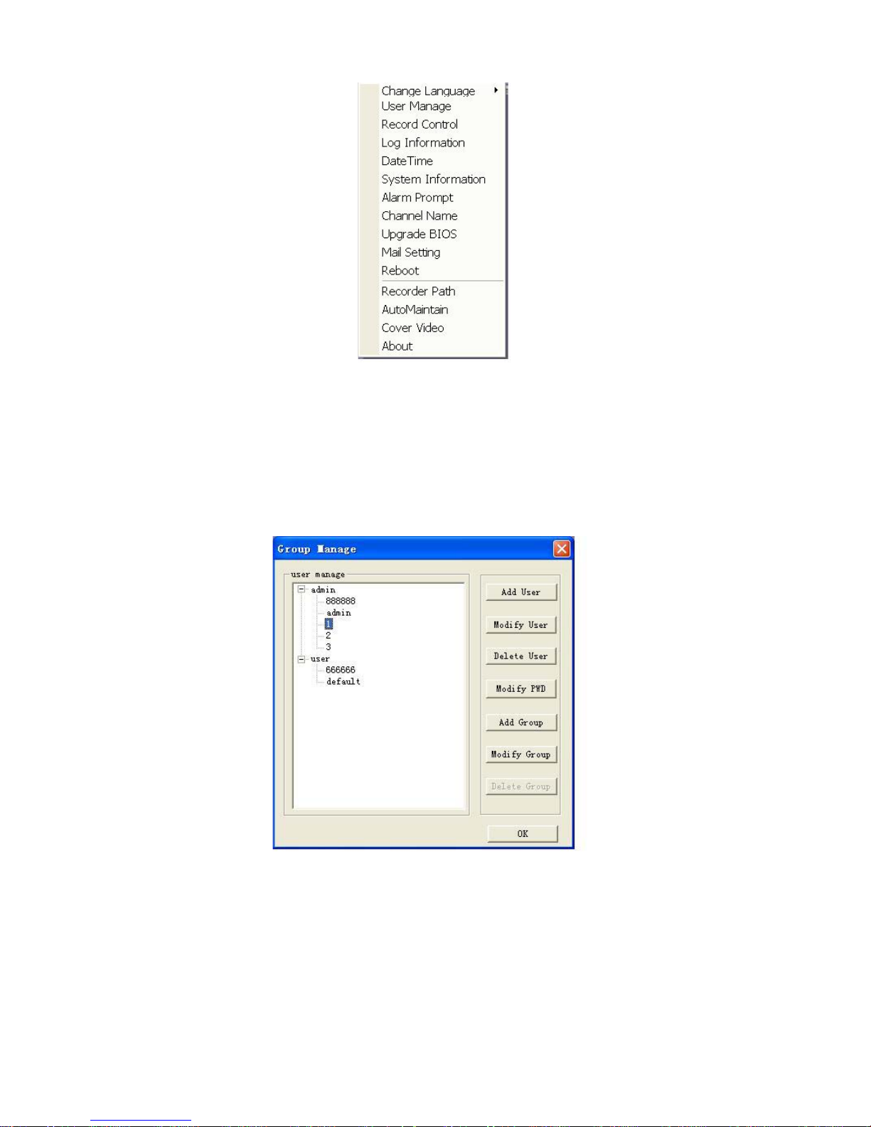
6.2.1 Main menu
Click assistant button, the image is shown as in figure 6-11.
Page 53
49
6-11
6.2.2 Change language
System can switch between simplified Chinese and English. System needs to reboot
before modification becomes activated.
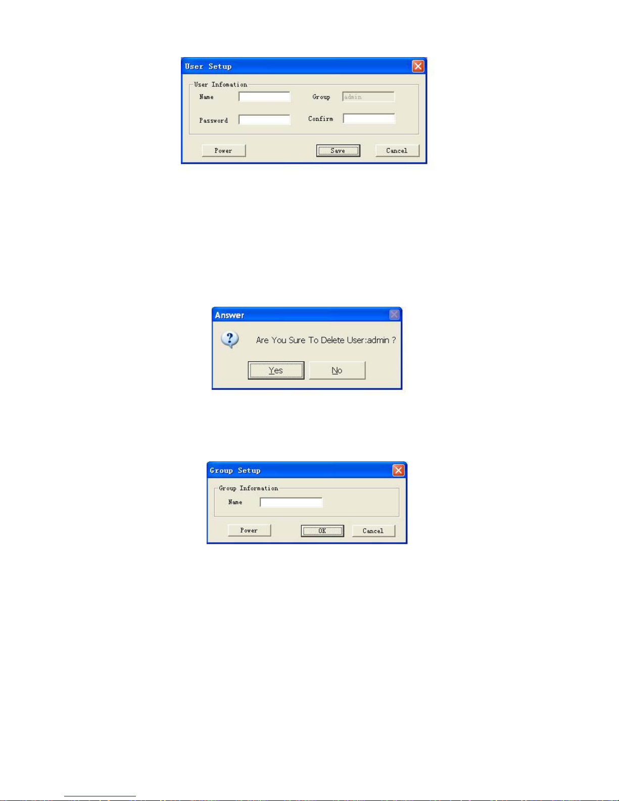
6.2.3 User manage
Click user manage button, the image is shown as below. See figure 6-12.
6-12
6.2.3.1 Add user
Click add user button, the image is shown as below. See figure 6-13.
You can input corresponding new user information in current dialogue box.
Please note one user must belong to one group and its right shall not exceed the
group rights.
Page 54
50
6-13
6.2.3.2 Modify user
Modify user dialogue box is similar to Figure 6-13. You can modify user information
and then click save button to return.
6.2.3.3 Delete user
Click delete user button, system pops up the following dialogue box asking you to
confirm. Click Yes to delete. See figure 6-14.
Please note only administrator can delete user. The user to be deleted should be offline.
6-14
6.2.3.4 Add group
Click add group button, the following dialogue box pops up for you to input new
group name. See figure 6-15.
6-15
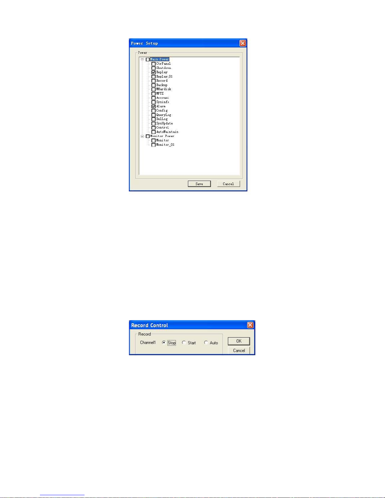
Click power button, the image is shown as in 6-16.
Here you can select corresponding right for the new added group. Please draw a √
before the check box.
Page 55
51
6-16
6.2.3.5 Delete group
Click delete group button, system pops up dialogue box asking you to confirm.
Click Ok to delete selected group.
Note: you can only delete empty group (no user in the current group)
6.2.3.6 Modify group
Click modify group, system pops up the dialogue box for you to modify rights setup.
Please note when you delete one right for whole group, you need to make sure no
user in current group has that right!
6.2.4 Record control
Here you can manually control channel recording status such as stop recording, auto
record or manual record. Please draw a √ before the check box. See figure 6-17.
6-17
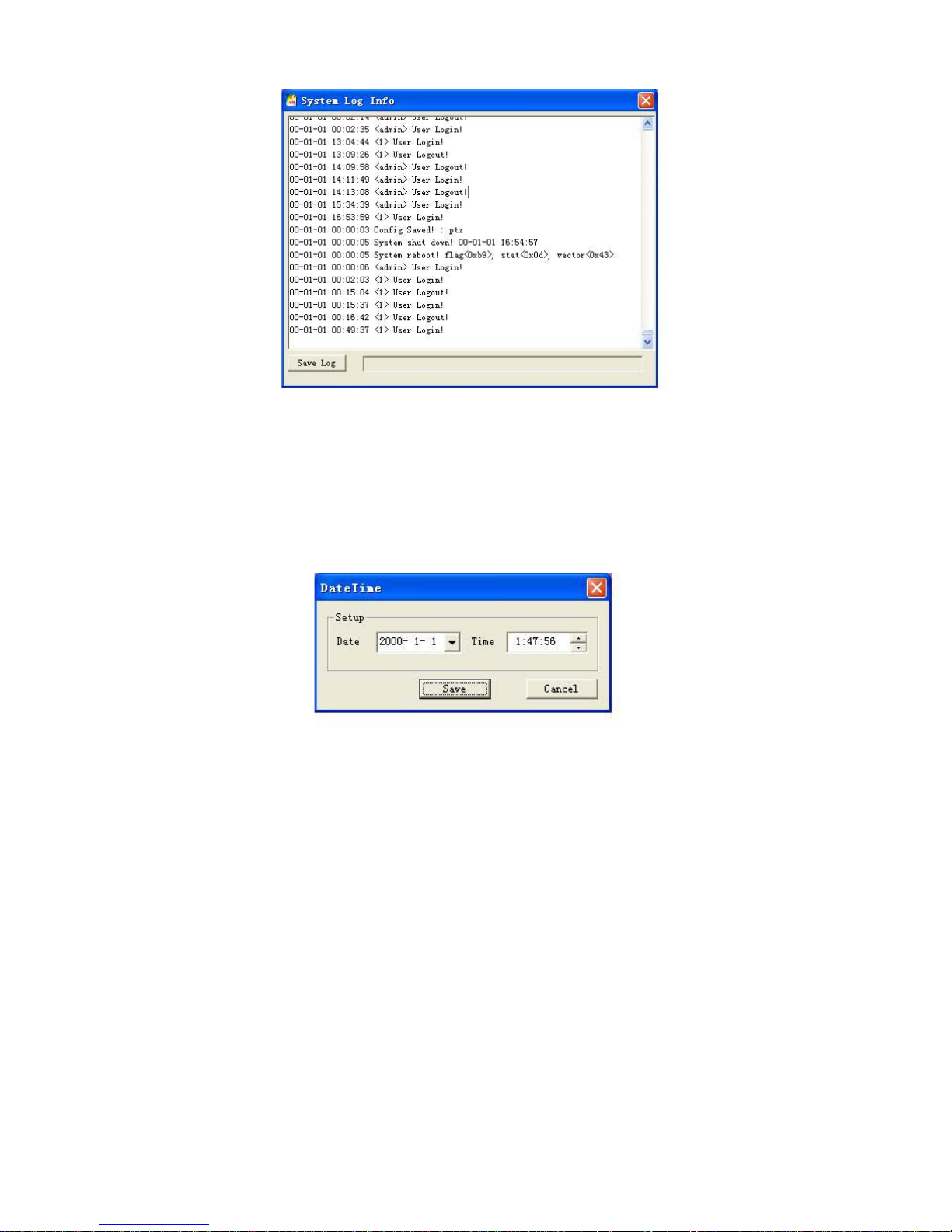
6.2.5 Log Information
Here is for you to view log files. See Figure 6-18.
All the log files here are for users or service engineer to review.
Do not delete casually.
Page 56
52
6-18
6.2.6 Date Time
Here is for you to modify equipment time and date. See figure 6-19.
Note:
You need proper right to modify these items since time is very important factor in
system.
6-19
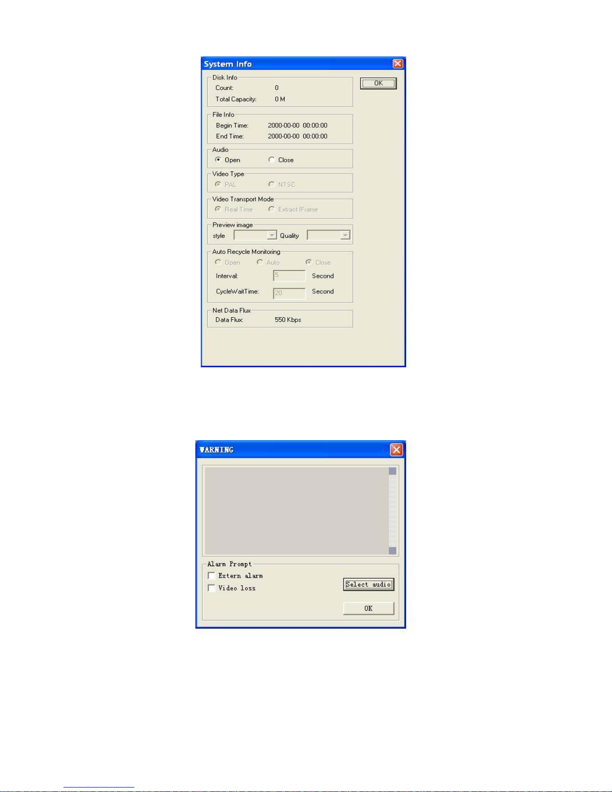
6.2.7 System Information
Here you can view current network speed dome running status. See figure 6-20.
Page 57
53
6-20
6.2.8 Alarm prompt
Here you can select audio file and type. You can draw a √ before the check box.
See figure 6-21.
6-21
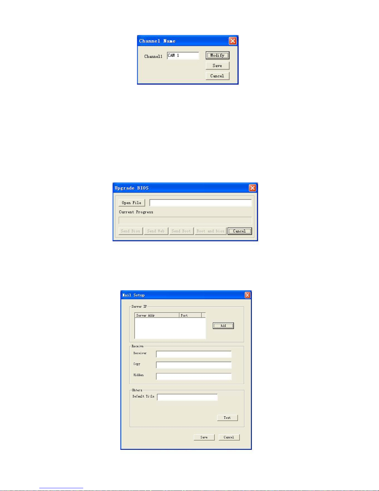
6.2.9 Channel name
Here is for you to modify channel name.
System only supports maximally 8 Chinese characters or 16 English
characters/numerals.
Page 58
54
6-22
6.2.10 Upgrade BIOS
Before upgrading, you can get upgrade file from our local engineer or download from
our website.
During upgrade process, power failure will terminate the whole upgrade process!
In figure 6-23 click open file, select the directory and click send data button, system
automatically begin upgrading BIOS.
Note:
After successful upgrade, system needs to reboot to get all setup activated.
6-23
6.2.11 Mail Setting
This interface is for you to input mail settings. See figure 6-24.
Page 59
55
6-24
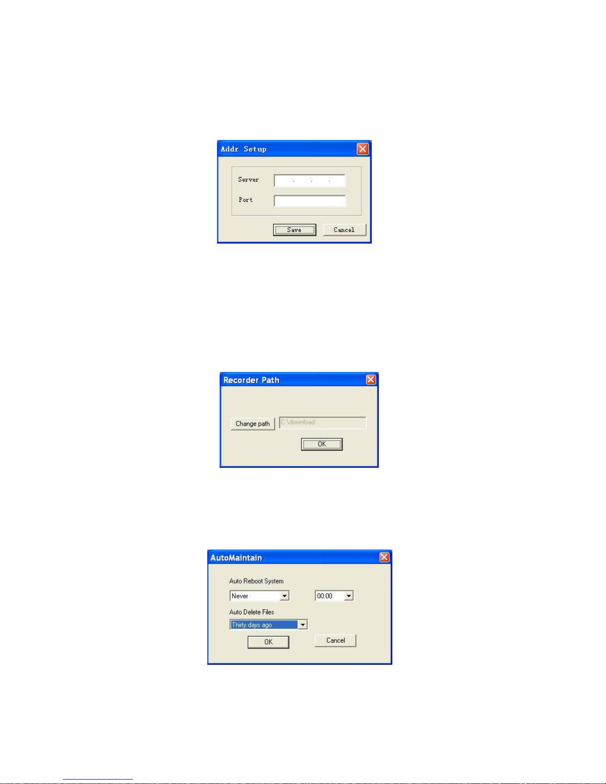
6.2.11.1 Email server IP address
In figure 6-24, select server IP and then click add button. System pops up the
following dialogue box. See figure 6-25.You can input server network information
here.
6-25
6.2.11.2 Receiver email address
You can set one to three email addresses. System can send the email to you
specified addresses. You can input title in others column.
After setting, click test button, you can check all the settings here are right or not.
6.2.12 Record directory
Here is for you to specify the directory where you can backup recorded video files.
See figure 6-26.
6-26
6.2.13 Auto Maintenance
Here is for you to set auto reboot time.
You can select time to auto reboot system and the time to auto delete file time.
Please select from the drawdown list. See figure 6-27.
6-27
6.2.14 Privacy Mask Zone
Here is for you to set privacy mask zone.
Page 60
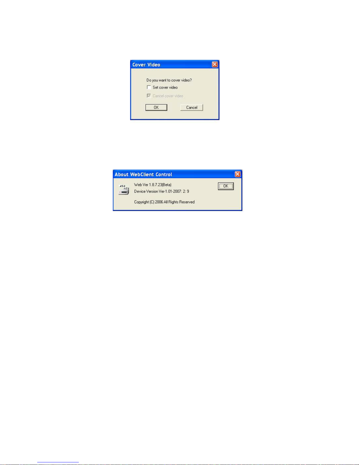
56
Privacy mask zone is a four-sided section in the screen.
You can drag this section to your desired location and resize its size.
Draw a √ before the checkbox to activate this function. See figure 6-28.
6-28
6.2.15 About
Here is for you to view version information, program version (BIOS version) and etc.
See figure 6-29.
6-29
 Loading...