

videotronic SN-15AH PPHS Mounting And Operation Instructions
1
Mounting and Operation Instructions
for
Variable High Speed P/T Head
03/03
SN-15AH/PPHS/ALU (Art. No. 560413)

1

GENERAL INFORMATION
-3-
Contents
General Information
Safety Precautions 4
Items Delivered 4
Product Description 5
Accessories and Additional Devices 5
Mounting and Connecting the Camera Station
Camera Station 6
System Control with Video Matrix 6
Mounting the Camera Station 7
Connecting the Telemetry Receiver 8
Connection Cable Type I and II 9
Connecting the Video Signal 9
Connecting the Operating Voltage 12
Connecting the Interface 12
Configuring the Camera Station
Setting the Device Address 13
Selection of Correct Payload 14
Selection of Interface 14
Preset Call via Alarm Inputs 15
Change from (F)BAS to Y/C Operation 15
Activating Current Loop/RTS, CTS (RS-232) 15
Configuring the Tracking Mode 16
Commissioning
Configuring the Vertical Axle 19
Correlation of Speed 19
Setting the Horizontal and Vertical Limit Switches 20
Operating the Camera Station
Operating the Camera Station 21
Operating the Motor with Presets 21
Calling a Camera Preset 21
Storing a Camera Preset 21
Programming the Panorama Function 22
Programming the position hold time during panorama mode 22
Programming the home Position 23
Connecting the KB-485 24
Address Selection of SN-15AH/PPHS 25
Keyboard KB-485 26
Exhibit
Technical Specifications 28
Description of RS232 Interface 29
RS -232 Interface in Tracking Mode 30
Programming Control Sequences 31
Crimping a BNC plug 32
Your notes 33

GENERAL INFORMATION
-4-
Dear Customer!
By selecting this videotronic product you have decided to use a professional device
which guarantees highest quality and reliability.
We like to thank you very much for your confidence and kindly ask you to read the
following instructions carefully before operating in order to be able to take full
advantage of all quality features regarding this product.
Safety Precautions
1. Read the following instructions carefully before operating the unit to avoid eventual
damages by improper installation.
2. Installation may only be done by authorised personnel in compliance with the local
safety regulations.
3. Operate the P/T unit with 230 V/AC, 50 Hz (+/- 10%) power supply via the
attached power supply unit in the junction box.
4. Before installing the device, the end positions of the P/T unit have to be adjusted
to the local conditions at site!
5. If any liquid or solid matter should get into the housing, disconnect the unit from
power supply and have it checked by your authorised dealer before re-using.
6. Never use the device for a purpose other than designated.
7. If the unit is not being used for an extended period of time, disconnect from power
supply.
8. Repairs may only be carried out by authorised technicians.
9. The product has left the factory in perfect condition. To ensure proper and secure
function, the user must follow all safety information and warnings attached to these
instructions.
Items delivered
• Variable high speed pan/tilt motor incl. integrated telemetry receiver boards.
• 26-pin system cable to connect a VIDEOTRONIC VI ‘System Camera’.
• Service junction box (IP65) for connection of all necessary cable junctions and
power supply.
• 2 x lateral cover for mounting bracket.

GENERAL INFORMATION
-5-
Product Description
The new videotronic variable high speed pan/tilt motor is a breakthrough compared to
conventional pan/ tilt motors available to date. It combines elegant design with excellent
and outstanding performance. Among individual and customised programs and control
functions you have very accurate panorama steering (pre-set tour through up to 100
different pre-programmed positions) with variable speed adjustment of up to 90°/sec.
during pre-set call with a backlash of < 0.1°. The motor is using high precision stepper
motors and self-locking worm gears, resistant to wear. Due to self-lubricating gears the
unit is suitable for continuous operation. Regular service and/ or maintenance are not
necessary.
The integrated RS-232 serial interface allows the unit to be adapted to any existing or
future telemetry system. The integrated RS-485 control circuit board makes the motor
fully compatible with the Videotronic BUSTRONIC RS-485 network. In combination
with the Videotronic HQ System Camera (colour, mono or colour/mono) the variable
speed is automatically controlled in relation to the zoom position (wide/ tele). This
package embodies the most elegant and sophisticated PTZ camera unit available on
the market.
Accessories and Additional Devices
System Camera’ VI -SWK -40120 ALU/PP
VI -FK-20120 EX/ALU/PP
VI -TRI-Q-20120 ALU/PP
VI -SWK-3080 EX/ALU/PP
VI -FK-3080 EX/ALU/PP
VI-TDN-3080 EX/ALU/PP
Bracket WA-40 BSN (max. 40 kg)
Corner mount EMH-SN
Mounting socket AKS-SN
MOUNTING AND CONNECTING
-6-
Mounting and Connecting the Camera Station
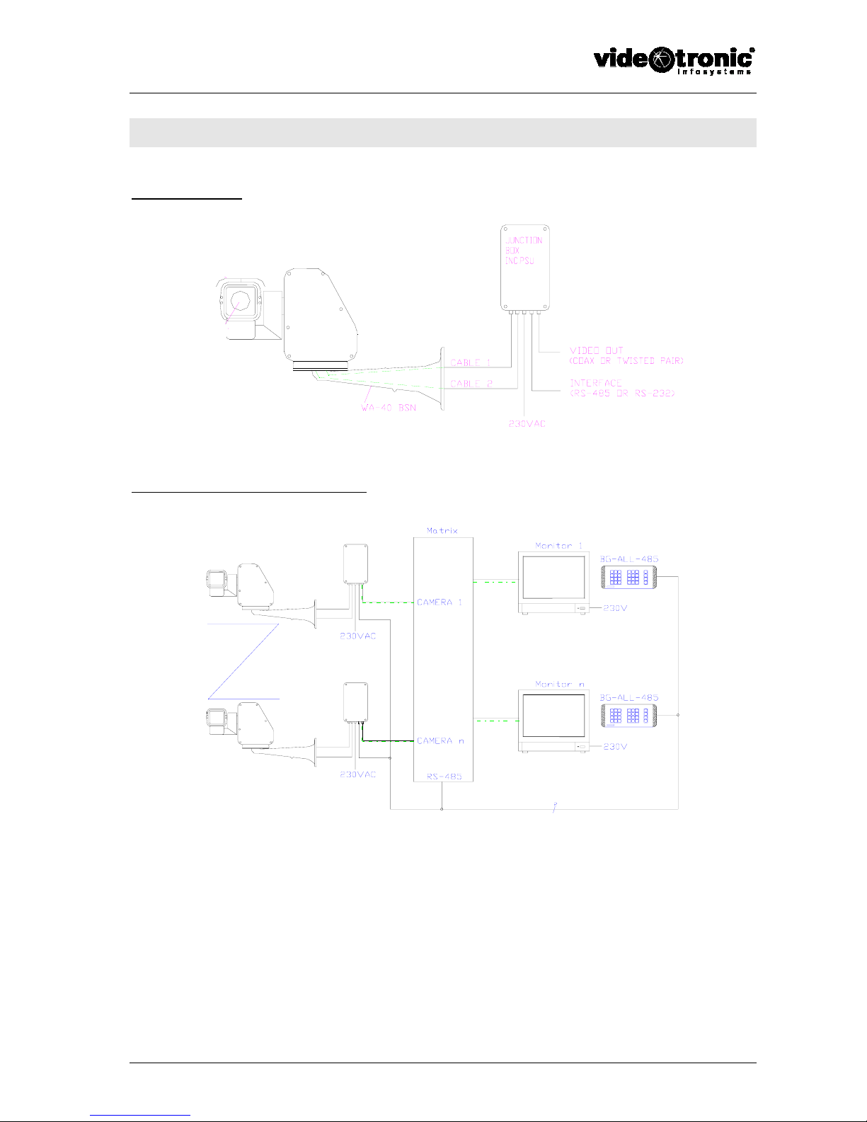
Camera Station
System Control with Video Matrix
Control of the entire system is done over the RS-485 interface of the KB-485 keyboard
using a standard twisted pair telephone cable (shielded). To allow selection of specific
camera stations within the system, all devices in the RS-485 BUS have to have an
individual address.

MOUNTING AND CONNECTING
-7-
Mounting the Camera Station
Attention When installing the camera station please make sure to follow the order
mentioned below.
1. Install the pan/tilt motor to a Videotronic WA-40BSN wall bracket using the
attached installation material (M6 x 20 hex / M6 nut/ M6 washer).
2. Fix the service junction box incl. power supply unit as near to the motor as
possible. The pre-wired connections of the motor have a length of 2,5 metres and
have to be connected to the service junction box after installation.
3. Fix the VI “System Camera” unit to the bracket of the motor using the attached
screws. The camera can also be mounted upside down, depending on the
application.
4. When connecting the system cable, see correct polarity of the cable (PIN 1 =
transparent). Further details are mentioned in the operating instructions of the
system camera. After having installed the system camera, please fix the lateral
covers to the bracket of the motor using 2 screws (M3 x 8).
26-pin system connector (camera connection)
1 heater + 10 zoom - 19 auto focus
2 heater - 11 focus + 20 shutter
3 lanc signal 12 focus - 21 PP +
4 linelock GND 13 GND 22 PP 5 +12 V DC 14 backlight 23 zoom position
6 linelock 15 Y signal 24 focus position
7 GND 16 C signal 25 current loop
8 video 17 NC 26 current loop
9 zoom + 18 NC
MOUNTING AND CONNECTING
-8-
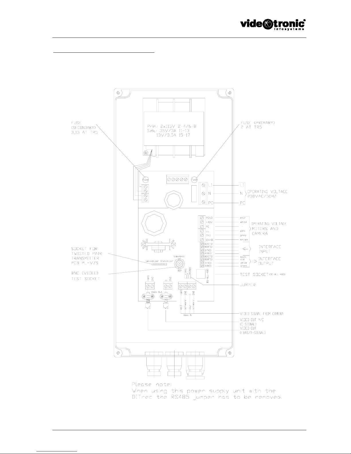
Connecting the Telemetry Receiver

MOUNTING AND CONNECTING
-9-
Connection Cable Type I and II (to pan/tilt motor))
First of all you have to establish connection between motor and service junction box.
Please make sure all connections are done according to the instructions. Wrong
connections might destroy the complete unit. Please run all cables through the
designated PG bolt connectors of the weatherproof junction box and fix the connectors
tightly to avoid damage caused by humidity or leakage.
Cable Type I - Operating Voltage and Interfaces
blue GND (motors)
white + 40 V DC (motor voltage)
rosé linelock synchronisation
grey GND (camera)
brown + 12 V DC (operating voltage)
yellow RS-485 (B) or RS-232 (TxD)
green RS-485 (A) or RS-232 (RxD)
Cable Type II - Video Outputs and Current Loop
black current loop or RS-232 (CTS)
red current loop or RS-232 (RTS)
white video signal (F)BAS or Y (Y/C)
black GND (video signal)
transparent C signal (only during Y/C operation)
black GND (only during Y/C operation)
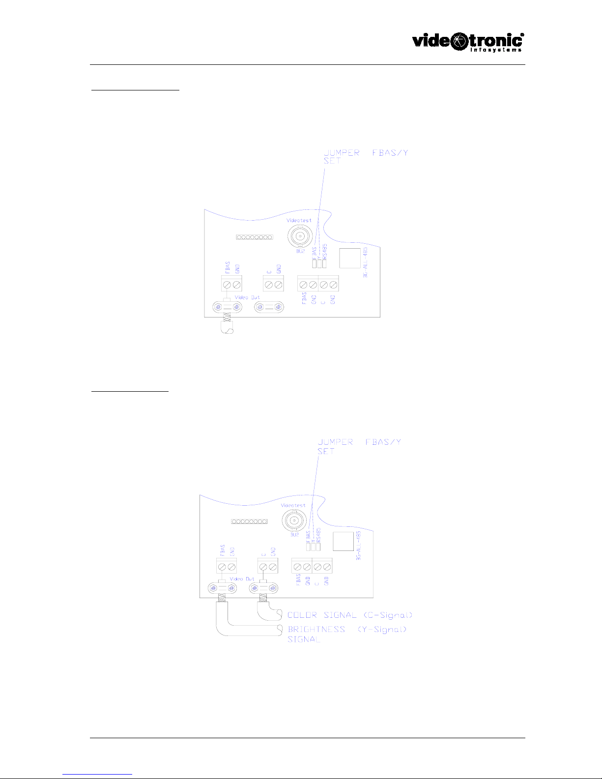
Connecting the Video Signal (F)BAS, Twisted Pair, Y/C Operation
If the pan/tilt motor is being used with a colour camera, the video signal can be
transmitted via standard coaxial cable (FBAS), S-VHS cable (Y/C operation) or twisted
pair cable. If you are using a b/w camera, only coaxial and twisted pair connections are
possible.
For service purposes, the video signal can be tested on a service monitor using the test
socket (video test) on the circuit board. This option allows easy adjustment of all camera
stations directly on site.
MOUNTING AND CONNECTING
-10-
(F)BAS Operation
For standard transmission over coaxial cable connect the cable to the terminal block
„Video Out“ (FBAS/GND) inside the service junction box. The shield of the coaxial cable
has to be fixed with the strain relief clamp.
Set the FBAS / Y jumpers as shown in the drawing!
Y/C - Operation
With a separated transmission of brightness and colour information (Y/C), the quality of
the signal can be considerably improved. The shields of the corresponding cable have
to be fixed with the strain relief clamp..
Set the FBAS / Y jumpers as shown in the drawing!
 Loading...