

Videotek VTM-2000 Installation And Operation Handbook

VTM-2000
Multi-Format SD-SDI Monitor
Installation and Operation Handbook
TWO-YEAR LIMITED WARRANTY
Videotek, Inc. warrants that this product is free from defects in materials and workmanship for a period of two years from the date
of purchase, except for CRTs and LCDs, which are warranted for a period of one year. During this warranty period, Videotek will,
at its option, repair or replace defective products at no charge for the parts or labor. Batteries are not covered in the warranty.
For warranty service or repair, this product must be returned to a service facility designated by Videotek in the original packing or
its equivalent. The purchaser shall insure the product and prepay shipping charges to Videotek, and Videotek shall insure the
product and pay shipping charges to return the product to the purchaser.
The foregoing warranty shall not apply to defects or damage resulting from improper or inadequate maintenance by the
purchaser, connecting the product to incompatible equipment, misuses, operation outside any environmental specification for the
product, improper site preparation or maintenance, or attempts by personnel other than authorized Videotek representatives to
repair or service the product.
No other warranty is expressed or implied. Videotek specifically disclaims the implied warranties of merchantability and fitness for
a particular purpose. The remedies provided by the foregoing warranty are the purchaser's sole and exclusive remedies.
Videotek shall not be liable for any direct, indirect, special, incidental or consequential damages, whether based on contract, tort,
or otherwise.
Printed January 2007
Item #061781 Rev. -
Copyright © 2007 by Videotek, Inc.
All rights reserved.
Contents of this publication may not be reproduced in any form without permission of Videotek, Inc.
This instrument, in whole or in part, may be protected by one or more US (US Patent 6,069,607) or foreign patents or
patent applications.
Specifications subject to change without notice.
___________________________________________________________________________________________________________
IBM is a registered trademark of International Business Machines Corporation
PS2 is a registered trademark of International Business Machines Corporation
Videotek and the Videotek logo are registered trademarks of Videotek, Inc.

VIDEOTEK SOFTWARE LICENSE AND WARRANTY
The software which accompanies this license (the "Software") is the property of Videotek or its licensors and is
protected by copyright law. While Videotek continues to own the Software, you will have certain rights to use the
Software after your acceptance of this license. Except as may be modified by a license addendum which accompanies
this license, your rights and obligations with respect to the use of this Software are as follows:
• You may not:
i. Sublicense, rent, or lease any portion of the Software; or
ii. Reverse engineer, decompile, disassemble, modify, translate, make any attempt to discover the source code
• Limited Warranty:
Videotek warrants that the media on which the Software is distributed will be free from defects for a period of sixty (60)
days from the date of delivery of the Software to you. Your sole remedy in the event of a breach of this warranty will be
that Videotek will replace any defective media returned to Videotek within the warranty period. Videotek does not
warrant that the Software will meet your requirements or that operation of the Software will be uninterrupted or that the
Software will be error-free.
THE ABOVE WARRANTY IS EXCLUSIVE AND IN LIEU OF ALL OTHER WARRANTIES, WHETHER EXPRESS OR
IMPLIED, INCLUDING THE IMPLIED WARRANTIES OF MERCHANTABILITY, FITNESS FOR A PARTICULAR
PURPOSE AND NONINFRINGEMENT. THIS WARRANTY GIVES YOU SPECIFIC LEGAL RIGHTS. YOU MAY HAVE
OTHER RIGHTS, WHICH VARY FROM STATE TO STATE.
• Disclaimer of Damages:
REGARDLESS OF WHETHER ANY REMEDY SET FORTH HEREIN FAILS OF ITS ESSENTIAL PURPOSE, IN NO
EVENT WILL VIDEOTEK BE LIABLE TO YOU FOR ANY SPECIAL, CONSEQUENTIAL, INDIRECT OR SIMILAR
DAMAGES, INCLUDING ANY LOST PROFITS OR LOST DATA ARISING OUT OF THE USE OR INABILITY TO USE
THE SOFTWARE EVEN IF VIDEOTEK HAS BEEN ADVISED OF THE POSSIBILITY OF SUCH DAMAGES.
SOME STATES DO NOT ALLOW THE LIMITATION OR EXCLUSION OF LIABILITY FOR INCIDENTAL OR
CONSEQUENTIAL DAMAGES SO THE ABOVE LIMITATIONS OR EXCLUSION MAY NOT APPLY TO YOU.
IN NO CASE SHALL VIDEOTEK LIABILITY EXCEED THE PURCHASE PRICE FOR THE SOFTWARE. This
disclaimer and limitations set forth above will apply regardless of whether you accept the Software.
• U.S. Government Restricted Rights:
RESTRICTED RIGHTS LEGEND. Use, duplication, or disclosure by the Government is subject to restrictions as set
forth in subparagraph © (1) (ii) of the Rights in Technical Data and Computer Software clause at DFARS 252 227-7013
or subparagraphs © (1) and (2) of the Commercial Computer Software-Restricted Rights clause at 48 CFR 52.227-19,
as applicable, Videotek, Inc., 243 Shoemaker Road, Pottstown, PA 19464.
• General:
This agreement will be governed by the laws of the Commonwealth of Pennsylvania. This Agreement may only be
modified by a license addendum which accompanies this license or by a written document which has been signed by
both you and Videotek. Should you have any questions concerning this Agreement, or if you desire to contact Videotek
for any reason, please write:
Videotek, Inc.
243 Shoemaker Road
Pottstown, PA 19464-6433
of the Software, or create derivative works from the Software
VTM-2000 Installation and Operation Handbook

OPERATOR'S SAFETY SUMMARY
CAUTION — these instructions are for use by qualified personnel only. To reduce
the risk of electric shock, do not perform this installation or any servicing unless you
are qualified to do so. Refer all servicing to qualified service personnel.
To ensure safety:
• The unit should not be exposed to dripping or splashing, and no objects filled with liquids, such as
vases, shall be placed on the unit.
• When the unit is to be permanently cabled, connect the protective ground conductor before making
any other connections.
• Operate built-in units only when they are properly fitted into the system.
• For permanently cabled units without built-in fuses, automatic switches, or similar protective facilities,
the AC supply line must be fitted with fuses rated to the units.
• Before switching on the unit, ensure that the operating voltage set at the unit matches the line
voltage, if appropriate. If a different operating voltage is to be set, use a fuse with the appropriate
rating. Refer to the Installation Instructions.
• Units of Protection Class I with an AC supply cable and plug that can be disconnected must be
operated only from a power socket with protective ground contact:
− Do not use an extension cable—it can render the protective ground connection ineffective.
− Do not intentionally interrupt the protective ground conductor.
− Do not break the protective ground conductor inside or outside the unit or loosen the protective
ground connection; such actions can cause the unit to become electrically hazardous.
• Before opening the unit, isolate it from the AC supply. Then ensure that:
− Adjustments, part replacements, maintenance, and repairs are carried out by qualified personnel
only.
− Safety regulations and rules are observed to prevent accidents.
− Only original parts are used to replace parts relevant to safety (for example, the power on/off
switches, power transformers, and fuses).
• Replaceable fuses can be hazardous when live. Before replacing a fuse, disconnect the AC power
source.
• Use caution when cleaning the equipment; isopropyl alcohol or similar solvents can damage or
remove the labels.
• Observe any additional safety instructions specified in this manual.
These symbols may appear on Videotek equipment:
Explanation of Symbols
VTM-2000 Installation and Operation Handbook

European Restriction on Hazardous Substance (RoHS), and Waste from
Electrical and Electronic Equipment (WEEE) Compliance
About This Document
This document provides information concerning Leitch Technology International, Inc. compliance with EU
Directive 2002/95/EC and EU Directive 2002/96/EC.
Restriction on Hazardous Substances (RoHS) Directive
Directive 2002/95/EC—commonly known as the European Union (EU) Restriction on Hazardous
Substances (RoHS)—sets limits on the use of certain substances found in electrical and electronic
equipment. The intent of this legislation is to reduce the amount of hazardous chemicals that may leach
out of landfill sites or otherwise contaminate the environment during end-of-life recycling. The Directive
takes effect on July 1, 2006, and it refers to the following hazardous substances:
• Lead (Pb)
• Mercury (Hg)
• Cadmium (Cd)
• Hexavalent Chromium (Cr-V1)
• Polybrominated Biphenyls (PBB)
• Polybrominated Diphenyl Ethers (PBDE)
In accordance with this EU Directive, all Leitch Technology products sold in the European Union will be
fully RoHS-compliant and “lead-free.” (See the Leitch Web site, www.leitch.com, for more information on
dates and deadlines for compliance.) Spare parts supplied for the repair and upgrade of equipment sold
before July 1, 2006 are exempt from the legislation. Leitch equipment that complies with the EU directive
will be marked with a RoHS-compliant symbol, as shown in Figure 1.
Figure 1. RoHS Compliance Symbol
WASTE FROM ELECTRICAL AND ELECTRONIC EQUIPMENT (WEEE)
DIRECTIVE
The European Union (EU) Directive 2002/96/EC on Waste from Electrical and Electronic Equipment
(WEEE) deals with the collection, treatment, recovery, and recycling of electrical and electronic waste
products. The objective of the WEEE Directive is to assign the responsibility for the disposal of associated
hazardous waste to either the producers or users of these products. Effective August 13, 2005, producers
or users will be required to recycle electrical and electronic equipment at end of its useful life, and must
not dispose of the equipment in landfills or by using other unapproved methods. (Some EU member
states may have different deadlines.)
In accordance with this EU Directive, Leitch Technology International, Inc. and other companies selling
electric or electronic devices in the EU will affix labels indicating that such products must be properly
recycled.
(See the Leitch Web site, www.leitch.com, for more information on dates and deadlines for compliance.)
Contact your local Leitch sales representative for information on returning these products for recycling.
Leitch equipment that complies with the EU directive will be marked with a WEEE-compliant symbol, as
shown in Figure 2.
VTM-2000 Installation and Operation Handbook

Figure 2. WEEE Compliance Symbol
VTM-2000 Installation and Operation Handbook

Blank Page
VTM-2000 Installation and Operation Handbook

Contents
Section 1 ♦ Introduction
Video Standards Supported.................................................................................................. 1-1
Service and Support.............................................................................................................. 1-3
Section 2 ♦ Installation
Inspecting the Shipment ....................................................................................................... 2-1
Rack Mounting the VTM-2000 .............................................................................................. 2-2
Connecting the VTM-2000 ............................................................................................... 2-3
Ethernet Setup ................................................................................................................. 2-4
Configuring the VTM/TVM Series with the RCU-2000 Remote Control .......................... 2-6
Section 3 ♦ General Operation
Terms .................................................................................................................................... 3-1
Introduction to Operating the VTM-2000 .............................................................................. 3-1
Types of Controls .................................................................................................................. 3-4
Selecting a Pane................................................................................................................... 3-4
Full-Screen Display Selection .......................................................................................... 3-4
Selecting a Video Input .........................................................................................................3-5
Powering Down from the Front Panel ................................................................................... 3-5
Navigating the Pane Setup Menu ......................................................................................... 3-5
Reference......................................................................................................................... 3-6
Pane Overview...................................................................................................................... 3-6
Main Title Bar ................................................................................................................... 3-7
Icons ............................................................................................................................ 3-7
Status Bar ........................................................................................................................ 3-7
The Waveform Display.......................................................................................................... 3-7
Waveform Front Panel Selections ................................................................................. 3-11
Moving the Waveform using the Setup Knobs .......................................................... 3-11
Sweep Button ............................................................................................................ 3-11
Mag Button ................................................................................................................ 3-12
Gain Button................................................................................................................ 3-12
Zoom Button .............................................................................................................. 3-13
Placing the Waveform Display in Line Select Mode.................................................. 3-13
Waveform Pane Menu Selections.................................................................................. 3-14
Filter Selection ........................................................................................................... 3-15
Parade and Overlay Selections ................................................................................. 3-15
Format ....................................................................................................................... 3-16
VTM-2000 Installation and Operation Handbook
i

Contents
Blanking (SD-SDI only).............................................................................................. 3-16
Component Sequence (SD-SDI only) ....................................................................... 3-16
Center Waveform ...................................................................................................... 3-16
Waveform Setup........................................................................................................ 3-16
Utilizing the Vector Display ................................................................................................. 3-17
Controlling the Vector .................................................................................................... 3-22
Gain Button................................................................................................................ 3-22
Zoom Button .............................................................................................................. 3-22
Placing the Vector Display in Line Select Mode....................................................... 3-23
Vector Pane Menu Selections ....................................................................................... 3-23
Standard .................................................................................................................... 3-24
Vector Position .......................................................................................................... 3-24
Center Vector............................................................................................................. 3-24
Vector Setup.............................................................................................................. 3-24
Picture Display .................................................................................................................... 3-25
Alarm Status Display........................................................................................................... 3-26
Audio Display ...................................................................................................................... 3-27
Audio Scales .................................................................................................................. 3-27
Vertical Audio Displays.............................................................................................. 3-28
Expanding the Audio Display......................................................................................... 3-31
Presets ................................................................................................................................ 3-31
Storing Presets .............................................................................................................. 3-31
Recalling Presets ........................................................................................................... 3-31
Preset 4 (Factory Preset)............................................................................................... 3-32
Section 4 ♦ Global Setup Menu Functions
Navigating the Setup Menu................................................................................................... 4-1
Setup Menu and Alarm Tables ............................................................................................. 4-2
Video Format Menu ....................................................................................................... 4-11
Video A, B, C, or D Configure.................................................................................... 4-11
Waveform Setup Menu .................................................................................................. 4-11
Digital Waveform Graticule........................................................................................ 4-11
NTSC Pedestal (or 7.5 IRE Setup)............................................................................ 4-11
PAL Waveform Scale ................................................................................................ 4-11
DC Restore................................................................................................................ 4-11
Waveform Intensity.................................................................................................... 4-11
Waveform Contrast.................................................................................................... 4-12
Persistence ................................................................................................................ 4-12
Attack......................................................................................................................... 4-12
ii
VTM-2000 Installation and Operation Handbook

Contents
Vector Setup Menu ........................................................................................................ 4-12
PAL Overlay............................................................................................................... 4-12
SD I/Q Lines (Component Vector Only) .................................................................... 4-12
Vector Intensity .......................................................................................................... 4-12
Vector Contrast.......................................................................................................... 4-12
Persistence ................................................................................................................ 4-12
Attack......................................................................................................................... 4-13
Audio Setup Menu ......................................................................................................... 4-13
Configure Inputs ........................................................................................................ 4-13
Meter Setup ............................................................................................................... 4-13
AES Validity Bit.......................................................................................................... 4-15
Output Preferences.................................................................................................... 4-15
Display Setup ................................................................................................................. 4-16
Display Colors............................................................................................................ 4-16
Graticule Intensity ...................................................................................................... 4-16
Monitor....................................................................................................................... 4-16
Time Code ................................................................................................................. 4-17
Communications Setup.................................................................................................. 4-17
RCU Port ................................................................................................................... 4-17
IP Configuration ......................................................................................................... 4-17
GPI Output Function .................................................................................................. 4-18
Unit ID........................................................................................................................ 4-19
System Setup Menu....................................................................................................... 4-19
Panel and Preset Lockout ......................................................................................... 4-19
Set Time .................................................................................................................... 4-21
About.............................................................................................................................. 4-22
Section 5 ♦ Alarm Descriptions
Setting Alarms....................................................................................................................... 5-1
Audio Alarms......................................................................................................................... 5-2
Peak Audio....................................................................................................................... 5-2
Loss of Sound .................................................................................................................. 5-2
Video Alarms Digital Descriptions......................................................................................... 5-2
Loss of Carrier.................................................................................................................. 5-2
Digital Gamut ...................................................................................................................5-2
RGB Upper/Lower ....................................................................................................... 5-2
EDH.................................................................................................................................. 5-2
Video Alarms Analog Descriptions........................................................................................ 5-2
Loss of Signal................................................................................................................... 5-2
VTM-2000 Installation and Operation Handbook
iii

Contents
SC/H Phase ..................................................................................................................... 5-2
Analog Gamut .................................................................................................................. 5-3
Peak Upper.................................................................................................................. 5-3
Peak Lower.................................................................................................................. 5-3
Section 6 ♦ Troubleshooting
Cold Starting the VTM-2000 ................................................................................................. 6-1
Cold Start ......................................................................................................................... 6-1
Warm Start....................................................................................................................... 6-2
Cold Start after VFlash..................................................................................................... 6-2
Updating with VFlash ............................................................................................................6-2
Problems, Causes, and Solutions......................................................................................... 6-2
Appendix A ♦ Specifications
Video ..................................................................................................................................... A-1
Audio ..................................................................................................................................... A-2
Control...................................................................................................................................A-3
Display ..................................................................................................................................A-3
Time Code.............................................................................................................................A-4
Magnification......................................................................................................................... A-4
VFlash ................................................................................................................................... A-4
Remote Control..................................................................................................................... A-4
Power Requirements ............................................................................................................A-5
Mechanical ............................................................................................................................ A-5
Environmental .......................................................................................................................A-5
Standard Accessories ...........................................................................................................A-5
Options..................................................................................................................................A-5
Appendix B ♦ Pinouts
Appendix C ♦ RCU-2000 Remote Control Unit
Installing the RCU-2000........................................................................................................C-1
Operating the RCU-2000 ......................................................................................................C-3
Troubleshooting ....................................................................................................................C-3
Specifications ........................................................................................................................C-4
Power Requirements (External Power Supply) ...............................................................C-4
Mechanical.......................................................................................................................C-4
Environmental ..................................................................................................................C-4
Standard Accessories......................................................................................................C-4
Pinouts ..................................................................................................................................C-5
Appendix D ♦ Glossary
iv
VTM-2000 Installation and Operation Handbook

Contents
Index
Figures
Figure 1-1. VTM-2000 Front and Back Panels......................................................................... 1-2
Figure 2-1. Mounting the VTM-2000 in a Rack ........................................................................ 2-2
Figure 2-2. VTM-2000 Back Panel Connectors........................................................................ 2-3
Figure 2-3. VTM-2000 Dedicated PC Connection.................................................................... 2-4
Figure 2-4. VTM-2000 Network PC Connection....................................................................... 2-5
Figure 2-5. Connecting the RCU-2000 Remote Control Panel to Multiple VTM-2000 Units.... 2-6
Figure 3-1. VTM-2000 Front Panel* ......................................................................................... 3-1
Figure 3-2. Sample Multi-Display ............................................................................................. 3-3
Figure 3-3. Selecting a Pane ....................................................................................................3-4
Figure 3-4. Sample Quad Diagram........................................................................................... 3-6
Figure 3-5. Full-Screen Display Diagram ................................................................................. 3-7
Figure 3-6. Waveform Display Diagram ................................................................................... 3-8
Figure 3-7. RGB and YCBCR Graticule ................................................................................... 3-10
Figure 3-8. RGB and YCBCR Zoom 0 mV Graticule ............................................................... 3-10
Figure 3-9. RGB and YCBCR Zoom 700 mV Graticule ........................................................... 3-10
Figure 3-10. Moving the Waveform ........................................................................................ 3-11
Figure 3-11. Establishing the Sweep Scale............................................................................ 3-12
Figure 3-12. Establishing the Gain ......................................................................................... 3-13
Figure 3-13. Establishing Line Select ..................................................................................... 3-14
Figure 3-14. Vector Display Diagram ..................................................................................... 3-17
Figure 3-15. Vector NTSC Graticule....................................................................................... 3-18
Figure 3-16. Vector NTSC Zoom Upper Left......................................................................... 3-19
Figure 3-17. Vector NTSC Zoom Upper Right ....................................................................... 3-19
Figure 3-18. Vector NTSC Zoom Lower Right ....................................................................... 3-20
Figure 3-19. Vector NTSC Zoom Lower Left.......................................................................... 3-20
Figure 3-20. Vector PAL Zoom Center ................................................................................... 3-21
Figure 3-21. Vector SD with I/Q.............................................................................................. 3-21
Figure 3-22. Establishing the Vector Gain.............................................................................. 3-22
Figure 3-23. Establishing Line Select ..................................................................................... 3-23
Figure 3-24. Picture Display Diagram..................................................................................... 3-25
Figure 3-25. Alarm Status Display Diagram ........................................................................... 3-26
Figure 3-26. Two Bar Graph Display with Lissajous Diagram................................................ 3-29
Figure 3-27. Four Bar Graph with Lissajous Display Diagram ............................................... 3-30
Figure 4-1. Display Color Selection ........................................................................................ 4-16
Figure 4-2. Enter Password Screen ....................................................................................... 4-19
Figure 4-3. Enter New Time Screen ....................................................................................... 4-22
VTM-2000 Installation and Operation Handbook
v

Contents
Figure 4-4. About Screen ....................................................................................................... 4-22
Figure B-1. ANALOG AUDIO IN/OUT 37-pin, Male, D-sub Connector For Audio Option .......B-1
Figure B-2. XGA OUT 15-pin, Female, D-sub Connector ........................................................ B-2
Figure B-3. GPI/TALLY Connector........................................................................................... B-3
Figure B-4. GPI/TALLY Breakout Board................................................................................... B-3
Figure B-5. Remote RJ-11 Control Connector ......................................................................... B-4
Figure B-6. VFlash RJ-45 Connector .......................................................................................B-4
Figure C-1. RCU- 2000 Front and Back Panel Views ..............................................................C-1
Figure C-2. Connecting the RCU to Multiple VTM-2000 ..........................................................C-2
Figure C-3. RCU-2000 TO MAIN UNIT RJ-11 Connector........................................................C-5
Tables
Table 2-1. Parts Required to Rack Mount the VTM-2000 using the DRC-2 ............................ 2-2
Table 2-2. Description of Back Panel Connectors.................................................................... 2-3
Table 3-1. Front Panel Description........................................................................................... 3-1
Table 3-2. Description of Quad Screen Display ....................................................................... 3-3
Table 3-3. Reference menu...................................................................................................... 3-6
Table 3-4. Description of Icons.................................................................................................3-7
Table 3-5. Video Formats and Units of Measure...................................................................... 3-8
Table 3-6. Video Formats and Critical Amplitude Limits .......................................................... 3-8
Table 3-7. Description of Waveform Display Diagram ............................................................. 3-9
Table 3-8. Waveform (Analog) Menu Structure...................................................................... 3-14
Table 3-9. Waveform (Digital) Menu Structure....................................................................... 3-15
Table 3-10. Description of Vector Display Diagram ............................................................... 3-17
Table 3-11. Vector Pane Menu............................................................................................... 3-24
Table 3-12. Description of Picture Display Diagram............................................................... 3-25
Table 3-13. Description of Alarm Status Display Diagram ..................................................... 3-26
Table 3-14. Alarm Status Pane Menu .................................................................................... 3-27
Table 3-15. Description of Two Bar Graph Display with Lissajous Diagram.......................... 3-29
Table 3-16. Description of Four Bar Graph with Lissajous Display Diagram ........................ 3-30
Table 4-1. Setup Menu Tables ................................................................................................. 4-2
Table 4-2. Video Format Menu................................................................................................. 4-3
Table 4-3. Waveform Setup Menu............................................................................................ 4-3
Table 4-4. Vector Setup Menu.................................................................................................. 4-3
Table 4-5. Audio Setup Menu................................................................................................... 4-4
Table 4-6. Audio Alarms Menu ................................................................................................. 4-6
Table 4-7. Video Alarms, Digital Menu..................................................................................... 4-7
vi
VTM-2000 Installation and Operation Handbook

Contents
Table 4-8. Video Alarms, Analog Menu.................................................................................... 4-8
Table 4-9. Display Setup Menu ................................................................................................ 4-9
Table 4-10. Display Colors Menu ............................................................................................. 4-9
Table 4-11. Communications Setup Menu ............................................................................. 4-10
Table 4-12. System Setup Menu ............................................................................................ 4-10
Table 4-13. About Menu ......................................................................................................... 4-10
Table 4-14. Ballistic Specifications with Attack and Decay .................................................... 4-14
Table 6-1. VTM-2000: Problems, Causes, and Solutions ........................................................ 6-2
Table B-1. Pinouts for ANALOG AUDIO IN/OUT Connector and Audio Breakout Board.........B-1
Table B-2. XGA OUT Connector Pinouts .................................................................................B-2
Table B-3. Pinouts for GPI/TALLY Connector and GPI/TALLY Breakout Board......................B-3
Table B-4. Remote RJ-11 Control Connector Pinouts .............................................................B-4
Table B-5. VFlash RJ-45 Connector Pinouts............................................................................B-4
Table C-1. Description of RCU-2000 Back Panel Connectors.................................................C-1
Table C-2. RCU-2000: Problems, Causes, and Solutions .......................................................C-3
Table C-3. Pinouts for RCU-2000 TO MAIN UNIT Connector .................................................C-5
VTM-2000 Installation and Operation Handbook
vii

Contents
Blank Page
viii
VTM-2000 Installation and Operation Handbook

Section 1 ♦ Introduction
The Videotek VTM-2000 is a Muti-format On-Screen Monitor with waveform
monitor, vectorscope, picture, and alarm status. It is a 19” rackmounted unit that
accepts two NTSC or PAL composite video signals, two SD-SDI video signals, and an
external analog reference video signal. The display presents the image carried by the
selected video input as a real-time, full-motion picture. Front panel user controls allow
for various display and selection modes.
In addition, the VTM-2000 also accepts the audio option VTM-A3-OPT 1, which is the
Advanced Audio Analysis Option with bargraphs and lissajous. With the
VTM-A3-OPT 1 up to four audio channels can be viewed simultaneously. There are
two analog stereo inputs, four AES/EBU inputs, and 16 channels of embedded audio.
It also contains analog monitoring outputs of up to four channels simultaneously.
The VTM-2000 seamlessly integrates into any broadcast, post-production, camera
maintenance, satellite or cable facility, and is the ultimate choice for quality control,
troubleshooting, or compliance checking applications.
*
US Patents 6,069,607, 6,532,024, and 6,828,981. UK Patent 2,330,475. Other US and foreign patents pending.
Features include:
• Dual SD-SDI inputs with auto detection
• Dual composite analog inputs with auto detection
• Reference input
• XGA, High Resolution, output
• Three user presets and one factory preset
• Compact 1RU configuration
• Input standards: SMPTE 259M-C, NTSC, and PAL
Video Standards Supported
The VTM-2000 supports the following video standards:
For SD:
• 525/59.94
• 625/50
For analog:
• NTSC
• PAL
The VTM-2000 front and back panels are illustrated in Figure 1-1.
VTM-2000 Installation and Operation Handbook
1-1
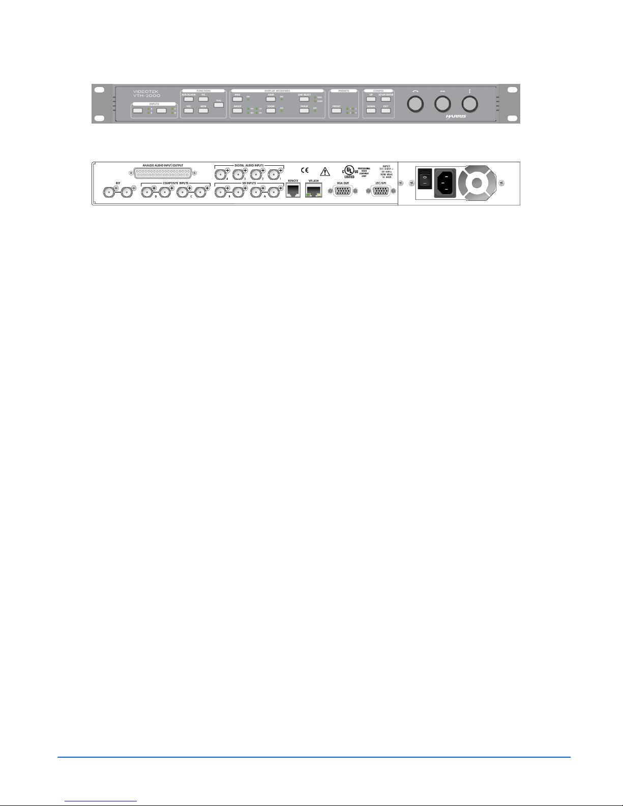
Figure 1-1. VTM-2000 Front and Back Panels
Front Panel
Back Panel
Introduction
1-2
VTM-2000 Installation and Operation Handbook

Service and Support
For service support, telephone the Customer Service Department at 610-327-2292. If
the problem cannot be resolved over the telephone and the instrument must be shipped
to Videotek for service or repair:
• Obtain a Return Authorization (RA) number from the Videotek Customer Service
Department.
• Attach a tag to the unit with:
− Your company name, address, and telephone number
− The name of the contact person at your company
− The RA number
− The unit serial number
− An explanation of the problem
• To prevent shipping damage, pack the unit the same way Videotek had packed it.
If possible, use the original packing materials in the original shipping container.
• Ship the unit to:
Videotek, Inc.
243 Shoemaker Road
Pottstown, PA 19464-6433
Attn: Service Dept.
VTM-2000 Installation and Operation Handbook
1-3

Introduction
Blank Page
1-4
VTM-2000 Installation and Operation Handbook

Section 2 ♦ Installation
This section provides information about inspecting, installing, and configuring the
VTM-2000.
Inspecting the Shipment
Before installing the VTM-2000, inspect the box and the contents. Report any damage
to the shipper and telephone the Videotek Customer Service Department for service
and support (see Section 1, “Service Support”).
NOTE: Refer to the enclosed packing sheet for the latest list of items that are supplied with the unit.
The box contains the following:
• One VTM-2000
• One VTM-2000 Installation and Operation Handbook
• One 75Ω terminator
• One detachable power cord
• One breakout connector (for LTC/GPI)
• If the audio option has been purchased, one additional breakout connector or 37-pin
connector is also supplied
Save the box and packing material for any future shipping requirements.
VTM-2000 Installation and Operation Handbook
2-1
Installation
Rack Mounting the VTM-2000
When selecting the permanent mounting location for the VTM-2000, ensure that the
flow of air to the ventilation holes on the sides of the chassis is not obstructed. Rack
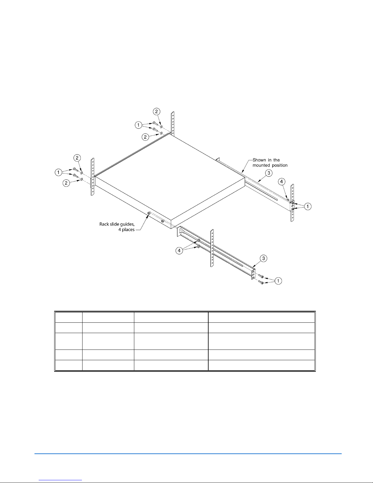
mounting the VTM-2000 is illustrated in Figure 2-1. The parts required to rack mount
the VTM-2000 are listed in Table 2-1.
Figure 2-1. Mounting the VTM-2000 in a Rack
Table 2-1. Parts Required to Rack Mount the VTM-2000 using the DRC-2
Key Item Number Quantity Description
1
2
3
4
831030 8 (4 for each side) Hardware screw, 10-32 x 3/4 PP black
831019 4 (2 for each side) Hardware washer, nylon, .437 x .195 x
.032
832076 2 (1 for each side) Metal rack extension bracket
831060 4 (2 for each side) Hardware knut 10-32
Attach the rack extension brackets to the back of the rack. Once the extension brackets
are in place, guides on the VTM-2000 unit enable it to slide in and out of rack
extension brackets for easy access and removal.
2-2
VTM-2000 Installation and Operation Handbook
Installation
Connecting the VTM-2000
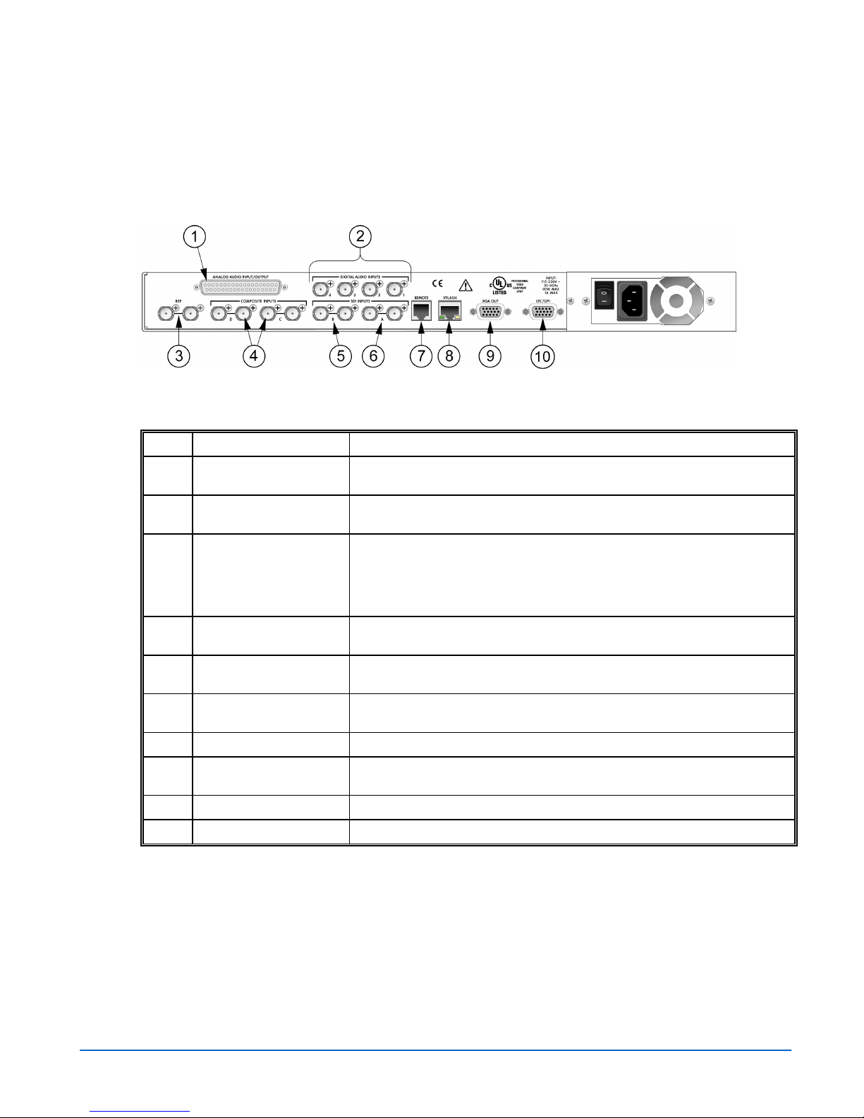
The back panel connectors are illustrated in Figure 2-2, and the function of each
connector is described in Table 2-2.
Figure 2-2. VTM-2000 Back Panel Connectors
Table 2-2. Description of Back Panel Connectors
Key Label Description
ANALOG AUDIO
1
IN/OUT
DIGITAL AUDIO INPUT
2
1, 2, 3, 4
REF Female BNC connectors that connect to an external NTSC/PAL reference
3
INPUTS C (IN, OUT), D
4
(IN, OUT)
INPUT B (IN, OUT) Female BNC looping SD SDI input and output connector. Termination
5
INPUT A (IN, OUT) Female BNC looping SD SDI input and output connector. Termination
6
7
REMOTE RJ11 socket to connect to the remote control panel.*
VFlash RJ45, female, 10/100 BaseT Ethernet connection to be used with a PC
8
9
XGA OUT 15-pin, high-density, female, D-sub connector for XGA output.*
10
LTC/GPI 15-pin, high-density, female, D-sub connector for LTC, and GPI input.*
*See Appendix C, “Pinouts,” for the connections.
Optional 37-pin, D-sub, male connector for analog audio inputs and outputs.
The supplied breakout board can be used for solderless connections.*
Optional female BNC connectors for AES/EBU audio input.
signal (video or blackburst) from which the horizontal and vertical sync, and
the color burst frequency for the VTM-2000 will be derived if EXT has been
selected as the REF source. If these connectors are not looped through,
then the unused connector must be terminated at 75Ω.
Female BNC looping analog composite input and output connectors.
Termination required.
required.
required.
running the VFlash program.*
VTM-2000 Installation and Operation Handbook
2-3
Installation
Ethernet Setup
1. Prior to the VTM-2000 Network configuration, obtain Transmission Control
Protocol/Internet Protocol (TCP/IP) addresses from the System Administrator or
from the Internet Service Provider (ISP).
These addresses are:
• A static IP address (unless Dynamic Host Configuration Protocol (DHCP) will
be used)
• A Subnet Mask
• An optional Gateway IP
Be sure to record all addresses. The Gateway address is only needed if the
VTM-2000 is routed to an outside network.
Record the addresses:
VTM-2000 Interface Static IP Address
VTM-2000 Interface Subnet Mask
Gateway IP Address
2. Identify a host PC to configure and test the VTM-2000.
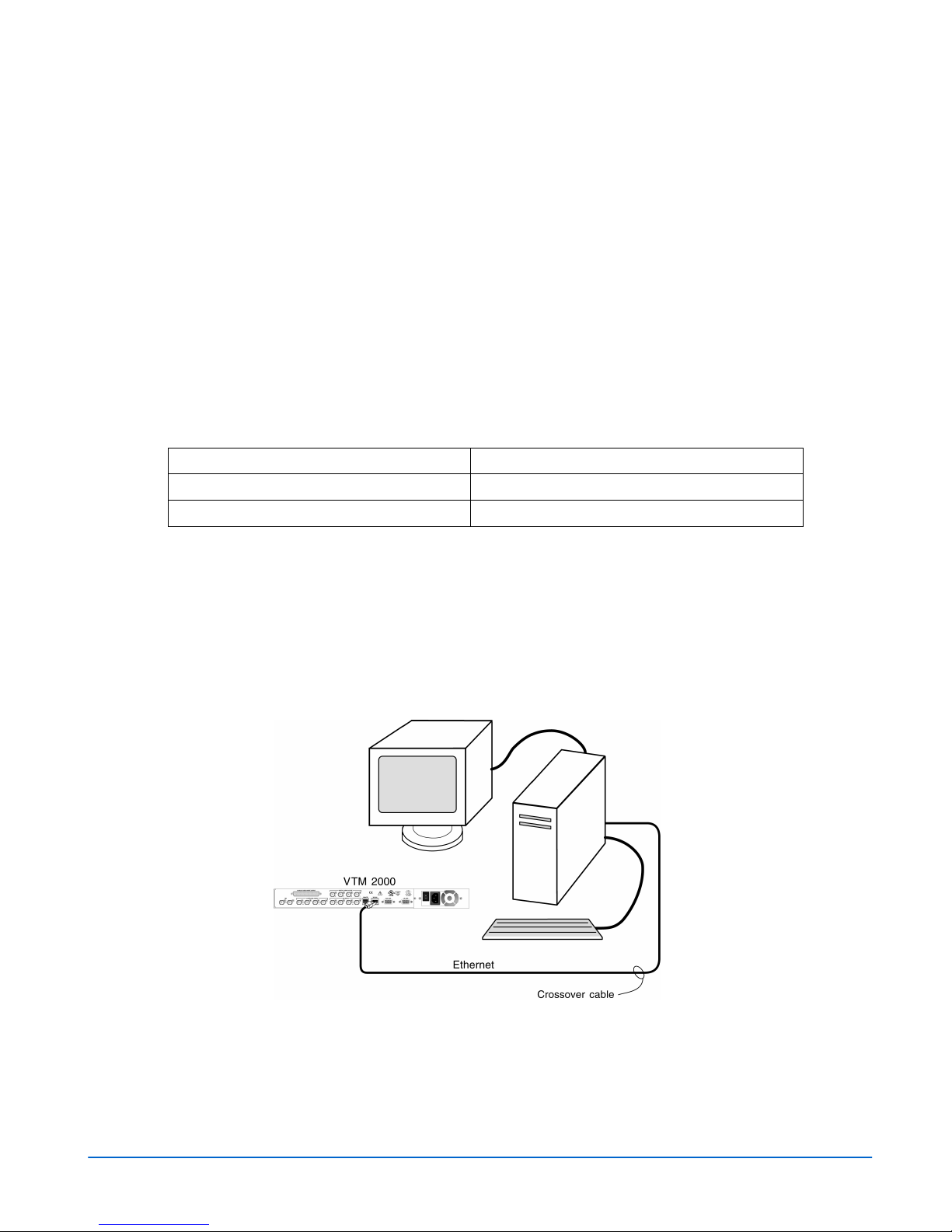
3a. For a dedicated PC connection, connect the host PC with a network card to the
“VFLASH” connector on the back panel of the VTM-2000, using a CAT5
crossover cable (not included). See Figure 2-3.
Figure 2-3. VTM-2000 Dedicated PC Connection
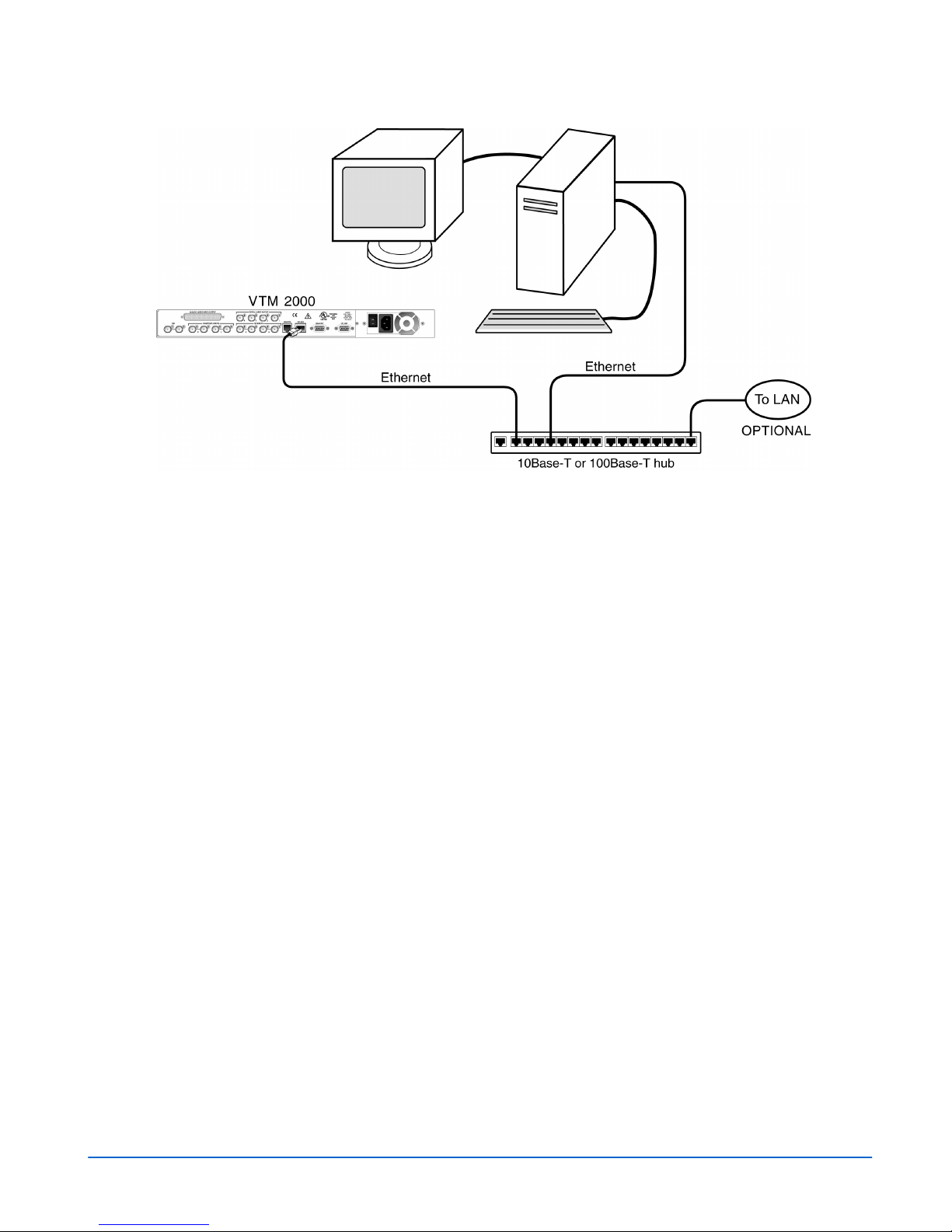
3b. For a network connection, connect the network hub to the back panel of the
VTM-2000 using a CAT5 network cable (not included). See Figure 2-4.
2-4
VTM-2000 Installation and Operation Handbook
Installation
Figure 2-4. VTM-2000 Network PC Connection
4. Ethernet Configuration
a) Press the SETUP/ENTER button on the VTM front panel.
b) Press the UP or DOWN button to highlight the COMMUNICATIONS menu,
and then press the SETUP/ENTER button to enter the submenu.
c) Press the UP or DOWN button until the IP CONFIGURATION submenu is
highlighted.
d) Press the SETUP/ENTER button to enter the IP CONFIGURATION submenu.
e) (If using DHCP) Turn the LEFT/RIGHT knob or press the SETUP/ENTER
button to highlight DHCP. Press the UP or DOWN button to toggle the state to
ON. Turn the LEFT/RIGHT knob or press the SETUP/ENTER button to
highlight ACCEPT, and then press SETUP/ENTER. The IP Address, Subnet
mask, and Gateway is retrieved from the DHCP server.
(If not using DHCP) Press the UP or DOWN button to change the value in the
first IP address box, and press the SETUP/ENTER button to highlight the next
value. Repeat for the remainder of the IP Address, Subnet Mask, and Gateway.
To avoid conflicts, the static IP Address, Subnet Mask, and Gateway should be
obtained from the System Administrator.
f) Press SETUP/ENTER button or turn the LEFT/RIGHT knob to highlight
ACCEPT, and press SETUP/ENTER to accept the entered values.
g) Press the EXIT button to exit the submenu.
VTM-2000 Installation and Operation Handbook
2-5
Installation
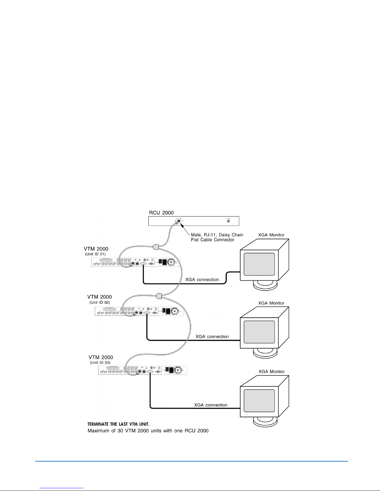
Configuring the VTM/TVM Series with the RCU-2000 Remote
Control
For the following configurations, the interconnecting cables can be extended using
electronic distribution. There are two ways to configure the VTM-2000 Series with the
RCU-2000 remote control:
• One RCU-2000 connected to one VTM-2000 unit using the REMOTE port.
• One RCU-2000 connected to multiple VTM-2000 using a multidrop cabling
adaptor and straight through cable using RJ-11 connectors (not a standard
telephone wire) that connects to the REMOTE ports on the back of the VTM-2000
units and to the TO MAIN UNIT connector on the back of the RCU. All
VTM-2000 units must have unique unit IDs. The unit ID is the identification
number of the VTM-2000 units, and can be set to any number within a range of 1
to 99 in the COMMUNICATIONS menu. The unit IDs should be different than the
identification numbers of other units in the same system configuration. The
REMOTE port must be terminated on the last VTM-2000 unit, as shown in
Figure 2-5. The flat cable shown in Figure 2-5 is a straight through cable.
Figure 2-5. Connecting the RCU-2000 Remote Control Panel to Multiple VTM-2000 Units
2-6
VTM-2000 Installation and Operation Handbook
Section 3 ♦ General Operation
Terms
Pane: One quadrant in a four-quadrant screen.
Display: The output that appears on the XGA monitor.
Quad: Screen that contains four panes.
Full: Full-screen display of the selected pane (non quad).
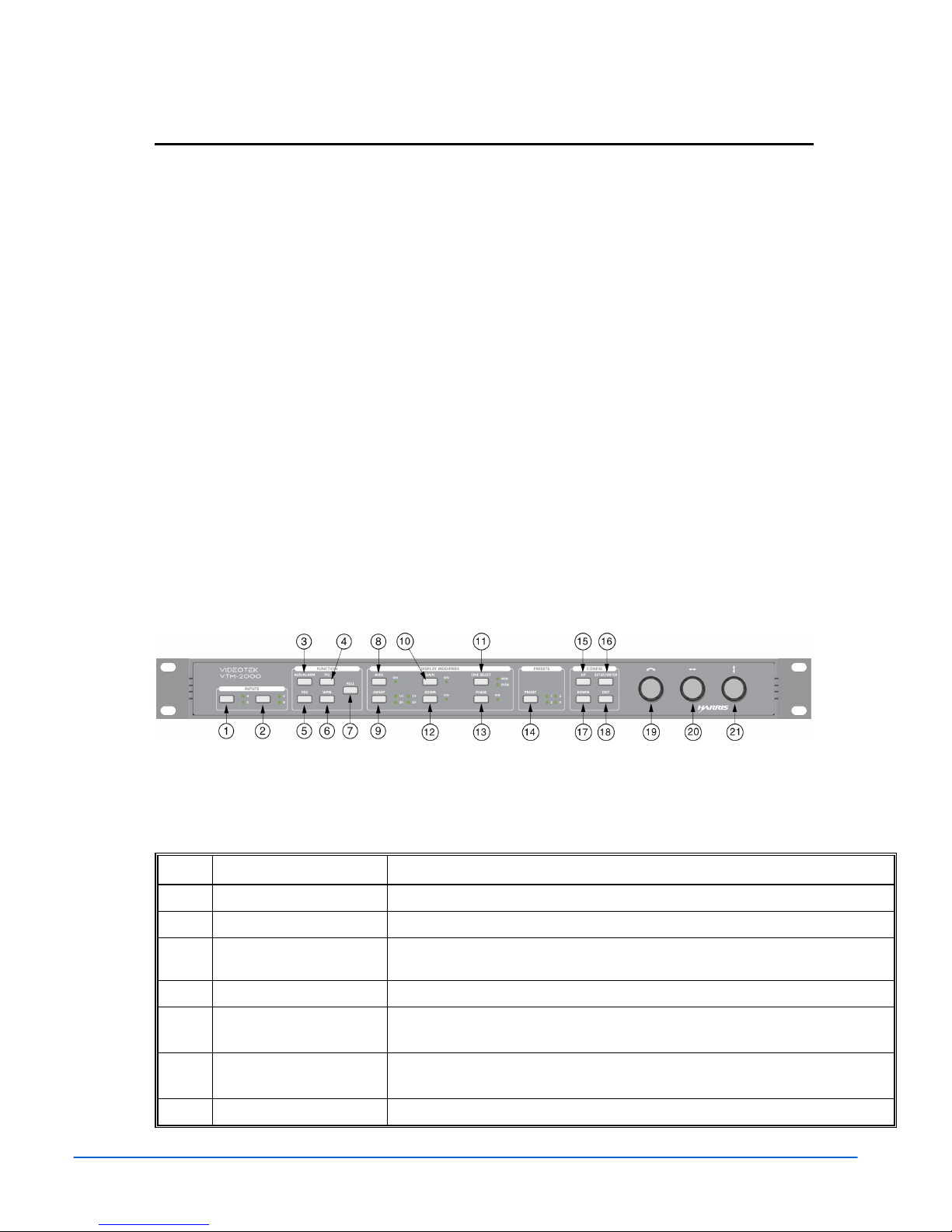
Introduction to Operating the VTM-2000
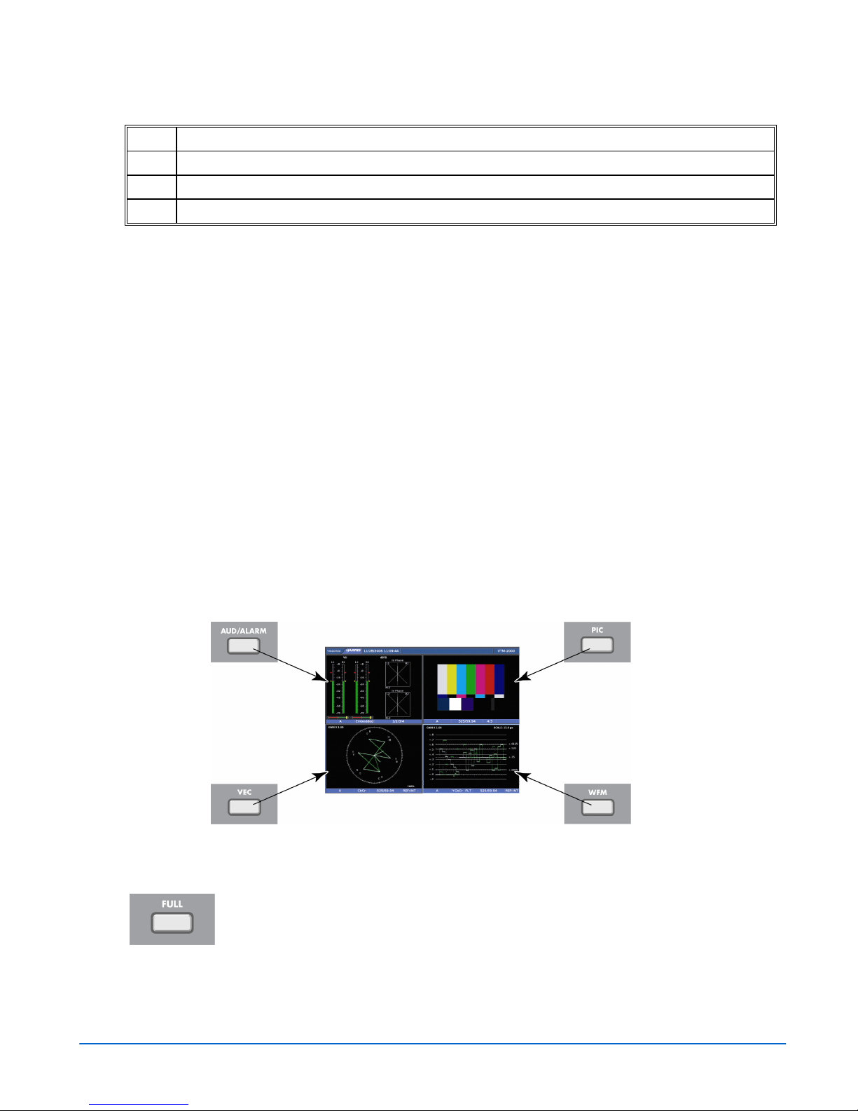
The VTM-2000, shown in Figure 3-1 and described in Table 3-1, can display four
panes on the screen, in standard quad mode each of which provides a fixed display of
waveform (lower-right), vector (lower-left), audio and alarm status (upper-left), and
picture (upper-right). A sample quad screen with the lower-right pane selected is
shown in Figure 3-2.
Certain buttons function differently according to the selected pane. Once the pane is
selected, more detailed settings can be configured. This section focuses on the
operation of the VTM-2000 according to the selected display.
Figure 3-1. VTM-2000 Front Panel*
*NOTE: Pressing and holding some of the function buttons will activate menus for additional
functionality.
Table 3-1. Front Panel Description
Key
1 INPUTS A and B
2 INPUTS C and D
3 AUDIO/ALARM
Label Description
Press to select SDI input A or SDI input B.
Press to select composite input C or composite input D.
Press to highlight and switch between the Audio and Alarm pane. When audio
is installed, the Audio pane is the default pane.
4 PIC
5 VEC
6 WFM
7 FULL
Press to highlight the Picture pane
Press to highlight the Vector pane
Press and hold to access the Vector Pane menu.
Press to highlight the Waveform pane
Press and hold to access the Waveform Pane menu.
Press to show a full-screen display of the selected pane.
VTM-2000 Installation and Operation Handbook
(Table continues on next page)
3-1

General Operation
Table 3-1. Description of Front Panel Controls Illumination (continued)
Key Label Description
8 MAG
9 SWEEP
10 GAIN
11 LINE SELECT
12 ZOOM
13 PHASE
Press to cycle through the magnifications for the waveform display, either a
normal horizontal sweep or a sweep that has been horizontally magnified. The
magnifications are shown below:
Component 1H Sweep magnifications: 15.0 µS, 3.0 µS, and 1.5 µS
Component 1V Sweep magnifications:15.0 ms, 3.0 ms, 1.5 ms, and 0.6
ms
Composite 1H Sweep magnifications: 5.0 µS, 1.0 µS, 0.5 µS
Composite 2H Sweep magnifications: 10.0 µS, 2.0 µS, 1.0 µS
Composite 1V Sweep magnifications: 5.0 ms, 1.0 ms, 0.5 ms, and 0.2 ms
Composite 2V Sweep magnifications: 10.0 ms, 2.0 ms, 1.0 ms, and 0.4 ms
Press to cycle the waveform between 1H (one horizontal line of video), 2H (two
successive lines of composite video only), 1V (one vertical field of video), or 2V
(two successive fields of composite video only).
Press to cycle through the vertical gain of 1, 2.5, or 5 for the waveform and
vector display.
Press to cycle the line select display to ODD, EVEN, or OFF.
Press to cycle through the various zoom displays for the selected waveform or
vector pane or Audio (if installed). Zoom mode is indicated with “ZOOM” at the
top of the selected pane.
(For Composite analog video only). When in Composite, the default LED is on.
Line Select will turn the LED off. Press the PHASE button to turn it back on.
Turn the CURVED ARROW knob to control the phase of the vector.
14 PRESET
15 UP
16 SETUP/ENTER
17 DOWN
18 EXIT
19 CURVED ARROW
KNOB
20 LEFT/RIGHT ARROW
KNOB
21 UP/DOWN ARROW
KNOB
Press to step through and select the four preset memories. If a preset does
not exist, the Preset is skipped. Locked presets cannot be stored until they are
unlocked.
Press to step up through the Global Setup or pane menu.
Press to enter the Global Setup menu or a submenu when the Global Setup or
Pane menu is displayed.
Press to move down through the Global Setup or Pane menu.
Press to exit the submenu, Pane menu, or Global Setup menu.
Rotate the knob to rotate the composite vector phase, or change the line
number when line select is enabled.
Rotate the knob to move the menu (Global or Pane menu) cursor up and
down.
Rotate the knob to move the waveform left and right.
Rotate the knob to move the menu (Global or Pane menu) cursor left and
right.
Rotate the knob to move the waveform up and down.
Rotate the knob to move the menu (Global or Pane menu) cursor up and
down.
3-2
VTM-2000 Installation and Operation Handbook
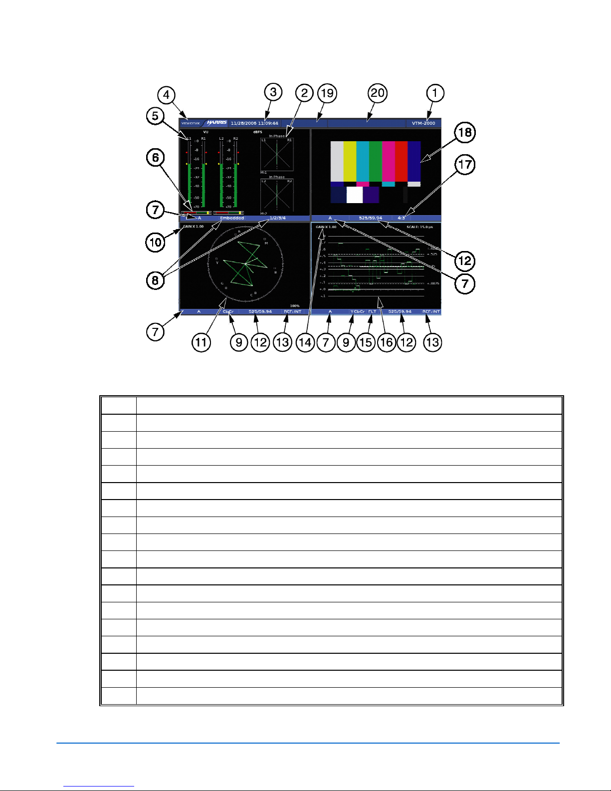
Figure 3-2. Sample Multi-Display
General Operation
Table 3-2. Description of Quad Screen Display
Key Description
1
Model identification
2
Lissajous (X, Y) display of the audio input meter.
3
Date and time of internal clock.
4
Company name.
5
Audio meters
6
Audio phase bar.
7
Indicates the input selection
8
Indicates the Audio format and input channels
9
Indicates the format selection.
10
Vector Gain indication
11
Vector display of the selected input.
12
Indicates the detected or selected video standard.
13
Indicates the reference source
14
Waveform gain indication
15
Indicates the Filter selection.
16
Waveform of selected input.
17
Indicates the aspect ratio of the picture.
VTM-2000 Installation and Operation Handbook
(Table continues on next page)
3-3
General Operation
Table 3-2. Description of Quad Screen Display (continued)
Key Description
18
Displays the picture for the selected input.
19
Icon location
20
Latest alarm displayed (yellow indicates the current alarm, blue indicates the alarm was resolved)
Types of Controls
The VTM-2000 is controlled in three ways:
• Display Modifiers: controls on the front panel that adjust the parameters that are
frequently used.
• Pane Menu Settings: Pop-up menus within a pane that are used to control the
parameters for the individual pane.
• Global Setup Menu Settings: Setup menu parameters that affect the entire unit.
The Setup menu is accessed by pressing the SETUP/ENTER button. See Section 4
for the Global Setup menu and the Global Setup menu selections.
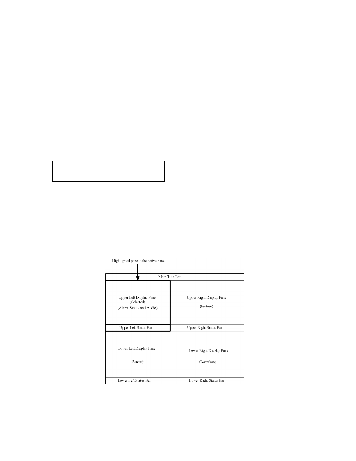
Selecting a Pane
When multiple panes are displayed, only one pane can be selected at a time. The active
pane is highlighted with a bright colored border. Press the desired function button to
select the active pane to be configured, as shown in Figure 3-3.
Figure 3-3. Selecting a Pane
Full-Screen Display Selection
Press the FULL button in the function group to show a full-screen view
of a selected pane. The full-screen display encompasses the entire
screen. No other pane is displayed. Press the FULL button again to
return to the Quad view.
3-4
VTM-2000 Installation and Operation Handbook

General Operation
Selecting a Video Input
Press the Input buttons to select input A, B, C, or D. When an input is selected,
pressing another input button will change to the new input from the previous input.
Powering Down from the Front Panel
Press and hold the EXIT and SETUP/ENTER buttons simultaneously until the four
Preset LEDs are illuminated. The power is removed from the system except for the
front panel. Push any button to repower the VTM-2000.
Navigating the Pane Setup Menu
NOTE: A function button can be pressed to exit from the pane menu. If a different function than the
displayed function is pressed, the highlighted pane will change to the selected function pane.
Use the NAVIGATION buttons or the SETUP POSITION knobs to navigate the Pane
menu. The SETUP POSITION knobs and Navigation buttons are described below:
Press to exit the menu. Press to exit the submenu.
Press to select a menu item or open a menu or submenu.
Press to move up in the menu or submenu.
Press to move down in the menu or submenu.
Rotate the knob to move the menu cursor up and down or to change
a value or condition in a menu.
Rotate the knob to enter or exit the submenus.
Rotate the knob to move the menu cursor up and down or to change
a value or condition in a menu.
VTM-2000 Installation and Operation Handbook
3-5
General Operation
Reference
Press and hold an input button to display and change the Internal or External reference
selection. The default reference selection is Internal. To change the reference
selection:
1. Press and hold the INPUT button to access the Reference pane menu. Table 3-3
shows the Reference menu selections.
2. When REFERENCE is highlighted, press the SETUP/ENTER button (or rotate the
RIGHT/LEFT NAVIGATION knob) to open the menu selections.
3. Press the UP or DOWN button (or rotate the UP/DOWN NAVIGATION knob) to
select the reference, and press the SETUP/ENTER button.
4. Press EXIT twice to exit the menu.
Table 3-3. Reference menu
REFERENCE
INTERNAL (Default)
EXTERNAL
Pane Overview
There are two screens for the VTM-2000: full-screen display or Quad (4 display
panes). Even if the screen is full screen or quad, the pane contains the Main Title Bar,
the display, and the status bar. A diagram of the quad display is shown in Figure 3-4.
A diagram of the full-screen display is shown in Figure 3-5.
Figure 3-4. Sample Quad Diagram
3-6
VTM-2000 Installation and Operation Handbook
 Loading...