

Page 1

MANUALE D’USO
---------------------------------------------------------------------------------------------------------------------------------------------------------
OPERATING INSTRUCTIONS
---------------------------------------------------------------------------------------------------------------------------------------------------------
MANUEL D’INSTRUCTIONS
---------------------------------------------------------------------------------------------------------------------------------------------------------
BEDIENUNGSANWEISUNG
Page 2

Page 3
MANUALE
D’USO
Page 4

Page 5

INDICE
1 INTRODUZIONE .......................................................................................................................................................3
1.1 Contenuto dell’imballaggio..................................................................................................................................3
1.2 Cosa contiene questo manuale ..........................................................................................................................3
1.3 Convenzioni tipografiche.....................................................................................................................................3
2 PRECAUZIONI DI SICUREZZA................................................................................................................................4
3 DATI DI MARCATURA .............................................................................................................................................5
4 DESCRIZIONE DELLA CUSTODIA EXH.................................................................................................................6
4.1 Dispositivo protezione vetro................................................................................................................................6
4.2 Campo di utilizzo.................................................................................................................................................6
5 INSTALLAZIONE ......................................................................................................................................................7
5.1 Apertura dell’imballaggio.....................................................................................................................................7
5.2 Controllo della marcatura....................................................................................................................................7
5.3 Installazione della telecamera.............................................................................................................................8
Collegamento della custodia.....................................................................................................................................8
6 MESSA IN SERVIZIO................................................................................................................................................9
7 MANUTENZIONE....................................................................................................................................................10
8 RISOLUZIONE DI PROBLEMI ...............................................................................................................................11
9 CARATTERISTICHE TECNICHE CUSTODIA .......................................................................................................11
10 SPECIFICHE MASSIME DELLE TELECAMERE COMPRESE DI OTTICA INSTALLABILI..............................11
11 DIMENSIONI CUSTODIA......................................................................................................................................12
12 CARATTERISTICHE TECNICHE DISPOSITIVO PROTEZIONE VETRO ...........................................................13
13 APPENDICE: CODIFICA ANTIDEFLAGRANTE .................................................................................................14
14 APPENDICE: SCHEMA ELETTRICO ..................................................................................................................16
Il produttore declina ogni responsabilità per eventuali danni derivanti da un uso improprio delle apparecchiature
menzionate in questo manuale; si riserva inoltre il diritto di modificarne il contenuto senza preavviso. Ogni cura
é stata posta nella raccolta e nella verifica della documentazione contenuta in questo manuale: tuttavia il
produttore non può assumersi alcuna responsabilità derivante dall’utilizzo della stessa. Lo stesso dicasi per
ogni persona o società coinvolta nella creazione e nella produzione di questo manuale.
Pag. 1 MNVCEXH_0702
Page 6

Per informazioni e assistenza clienti:
HEADQUARTERS ITALY FRANCE
VIDEOTEC S.p.A.
Via Friuli, 6
I-36015 SCHIO (VI) Italy
Tel. +39 0445 697411
Fax +39 0445 697414
[email protected]
www.videotec.com
VIDEOTEC FRANCE S.A.R.L.
Voie du Futur - Zac des Portes
27100 Val de Reuil, France
Tel. +33 2 32094900
Fax +33 2 32094901
[email protected]
www.videotec.com
UK / IRELAND
VIDEOTEC UK SALES
Tel. / Fax +44 (0)1353 775438
[email protected]
www.videotec.com
U.S.A. / CANADA
VIDEOTEC SECURITY, Inc.
The Lower level South Suite
The Ottilio Office Complex I
555 Preakness Ave.
TOTOWA, NJ 07512 - USA
Tel. +1 973 5950788
Fax +1 425 6484289
[email protected]
www.videotec.us
ASIA PACIFIC
VIDEOTEC (HK) Ltd
Unit 2,8/F, Vanta Industrial
Centre
21-33 Tai Lin Pai Road
Kwai Chung, NT, Hong Kong
Tel. +852 2333 0601
Fax +852 2311 0026
[email protected]
www.videotec.com.hk
Pag. 2 MNVCEXH_0702
Page 7
1 Introduzione
1.1 Contenuto dell’imballaggio
• 1 custodia antideflagrante
• 1 manuale d’uso
Alla consegna del prodotto verificare che l’imballo sia integro e non abbia segni evidenti di cadute o abrasioni.
In caso di evidenti segni di danno all’imballo contattare immediatamente il fornitore.
Controllare che il contenuto sia rispondente alla lista del materiale sopra indicata.
1.2 Cosa contiene questo manuale
In questo manuale sono descritte le custodie della serie EXH, con le particolari procedure di installazione,
configurazione e utilizzo. E’ necessario leggere attentamente questo manuale, in modo particolare il capitolo
concernente le norme di sicurezza, prima di installare ed utilizzare il ricevitore.
1.3 Convenzioni tipografiche
Nel presente manuale si fa uso di diversi simboli grafici, il cui significato è riassunto di seguito:
Rischio di scosse elettriche; togliere l’alimentazione prima di procedere con le operazioni, se non é
espressamente indicato il contrario.
Rischio di esplosione. Leggere attentamente per evitare pericoli di esplosione.
L’operazione é molto importante per il corretto funzionamento del sistema: si prega di leggere
attentamente la procedura indicata, ed eseguirla secondo le modalità previste.
Descrizione delle caratteristiche del sistema: si consiglia di leggere attentamente per comprendere le
fasi successive.
Pag. 3 MNVCEXH_0702
Page 8

2 Precauzioni di sicurezza
La custodia risulta conforme alle normative vigenti alla pubblicazione del presente manuale per quanto
concerne gli apparecchi e sistemi di protezione destinati a essere utilizzati in atmosfera potenzialmente
esplosiva, la compatibilità elettromagnetica ed i requisiti generali.
Si desidera tuttavia garantire gli utilizzatori (tecnico installatore e operatore) specificando alcune avvertenze per
operare nella massima sicurezza:
• Assicurarsi che tutti i dispositivi siano adatti per l’applicazione e l’ambiente per cui sono stati progettati.
• Assicurarsi che i dispositivi collegati siano completamente compatibili e adatti all’uso.
• Controllare che le temperature di esercizio siano compatibili con i dispositivi.
• Accertarsi di installare i dispositivi in maniera tale da garantire la sicurezza dell’impianto e del personale
addetto all’installazione.
• Scegliere la postazione di installazione in modo che sia sufficientemente solida da sostenere il peso del
dispositivo, considerando anche aspetti ambientali particolari come esposizione a vento forte.
• Si raccomanda di utilizzare solo staffe o accessori consigliate per l'installazione.
• Accertarsi che il dispositivo sia fissato in maniera solida ed affidabile.
• Dato che la scelta della superficie di montaggio è a cura dell'utente non si forniscono viti per il fissaggio
sicuro del dispositivo alla superficie. È responsabilità dell'installatore utilizzare viti adatte allo scopo specifico
richiesto.
• L’installazione e la manutenzione dell’apparecchio (e dell’intero impianto di cui esso fa parte) deve essere
effettuata da personale tecnico adeguatamente qualificato e lavorare secondo le norme nazionali per la
sicurezza del personale.
• Utilizzare degli utensili adeguati. Degli utensili specifici possono essere richiesti, per motivi di installazione,
in relazione al luogo in cui il dispositivo viene installato.
• Assicurarsi che l'installazione soddisfi le specifiche locali.
• Questo dispositivo deve essere installato fuori dalla portata dell'utente o di chiunque ne possa entrare a
contatto casualmente.
• Collegare ad una linea di alimentazione corrispondente a quella indicata sulle etichette di marcatura (vedere
il successivo capitolo Dati di marcatura).
• Prima di spostare o effettuare interventi tecnici sull’apparecchio, disinserire l‘alimentazione.
• L’apparecchio deve essere aperto soltanto da personale tecnico qualificato e in atmosfera non esplosiva. La
manomissione dell’apparecchio fa decadere i termini di garanzia.
• Non permettere l’uso dell’apparecchio a bambini o incapaci.
• L’apparecchio si considera disattivato soltanto quando l’alimentazione é disinserita e i cavi di collegamento
con altri dispositivi sono stati rimossi.
• Prima dell’alimentazione del dispositivo installare un dispositivo di protezione nell’impianto elettrico
dell’edificio.
• Si raccomanda all'utente di non installare all'interno del dispositivo qualsiasi apparecchiatura che generi
radiazioni pericolose.
• Per l’assistenza tecnica rivolgersi esclusivamente al personale tecnico autorizzato.
• Conservare con cura il presente manuale per ogni futura consultazione.
Questo dispositivo deve essere collegato a terra!
Pag. 4 MNVCEXH_0702
Page 9
3 Dati di marcatura
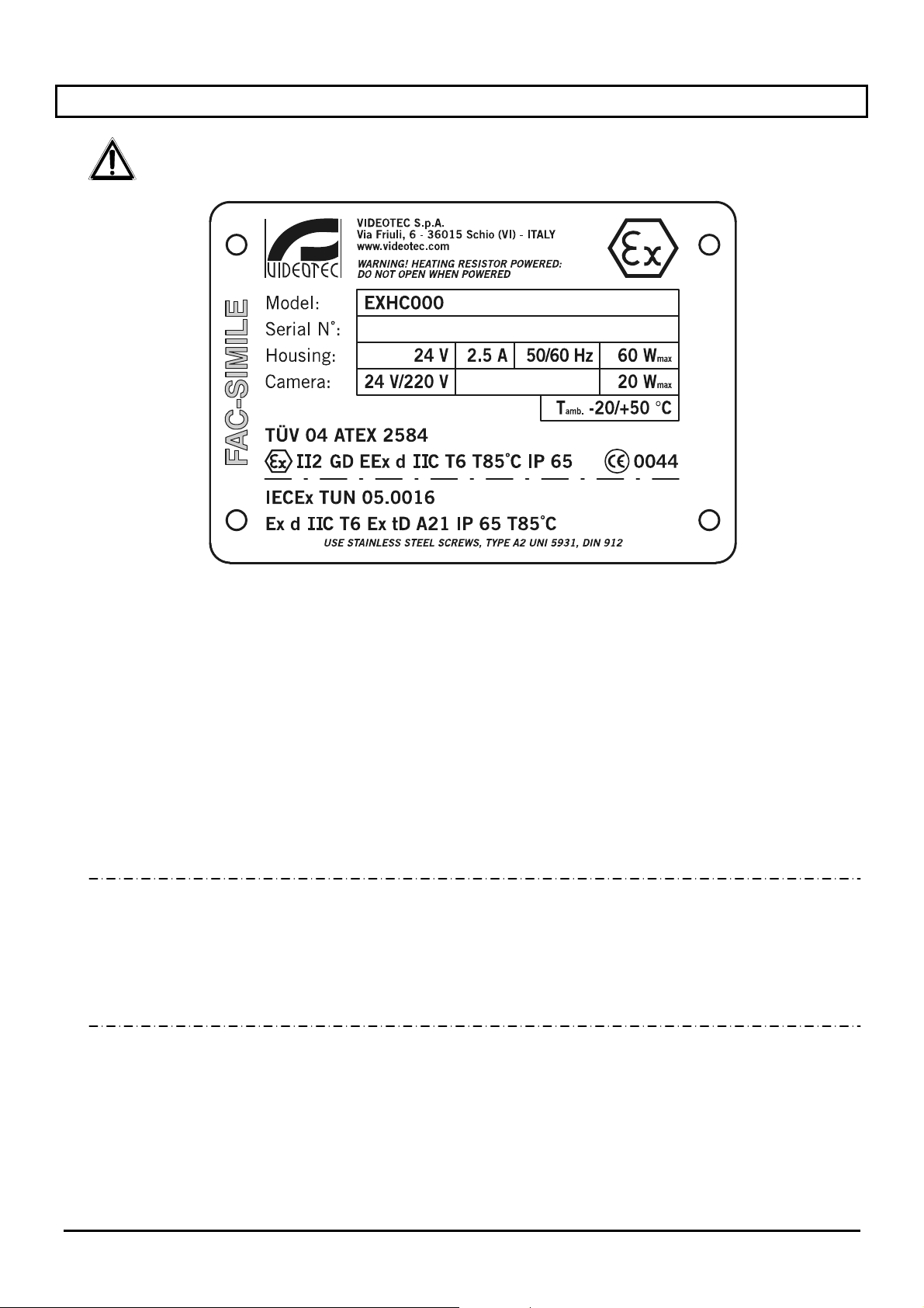
Sul custodia serie EXH sono riportate le seguenti informazioni:
• Simbolo
• Nome e indirizzo del costruttore
• Codice di identificazione del modello
• Numero di serie
• Custodia:
• Tensione d’alimentazione (V)
• Corrente assorbita (A)
• Frequenza (Hz)
• Consumo custodia (W)
• Telecamera:
• Tensione d’alimentazione (V)
• Consumo massimo (W) – (i dati riportati per la telecamera si riferiscono alle caratteristiche di tensione e
• Temperatura ambiente di utilizzo riferita al codice di identificazione del modello
• Numero del certificato ATEX
• Classificazione del tipo di zona, metodo di protezione e classe di temperatura per le quali è
ammesso l'impiego di questo prodotto secondo la direttiva ATEX
• Grado di protezione IP
• Marcatura CE
• Numero dell’organismo notificato che ha rilasciato il certificato ATEX
• Numero del certificato IECEx
• Classificazione del tipo di zona, metodo di protezione e classe di temperatura per le quali è
ammesso l'impiego di questo prodotto secondo la normativa IECEx
Prima dell’installazione controllare se le caratteristiche di alimentazione e di protezione del dispositivo
corrispondono a quelle richieste. L’uso di apparecchi non idonei può portare a gravi pericoli per la sicurezza del
personale e dell’impianto.
b
consumo massimo ammesso per il funzionamento della stessa)
Pag. 5 MNVCEXH_0702
Page 10

4 Descrizione della custodia EXH
La custodia antideflagrante della serie EXH è stata progettata per consentire l'utilizzo di telecamere operanti in
ambienti industriali in cui vi è la probabilità che si manifestino atmosfere esplosive dovute a gas, vapori, nebbie
o miscele di aria o polveri.
Le custodie EXH sono realizzate in massiccia fusione in lega di alluminio Anticorodal del gruppo AlSi7Mg EN
AC-42000 la cui composizione chimica è definita dalla norma UNI EN 1706.
Secondo il modello, tutti gli elementi sono verniciati con polveri in forno o trattati con particolari rivestimenti che
offrono un’eccellente resistenza ai raggi ultravioletti, alla nebbia salina e agli agenti inquinanti presenti
nell’atmosfera.
Sono costruite secondo quanto previsto dalla direttiva 94/9/CE ATEX e i protocolli IEC 60079-0:2000, IEC
60079-0:2001, IEC 61241-1:2004.
II corpo camera è costituito da un tubo cilindrico, dotato di flangia che alloggia un robusto vetro trasparente;
dalla parte opposta al vetro é presente un'ulteriore flangia che, oltre a chiudere il cilindro, sostiene la piastra per
il fissaggio della telecamera. Il grado di protezione IP65 è assicurato anche da due pressacavi 3/4” GAS per
l’inserimento di cavi di servizio con un diametro da 14 mm a 17 mm.
L’impiego di telecamere termiche, in grado di rilevare l’emissione di calore, richiede l’utilizzo di uno speciale
filtro sul frontale della custodia. La sua struttura, composta in prevalenza da Germanio, garantisce le stesse
caratteristiche di resistenza e di sicurezza del vetro standard.
Questa versione di custodia è costruita secondo quanto previsto dalla direttiva 94/9/CE Atex.
La custodia può essere inoltre dotata dei seguenti accessori:
• tettuccio parasole (EXHS);
• staffa con snodo per il fissaggio a parete (EXWBJ);
4.1 Dispositivo protezione vetro
Le custodie antideflagranti della serie EXH possono essere equipaggiate con il dispositivo di protezione vetro,
installato sull’apertura frontale della custodia. Esso è costituito da una flangia di raccordo con la custodia, una
flangia di chiusura e da un corpo centrale antideflagrante contenente un robusto vetro trasparente, un motore in
corrente continua alimentato a 24VDC, due avvolgitori ed una pellicola trasparente in Mylar, installata di fronte
al vetro. Il motore, attraverso 4 pignoni conici dentati, pilota un avvolgitore per il recupero della pellicola sporca,
mentre l’altro avvolgitore rilascia la pellicola pulita. Il motore è controllato remotamente tramite un contatto ONOFF a due fili (un comune ed un + 24VDC).
L'unità di controllo del dispositivo protezione vetro è fornita dal cliente!
La pellicola di Mylar trasparente consente circa 350 passi di avanzamento. Infatti quando è sporca l’operatore
attiverà il motore, facendo avanzare la pellicola sino ad ottenere un’immagine pulita (il passo per consentire lo
scorrimento completo della pellicola sporca è di circa 50 mm). La fine del nastro viene segnalata mediante
contrassegni stampati sugli ultimi 50 cm di pellicola.
L’avanzamento della pellicola potrà avvenire anche automaticamente in maniera temporizzata tramite un
opportuno sistema di controllo (escluso dalla fornitura).
Per sostituire la pellicola aprire la flangia frontale ed estrarre gli avvolgitori. Sostituire la pellicola sporca con una
pulita.
4.2 Campo di utilizzo
L'impiego della custodia EXH è definito per l'utilizzo in postazione fissa per la sorveglianza di zone con
atmosfera potenzialmente esplosiva classificate 1-21 o 2-22, mediante telecamera installata dall'utente al suo
interno.
• La custodia EXH è costruita e certificata in accordo con la direttiva 94/9/CE ATEX e i protocolli IEC 60079-
0:2000, IEC 60079-0:2001, IEC 61241-1:2004 che ne definiscono il campo di applicazione ed i requisiti
minimi di sicurezza.
Pag. 6 MNVCEXH_0702
Page 11
5 Installazione
La fase di installazione deve essere effettuata solo da personale tecnico qualificato.
Effettuare i collegamenti e prove in laboratorio prima dell'installazione nel sito.
Utilizzare degli utensili adeguati.
Le seguenti procedure sono da effettuare in assenza di alimentazione, se non diversamente
indicato.
Un dispositivo di protezione adeguato deve essere installato nell'impianto elettrico prima
del dispositivo.
Non superare le prestazioni specificate.
Non sostituire le viti della custodia con altre di tipo diverso.
Eseguire tutte le connessioni in atmosfera non esplosiva.
5.1 Apertura dell’imballaggio
Se l’imballaggio non presenta evidenti difetti (dovuti a cadute o abrasioni anomale), procedere al
controllo del materiale in esso contenuto, secondo la lista fornita al paragrafo Contenuto dell’imballo al
capitolo Introduzione.
I materiali d’imballo sono costituiti interamente da materiale riciclabile. Sarà cura del tecnico installatore
smaltirli secondo le modalità di raccolta differenziata o comunque secondo le norme vigenti nel paese di
utilizzo.
5.2 Controllo della marcatura
Prima di procedere con l’installazione controllare se il materiale fornito corrisponde alle
specifiche richieste, esaminando le etichette di marcatura, secondo quanto descritto al capitolo
Descrizione della marcatura.
Non effettuare per nessun motivo alterazioni o collegamenti non previsti in questo manuale: l’uso di
apparecchi non idonei può portare a gravi pericoli per la sicurezza del personale e dell’impianto.
Pag. 7 MNVCEXH_0702
Page 12
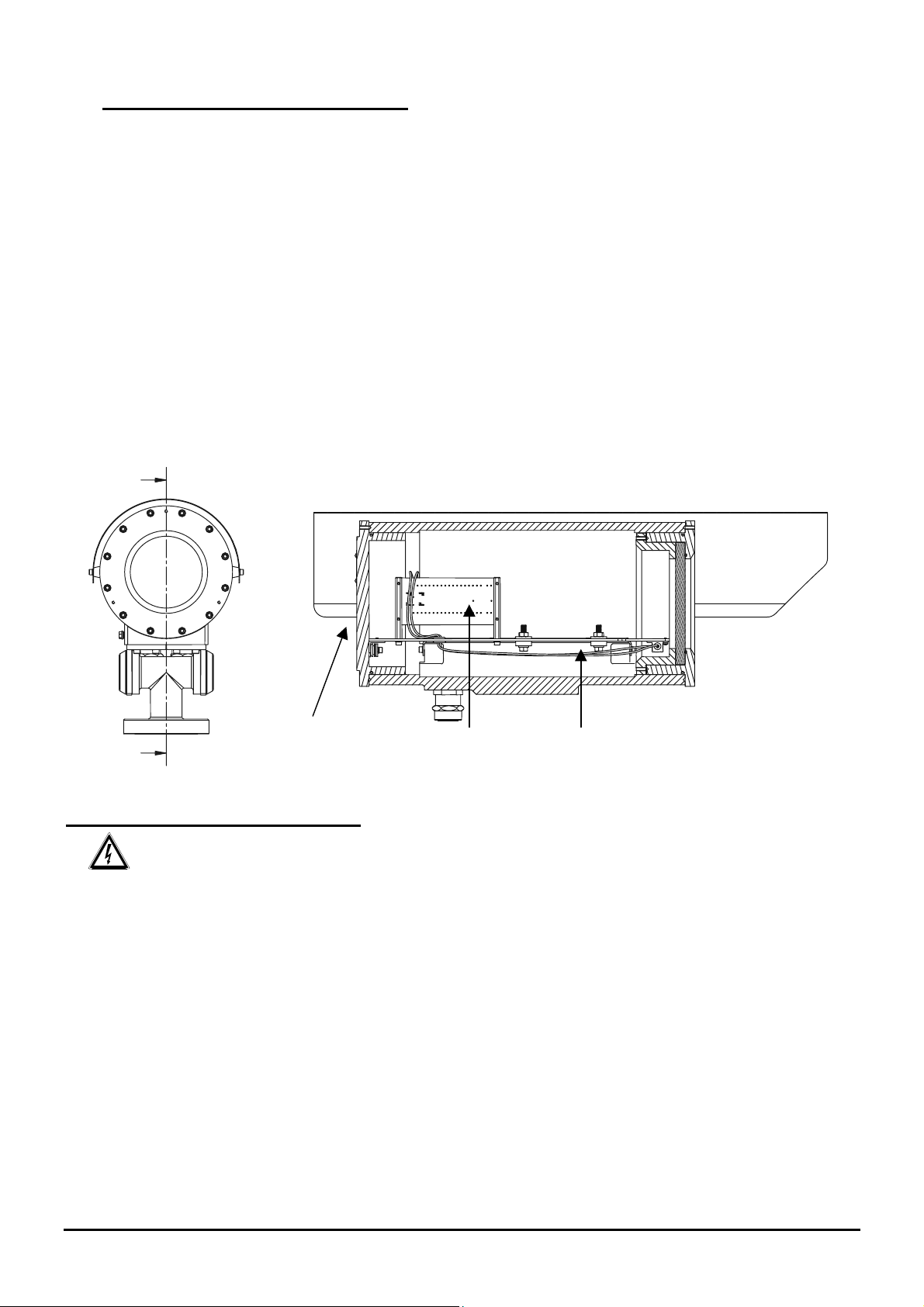
5.3 Installazione della telecamera
Si raccomanda all'installatore di non utilizzare dispositivi che eccedano dalle specifiche!
Si raccomanda all'installatore di non utilizzare dispositivi che generino radiazioni pericolose!
La flangia posteriore sulla custodia è dotata di 12 viti M6. Inoltre è dotata di 3 viti disposte a 120° per facilitare
l'estrazione della flangia stessa. Infatti una volta svitate dalla flangia le viti con filetto M6, avvitando le 3 viti a
120° (un giro alla volta, a rotazione) si agevola l'estrazione della stessa.
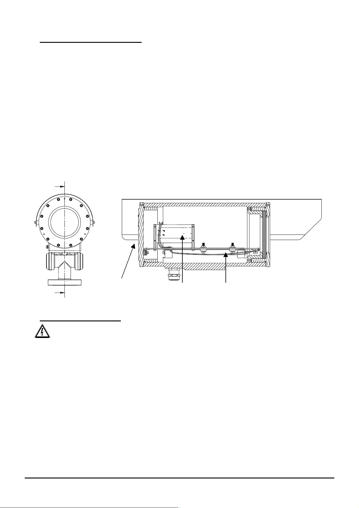
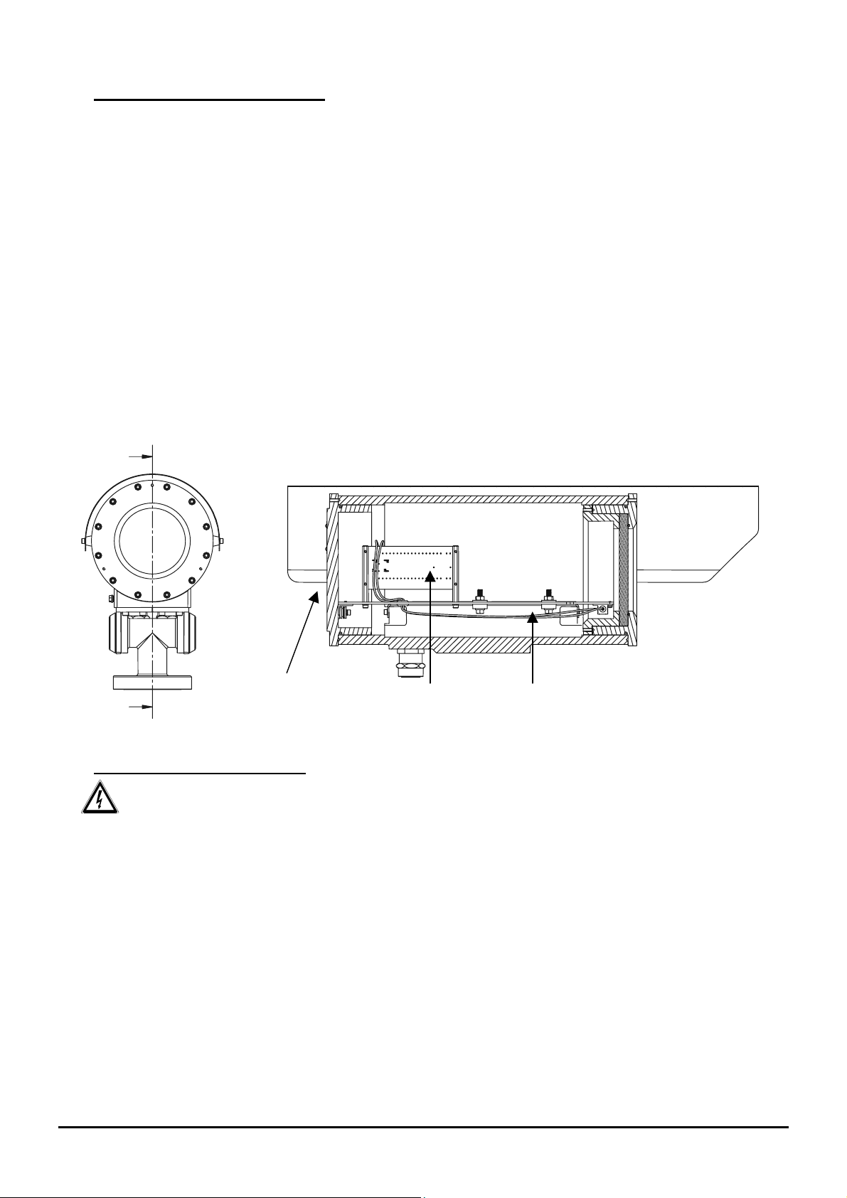
Per installare la telecamera occorre estrarre la flangia di chiusura della custodia, che supporta anche la piastra
di fissaggio della telecamera con la relativa morsettiera. Questa piastra é appoggiata su due guide fissate alla
custodia; togliendo la flangia la piastra scorre sulle guide, consentendo di montare e collegare agevolmente la
telecamera ed i suoi componenti accessori. In fase di installazione si raccomanda di isolare la telecamera dalla
piastra di supporto utilizzando gli appositi distanziali isolanti forniti a corredo.
Per installare la custodia viene utilizzato l'apposito snodo, dotato di 4 fori M6 disposti a 90°, ed eventualmente
la staffa, che si fissa mediante 4 fori M8.
(Per i particolari fare riferimento all'immagine riportata di seguito e allo schema elettrico in appendice.)
Chiudere correttamente la flangia dopo l'installazione della telecamera. Si raccomanda una coppia di serraggio
delle 12 viti di chiusura pari a 12.5 Nm.
Flangia
Morsettiera
Piastra fissaggio telecamera
Collegamento della custodia
Attenzione: prima di effettuare le seguenti operazioni assicurarsi che la tensione della linea sia corretta.
Per effettuare il collegamento della custodia alla linea utilizzare cavi adatti all'impiego in atmosfere
potenzialmente esplosive, eseguire le seguenti operazioni:
• collegare i cavi alla custodia tramite i pressacavi in dotazione;
• effettuare i collegamenti con la telecamera e ottica;
• dare alimentazione all’unità;
• eseguire prove di funzionamento.
Pag. 8 MNVCEXH_0702
Page 13
6 Messa in servizio
Prima di eseguire la messa in servizio si raccomanda di:
• Leggere attentamente e completamente il presente manuale d'uso;
• Installare correttamente la telecamera e ottica;
• Controllare il funzionamento del sistema con esito positivo;
• Predisporre una linea di alimentazione adeguata.
Come prescrizioni di sicurezza si raccomanda:
• Dato il peso considerevole del sistema è necessario utilizzare un adeguato sistema di trasporto e
movimentazione;
• Assicurarsi di avere scollegato l'alimentazione prima di eseguire qualsiasi operazione;
• Prima dell’alimentazione del sistema, installare un dispositivo di protezione nell’impianto elettrico
dell’edificio.
• Assicurarsi di aver preso tutte le prescrizioni di sicurezza riguardo l’incolumità del personale;
• L'installazione elettrica dell'impianto deve essere conforme alle norme locali vigenti.
Come prescrizioni di prevenzione di esplosione si raccomanda;
• Scegliere una superficie di appoggio solida e stabile;
• Scegliere una adeguata staffa di sostegno, se utilizzata;
• Utilizzare utensili idonei alla zona in cui si opera;
• Non aprire la custodia se vi è la possibilità di presenza di atmosfera potenzialmente esplosiva;
• Utilizzare viti o altri sistemi di fissaggio sicuri e duraturi.
Si ricorda che l’unità deve essere collegata ad una connessione di terra elettrica adeguata!
Dopo la messa in servizio archiviare il presente manuale d'uso per consultazioni successive.
Pag. 9 MNVCEXH_0702
Page 14
7 Manutenzione
La custodia serie EXH non necessita di particolare manutenzione.
Comunque la si può suddividere in:
Ordinaria (da eseguire periodicamente):
• Pulizia del vetro: che deve essere fatta con acqua o con altro liquido detergente che non crea situazioni di
pericolo;
• Pul
izia dell’apparecchio: deve essere eseguita periodicamente per evitare un eccessivo accumulo dello
strato di polveri sulla superficie esterna. La frequenza di interventi di manutenzione dipende dalla tipologia
dell’ambiente in cui è utilizzata la custodia;
• Controllo di cavi
pericolo, in questo caso si deve eseguire una manutenzione straordinaria;
• Sostituzione del nastro in Mylar
eseguita nelle minime condizioni di sicurezza indicate nella Messa in servizio. E’ possibile eseguire questa
operazione svitando le quattro viti di fissaggio del coperchio della protezione vetro per sostituire i rullini con il
nastro sporco con quelli con il nastro pulito con un semplice sfilamento.
Straordinaria (da eseguire solo in casi particolari):
• Sostituzione del gruppo frontale munito di vetro (o gruppo di protezione vetro nelle versioni dove previsto);
• Sostituzione del gruppo slitta interna munita di cablaggio per il riscaldamento e scheda elettrica di
collegamento, con l’opportuno ricambio nelle versioni con o senza il dispositivo di protezione vetro;
• Sostituzione dei pressacavi;
• Usura e deterioramenti pericolosi del cavo;
• Non funzionamento della telecamera o dell'ottica;
• Deflagrazione dentro o nelle vicinanze della custodia;
• Qualsiasi altra circostanza che implica l'apertura della custodia.
Si consiglia, per tutti questi casi di riportare in laboratorio la custodia per effettuare le operazioni necessarie.
: che non deve presentare segni di usura o deterioramento tali da creare situazioni di
(versione munita di dispositivo di protezione vetro): che deve essere
In caso di danneggiamento la sostituzione o riparazione di altre parti interessate oltre a quelle
indicate, deve essere eseguita dal costruttore!
Qualsiasi sostituzione dei particolari indicati deve essere eseguita utilizzando solamente ricambi
originali VIDEOTEC seguendo scrupolosamente le istruzioni di manutenzione allegate ad ogni kit di
ricambio.
Il costruttore declina ogni responsabilità per eventuali danni derivanti da manomissione, utilizzo
di ricambi non originali, installazioni e manutenzione/riparazioni eseguite da personale non preparato,
di tutte le apparecchiature menzionate in questo manuale.
Pag. 10 MNVCEXH_0702
Page 15
8 Risoluzione di problemi
La custodia della serie EXH è caratterizzata da una notevole facilità d’uso, ma ciononostante possono
insorgere dei problemi sia in fase di installazione o durante l’uso.
PROBLEMA PROBABILE CAUSA RIMEDIO
La telecamera non si
accende
La telecamera è accesa ma
manca il segnale video
L’ottica non funziona
Riscaldamento non funziona
L'immagine ripresa dalle
telecamera non è corretta
• Manca alimentazione
• Fusibile bruciato
• Collegamento non corretto • Controllare i cavi di collegamento
• Tensione ottica errata o
mancante
• Il termostato non è scattato
• Collegamento non corretto
• Impostazioni dell'ottica non
corrette
• Funzionamento non corretto
della telecamera
• Controllare il cavo di alimentazione
• Sostituire il fusibile
• Controllare la tensione sull'ottica
• Controllare la temperatura del
• Controllare i cavi di collegamento
• Controllare le impostazioni della
• Sostituire la telecamera
termostato
telecamera
9 Caratteristiche tecniche custodia
Dimensioni interne custodia
(Ø x L, mm)
Peso custodia 14.5 kg (22.5 kg con dispositivo di protezione vetro)
Peso snodo 3.5 kg
Grado di protezione meccanica IP 65
Esecuzione II 2 GD EExd IIC T6 T85°C IP 65 ATEX
Temperatura operativa
Alimentazione 24/240 Vac, 50/60 Hz
Assorbimento 20/40/60 W (A seconda del riscaldamento custodia)
Ø 180 x 380 (460 con dispositivo di protezione vetro)
Ex d IIC T6 Ex tD A21 T85°C IP 65 IECEx
-20°C ÷ + 50°C
-40°C ÷ + 50°C (Solo versioni con riscaldamento rinforzato)
10 Specifiche massime delle telecamere comprese di ottica installabili
Area utile telecamera (L x H x P, mm) 100 x 100 x 280 (360 con dispositivo di protezione vetro)
Potenza massima 20W
Tensione massima 240V
Attenzione: l’alimentazione della custodia deve essere la stessa
utilizzata per il sistema di riscaldamento
Pag. 11 MNVCEXH_0702
Page 16
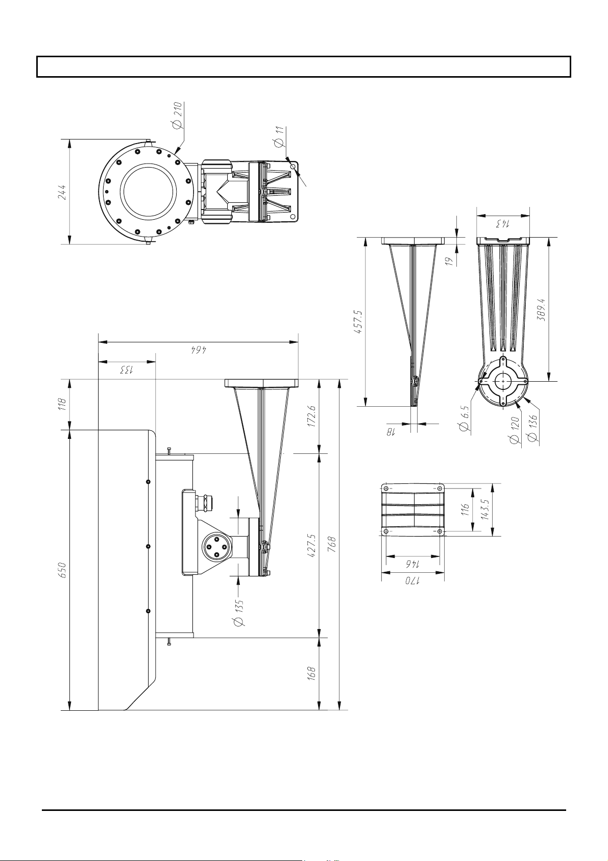
11 Dimensioni Custodia
Pag. 12 MNVCEXH_0702
Page 17
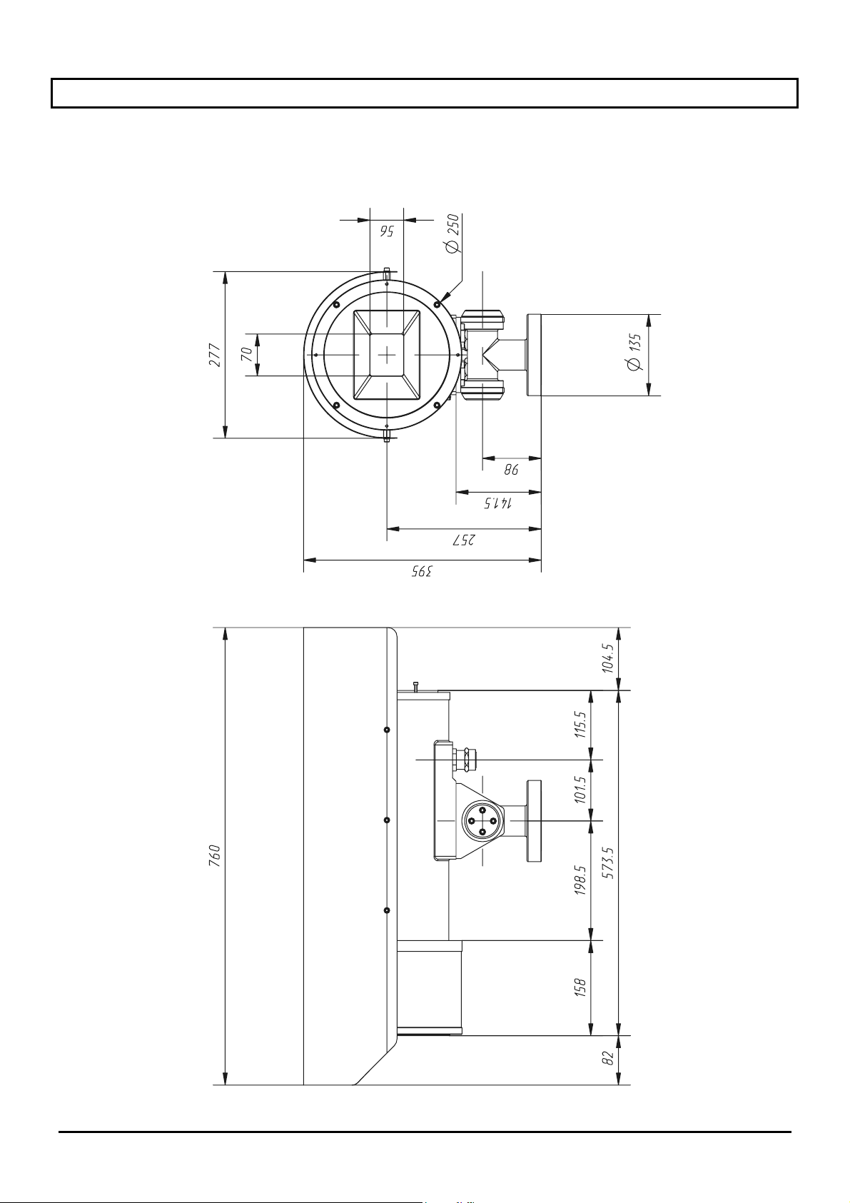
12 Caratteristiche tecniche dispositivo protezione vetro
Dimensioni (Ø x L, mm) Ø 250 x 140
Peso 8 Kg (22.5 Kg con custodia)
Alimentazione 24 Vac
Assorbimento 2 W
Pag. 13 MNVCEXH_0702
Page 18
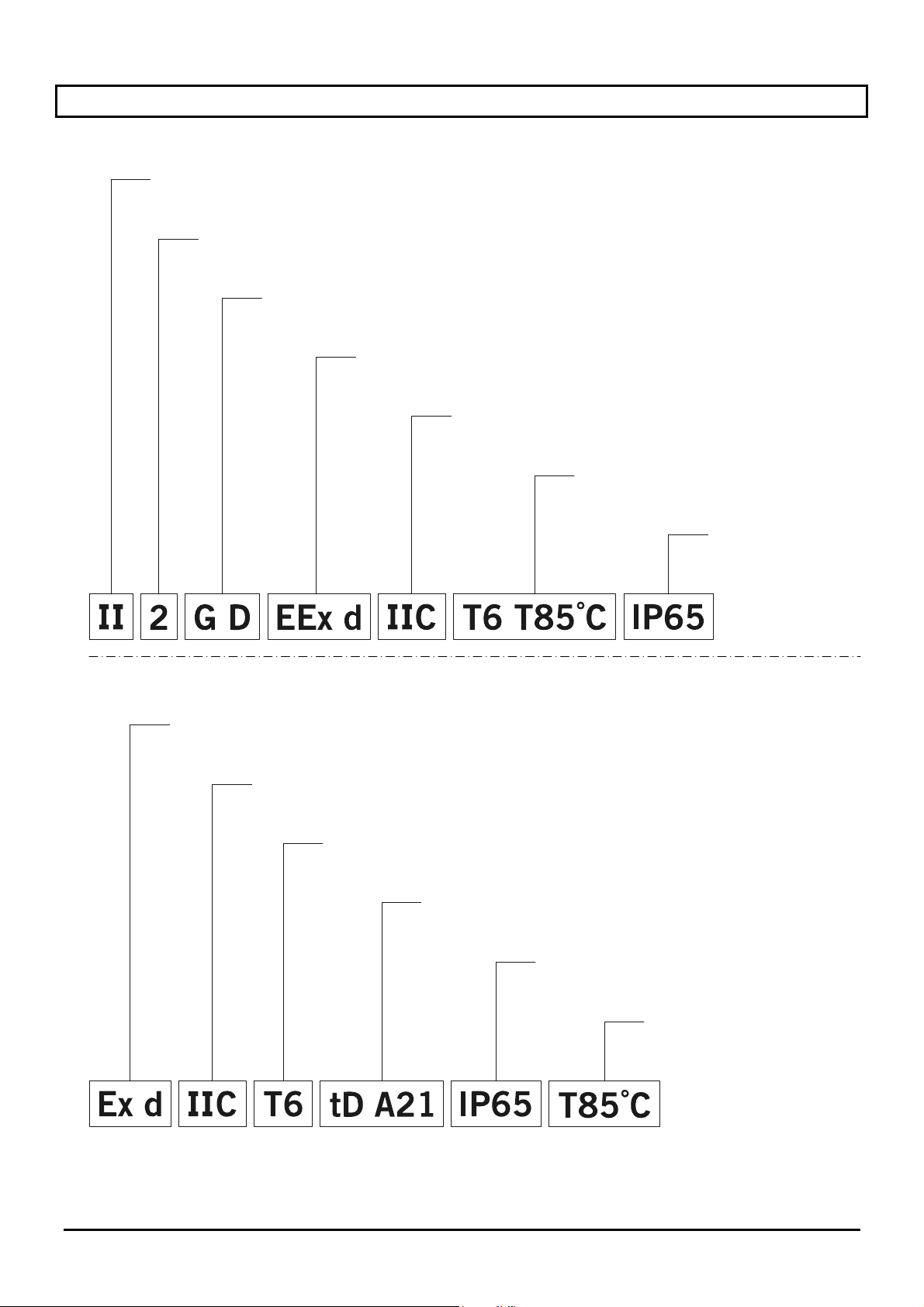
13 Appendice: Codifica antideflagrante
Certificazione ATEX
Gruppo
(apparecchi per superficie, non miniere)
Categoria (grado di protezione elevato, gli apparecchi in questa categoria possono essere
impiegati nella zona 1 e 21 e nella zona 2 e 22)
Tipo atmosfera
(gas e polveri)
Custodia antideflagrante per ambienti
potenzialmente esplosivi
Gruppo
di gas
Classificazione di temperatura
rispettivamente per gas e polveri
Grado di protezione IP
dell’involucro
Certificazione IECEx
Custodia antideflagrante per ambienti
potenzialmente esplosivi
Gruppo
di gas
Classificazione di temperatura
dell’apparecchiatura
Protezione alle polveri infiammabili,
per zone di tipo 21-22
Grado di Protezione
IP dell’involucro
Temperatura massima
superficiale
Pag. 14 MNVCEXH_0702
Page 19
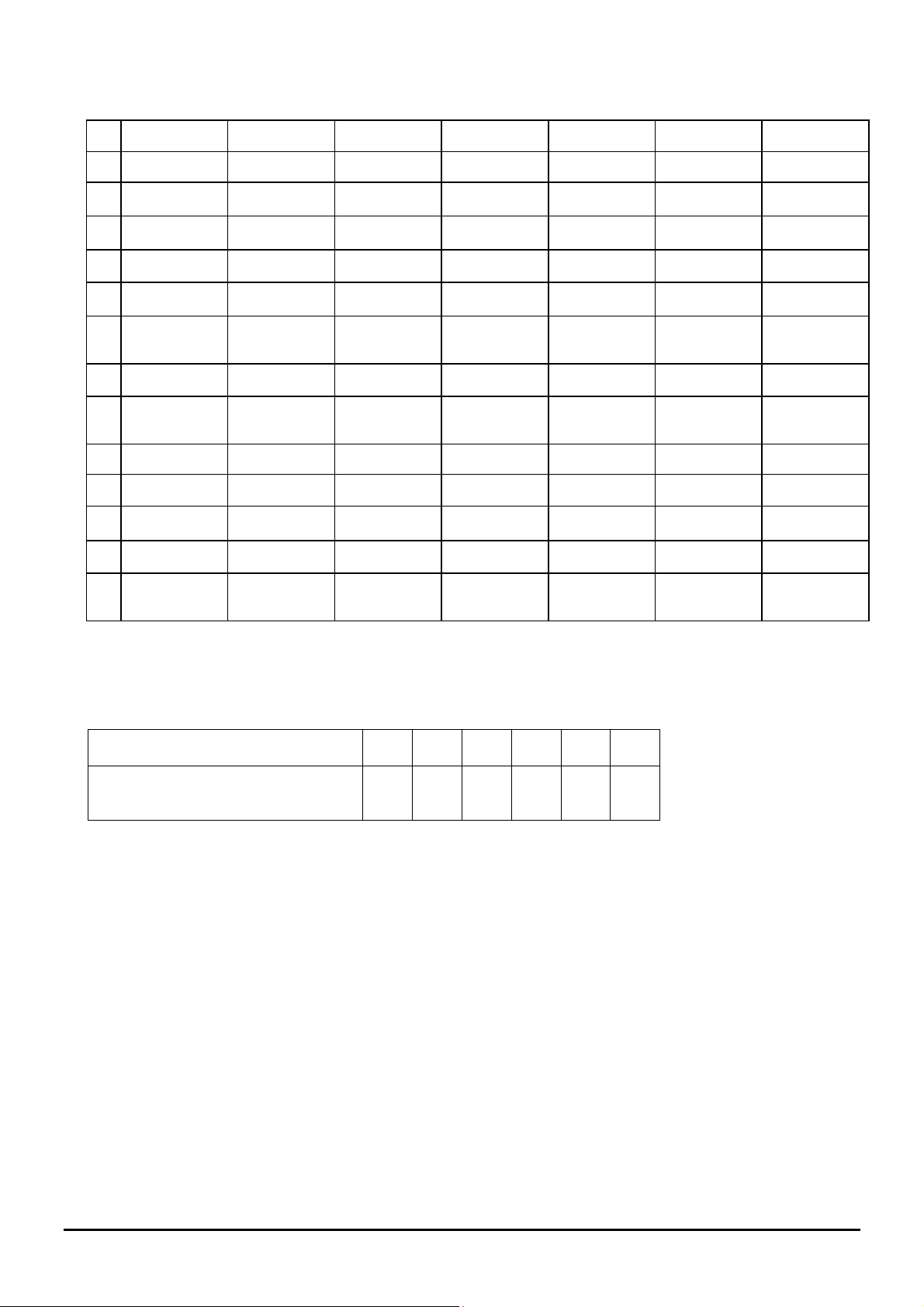
La tabella di seguito mostra la classificazione di alcuni gas e vapori in base ai gruppi di protezione
antideflagrante ed alle temperature.
T1 T2 T3 T4 T5 T6
I Metano (grisù)
IIA Acetone n-butano Benzina Acetaldehyde Nitrato di etile
Etano n-butile Diesel fuel Ethyl ether
Etilacetato Aircraft fuel
Ammoniaca Olio di risc.
Benzene
n-hexane
(puro)
Acido acetico
Monossido di
carbonio
Metanolo
Propano
Toluene
IIB Etilene
IIC Idrogeno Acetilene Solfuro di
carbonio
Note:
La classe di temperatura superiore copre automaticamente le inferiori (T6 è migliore di T1).
La classe IIB copre anche la IIA.
La classe IIC copre anche la IIB e IIA.
Classe di temperatura
T1 T2 T3 T4 T5 T6
Temperatura massima superficiale
450 300 200 135 100 85
(°C) della custodia (*) ammessa dalla
classe corrispondente
(*) Normalmente riferita ad una temperatura ambiente = 50°C. La più bassa temperatura di accensione delle
atmosfere esplosive relative deve essere più elevata della massima temperatura superficiale delle custodie.
Pag. 15 MNVCEXH_0702
Page 20
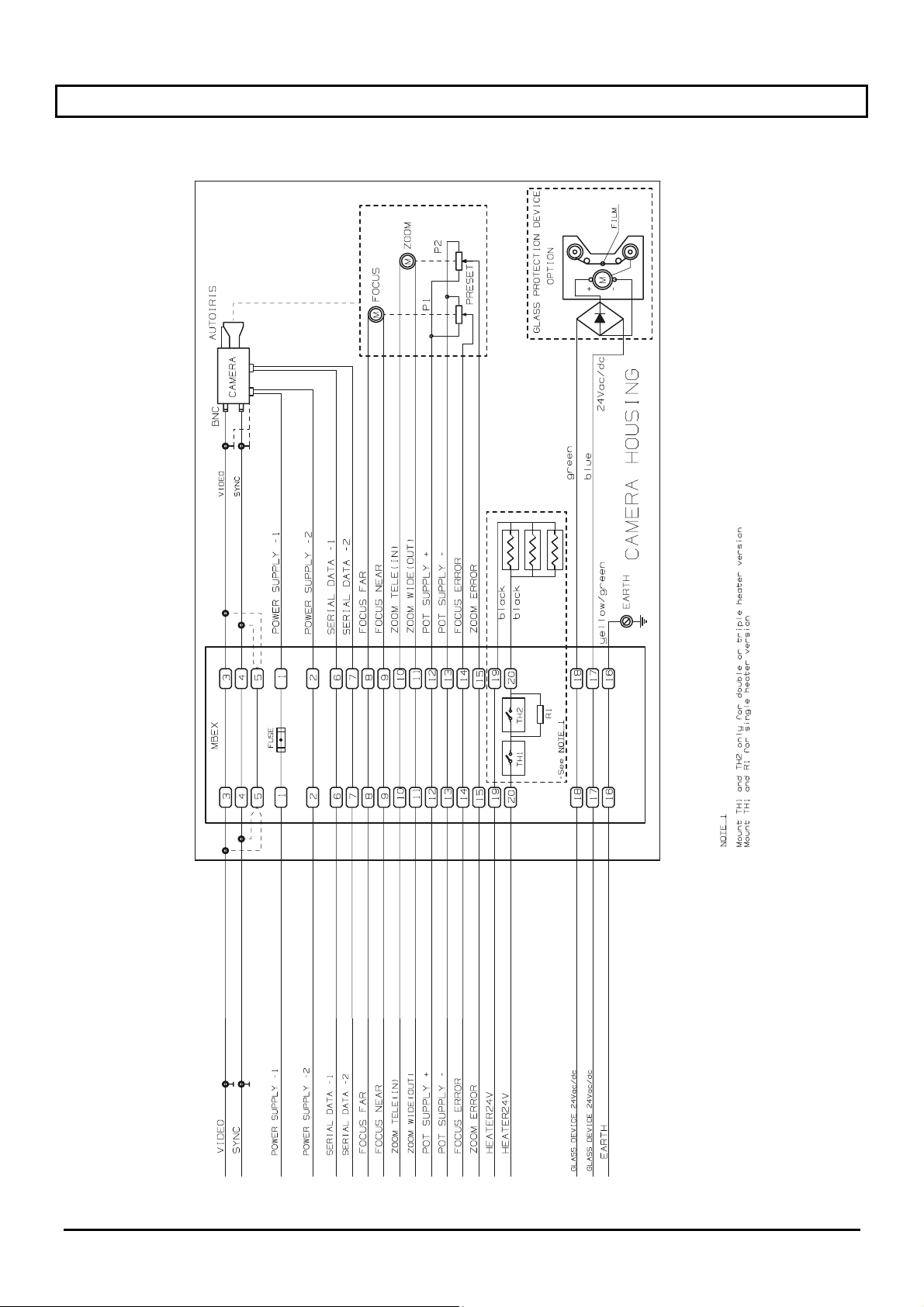
14 Appendice: Schema elettrico
Pag. 16 MNVCEXH_0702
Page 21
OPERATING
INSTRUCTIONS
Page 22

Page 23

INDEX
1 INTRODUCTION .......................................................................................................................................................3
1.1 Packaging contents.............................................................................................................................................3
1.2 Contents of this Manual ......................................................................................................................................3
1.3 Typographic conventions ....................................................................................................................................3
2 SAFETY RULES .......................................................................................................................................................4
3 OPERATING DATA ON THE RATING PLATE........................................................................................................5
4 DESCRIPTION OF HOUSING EXH..........................................................................................................................6
4.1 Glass protection device.......................................................................................................................................6
4.2 Application field ...................................................................................................................................................6
5 INSTALLATION ........................................................................................................................................................7
5.1 Unpacking ...........................................................................................................................................................7
5.2 Control of the operating data on the rating plate ................................................................................................7
5.3 Installation of the camera....................................................................................................................................8
5.4 Housing connection.............................................................................................................................................8
6 STARTING.................................................................................................................................................................9
7 MAINTENANCE ......................................................................................................................................................10
8 TROUBLESHOOTING ............................................................................................................................................11
9 HOUSING TECHNICAL CHARACTERISTICS ......................................................................................................11
10 MAXIMUM SPECIFICATIONS OF THE INSTALLABLE CAMERA WITH LENS ...............................................11
11 HOUSING DIMENSIONS ......................................................................................................................................12
12 GLASS PROTECTION DEVICE TECHNICAL CHARACTERISTICS..................................................................13
13 APPENDIX: EXPLOSION-PROOF CODING .......................................................................................................14
14 APPENDIX: ELECTRIC SCHEMATIC..................................................................................................................16
The manufacturer declines all responsibility for any damage caused by an improper use of the appliances
mentioned in this manual; furthermore, the manufacturer reserves the right to modify its contents without any
prior notice. The documentation contained in this manual has been collected with great care: the manufacturer,
however, cannot take any liability for its use. The same thing can be said for any person or company involved in
the creation and production of this manual.
Page 1 MNVCEXH_0702
Page 24

For information and customer assistance:
HEADQUARTERS ITALY FRANCE
VIDEOTEC S.p.A.
Via Friuli, 6
I-36015 SCHIO (VI) Italy
Tel. +39 0445 697411
Fax +39 0445 697414
[email protected]
www.videotec.com
VIDEOTEC FRANCE S.A.R.L.
Voie du Futur - Zac des Portes
27100 Val de Reuil, France
Tel. +33 2 32094900
Fax +33 2 32094901
[email protected]
www.videotec.com
UK / IRELAND
VIDEOTEC UK SALES
Tel. / Fax +44 (0)1353 775438
[email protected]
www.videotec.com
U.S.A. / CANADA
VIDEOTEC SECURITY, Inc.
The Lower level South Suite
The Ottilio Office Complex I
555 Preakness Ave.
TOTOWA, NJ 07512 - USA
Tel. +1 973 5950788
Fax +1 425 6484289
[email protected]
www.videotec.us
ASIA PACIFIC
VIDEOTEC (HK) Ltd
Unit 2,8/F, Vanta Industrial
Centre
21-33 Tai Lin Pai Road
Kwai Chung, NT, Hong Kong
Tel. +852 2333 0601
Fax +852 2311 0026
[email protected]
www.videotec.com.hk
Page 2 MNVCEXH_0702
Page 25
1 Introduction
1.1 Packaging contents
• 1 explosion-proof housing
• 1 instruction manual
After the delivery, check that the packing is not damaged and shows no evident signs of falls or abrasions.
Should this be so, contact immediately the supplier.
Check that the contents correspond to the above-mentioned list of materials.
1.2 Contents of this Manual
This manual describes EXH series housing, together with their specific procedures of installation, configuration
and use. Read this manual carefully, in particular the chapter concerning the safety rules, before installing
and using the pan & tilt motor.
1.3 Typographic conventions
Different graphic symbols are used in this manual, the meaning of which is here described:
Hazard of electric shock; disconnect the power supply before proceeding, if not otherwise specified.
Hazard of explosion. Read carefully to avoid danger of explosion.
The operation is very important for the correct working of the system: read carefully the procedure
indicated, and carry it out according to the required modalities.
Description of system features: read carefully to understand the following phases.
Page 3 MNVCEXH_0702
Page 26

2 Safety rules
Housing comply with the normative laws in force at the time of editing of this manual, concerning
equipment and protective systems intended for use in potentially explosive atmospheres, electromagnetic
compatibility and general requirements.
Anyway, in order to ensure the users (installer technician and operator), the following warnings are specified for
safety’s sake:
• Please ensure that all equipment is suitable for the application and the environment for which it is intended.
• Please take particular care that the inter-connected equipment is fully compatible with each other and
suitable for such use.
• Check operating temperatures are compatible with device.
• Choose the installation position so that be sufficiently solid to support the weight of the device, also taking
into consideration environmental aspects as particular as exposure to strong wind.
• It is recommended only using brackets or accessories recommended for the installation.
• Ascertain that the device is fixed in solid and reliable way.
• Since the choice of the assembly surface is to care of the user the screws are not supplied for the safe fixing
with the device. It is responsibility of installer using screws suitable for the requested specific purpose.
• The installation and the maintenance of the device (and the whole plant of which it does part) must be made
by technical staff adequately qualified and work according to the national rules for the safety of the staff.
• Use appropriate tools. Some specific utensils can be required, for installation reasons, in relation to the
place in which the device is installed.
• Make sure that the installation satisfies the local specifications.
• This device must be installed outside the range of the user or whoever is able to come in to accidentally
contact.
• Connect the unit to a power supply corresponding to the one indicated on the rating plate (see next section
Operating data on the rating plate)
• Before moving or carrying out technical operations on the unit, disconnect it from mains.
• The unit must be opened only by skilled technical personnel in a non explosive atmosphere. The warranty
limits does not cover damages resulting from an improper use of the unit.
• Do not allow children or unskilled persons to use the unit.
• The unit is considered off-line only when the power supply is disconnected and the cables aimed to connect
the unit with other devices have been removed.
• Before the power-supply a protection device must be installed in the electrical installation of the building.
• We recommend is to the user not install inside the any device equipment than dangerous radiation kinds.
• For the after-sales service, please contact exclusively the authorised technical personnel.
• Keep the present manual with care for any future consultation.
This device must be connected to the ground!
Page 4 MNVCEXH_0702
Page 27
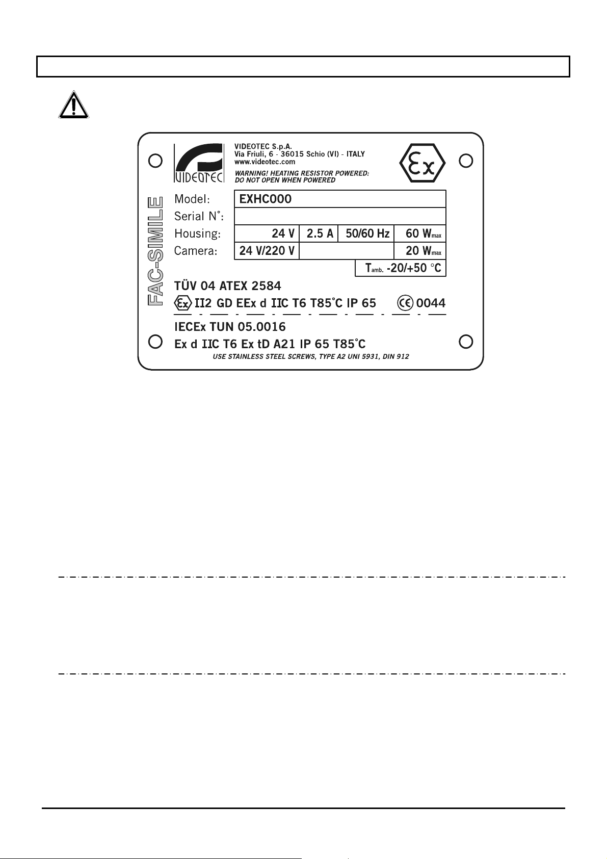
3 Operating data on the rating plate
On housing series EXH rating plate has following information:
• Symbol
• Manufacturer name and address
• Model identification code
• Serial number
• Housing:
• Power supply (V)
• Rate current (A)
• Frequency (Hz)
• Power consumption (W)
• Camera:
• Power supply (V)
• Power consumption max (W) – (the camera data refer to the tension and the max. consumption
• Operating temperature referring to the identification code of the model
• ATEX certificate number
• Zone type classification, protection process and temperature rating for those this product is allowed
to operate according to the ATEX standard
• IP protection degree
• CE marking
• Notify body number releasing the ATEX certificate
• IECEx certificate number
• Zone type classification, protection process and temperature rating for those this product is allowed
to operate according to the IECEx standard
Before installing make sure that its supply features correspond to those requested. The use of unsuitable
appliances can cause serious damage to the personnel and the system
b
features allowed for its operation)
Page 5 MNVCEXH_0702
Page 28

4 Description of housing EXH
The explosion proof housing EXH series have been designed to be used with cameras working in industrial
areas with explosive environments like gas, vapours, fogs or mixed air and powders.
The EXH housings, are made with strong Anticorodal aluminium die-cast alloy of AlSi7Mg EN AC-42000 group
and their chemical composition is defined in the UNI EN 1706 standard.
Depending on the model, all external components are stove enamelled using powder or treated with special
coatings offering an excellent resistance to UV rays, salt-spray, environment polluting substances.
They are constructed according to the 94/9/CE ATEX standard and IEC 60079-0:2000, IEC 60079-0:2001, IEC
61241-1:2004 protocols.
The camera housing consists of a cylindrical tube, fitted with a flange which incorporates a rugged and
transparent glass; on the opposite side it is installed an other flange for closing the tube and supporting the
camera fixing board. The weatherproof standard IP65 is ensured also by two 3/4" cable glands for service
cables of a diameter ranging from 14 mm to 17 mm.
The thermal imaging camera housings, detecting the heat emission, require a special filter on the front part of
the housing. Its structure, mainly composed by Germanium, guarantees the same resistance and security
features as well as the standard glass.
This housing model is built according the 94/9/CE Atex standard.
The unit can be also supplied with the following additional accessories:
• sunshield (EXHS);
• mounting bracket with articulation support (EXWBJ) for wall installation;
4.1 Glass protection device
The housing series EXH can be equipped with the glass protection device, installed on the front opening of the
camera housing. It consists of a connection flange with the housing, a closing flange and an explosion-proof
central body containing a rugged and transparent glass, a direct current motor power supplied at 24 Vdc, two
windings and a transparent Mylar film, installed just in front of the glass. The motor drives, through four pinions
with gear rim, the winding for recovering the dirty Mylar film, while at the same time the other winding installed
on the opposite side releases the clean film. The motor is remotely controlled through a two wires on-off contact
(common and + 24Vdc).
The control unit of the glass protection device is provided by the customer!
The transparent Mylar film allows to obtain about 350 shifting steps. When the film is dirty, the operator will
activate the motor shifting the film until to obtain a clean camera picture (the step for allowing the completely
shift of the dirty film is about 50 cm). The end of the Mylar film will directly indicated to the operator, through
suitable marks printed on the last 50 cm of the film.
If requested, the film shifting could be also automatically time-controlled, through a suitable control system (not
included in the supply).
To replace the Mylar film, take out the windings and replace the dirty film with a clean one.
4.2 Application field
The use of housing EXH is in fixed position for the vigilance, by camera installed by the user inside, of
zones with atmosphere explosive classified 1-21 or 2-22.
• The EXH housing s constructed and certificated in compliance to the 94/9/CE ATEX standard and the IEC
60079-0:2000, IEC 60079-0:2001, IEC 61241-1:2004 protocols which define the range of application and the
minimum safety requirements.
Page 6 MNVCEXH_0702
Page 29
5 Installation
The unit must be installed exclusively by skilled technical personnel.
Make connections and tests in laboratory before the installation in the site.
Use adequate tools.
The following procedures are to be made at disconnect unit, if not differently shown.
An adequate protection device must be installed in the electric plant before the device.
Do not exceed the specified performances.
Do not replace the screws of the housing with others of different type.
Execute all the connections in not explosive atmosphere.
5.1 Unpacking
If the packaging does not present evident faults (due to falls or anomalous scratches), make sure that its
contents correspond to the list of items contained in paragraph Packaging contents, in section Introduction.
The container is completely made of recyclable material. The installer will take care to dispose it according to
the recycling programs or, in any case, according to the rules in force in the country of destination.
5.2 Control of the operating data on the rating plate
Before installing the unit, control if the goods supplied correspond to the required specifications by
examining the rating plates, according to the section Operating data on the rating plate
Never make alterations or connections not provided for in the present manual: the use of unsuitable devices
can lead to serious risks for the safety of the personnel and the security of the plant.
.
Page 7 MNVCEXH_0702
Page 30
5.3 Installation of the camera
Not to use devices exceed from the specifications!
Not to use devices which produce dangerous radiations!
The rear flange of the camera housing fitted with 12 screws M6 thread. Besides it is fitted with 3 screws, located
at 120° each other for facilitating the flange extraction. In fact, after having screwed off the screws with M6
thread, it is necessary to screw on the 3 screws with M4 thread (one turn at a time, in rotation) for easily
extracting the flange.
For installing the camera it is necessary to extract the closing flange of the housing, to which it is connected the
camera fixing board with relevant terminal strip. This board is supported by two guides fixed to the housing; if
the closing flange is extracted, the board slides on the guides, so making very easy the installation and relevant
connection of the camera and its accessories. It is recommended to insulate the camera from its relevant
supporting board, using the suitable insulated separators included in the supply.
For installing the housing can be used the suitable articulation, provided with 4 M6 holes and located at 90°
each other, the suitable bracket, for wall mounting, to be installed through the 4 M8 holes.
(For particular indication refer to the following picture and the schematic in appendix)
Close the flange correctly after the installation of the camera. Screwing up the12 screws with 12.5 Nm torque.
Closing flange
Terminal connection
Camera support plate
5.4 Housing connection
Attention: before making the following operations make sure that the line voltage of the housing is
correct.
For connection the housing to the control unity use the multi-core cable provided to outfit, refer to the electric
scheme in appendix and execute the following operations:
• connect cables to the housing through cable glands;
• make connections with the camera and lens;
• power to the unit;
• execute working tests.
Page 8 MNVCEXH_0702
Page 31
6 Starting
Before executing the starting, installer:
• have carefully and completely read the manual use present;
• have installed the camera and lens correctly;
• have checked the working of the system with positive result;
• have arranged a suitable power line.
Please take note following security prescriptions:
• Because the system is heavy, an adequate system is necessary of transport and handling;
• Make sure to have disconnected the power before executing any operation;
• Install a protection device before the line of the device in the electric plant of the building.
• Be sure that there are all the security prescriptions concern the staff's safety;
• The electric installation of the plant must be corresponding to the current local rules.
Please take note following explosion prevention prescriptions;
• Choose a solid and stable support surface;
• Choose an suitable support bracket, if used;
• Use suitable tools to the zone one works in;
• Do not open the housing or the command unity if there is the possibility potentially of presence of explosive
atmosphere;
• Use safe and lasting screws or other fixing systems.
The unit must be connected to a suitable connection of electric earth!
After the starting stored this instruction manual for future consultations.
Page 9 MNVCEXH_0702
Page 32
7 Maintenance
The housing series EXH does not require special maintenance operations.
In anyway the maintenance can be:
Ordinary (periodically):
• Glass cleaning: must be to do with water or other clean liquid that do not make dangers situation;
• Device cleaning
surface. The maintenance frequency operations depends on the kind of environment where the housing is
installed;
• Cables control:
case it is necessary to execute an extraordinary maintenance;
• Replacement tape in Mylar
suitable security conditions in the Starting. It is necessary to unscrew the four screws of fixing of the lid of the
glass protection and to replace the windings with the dirty tape with those with the clean tape with a simple
slip off.
Extraordinary (in particular situations):
• Replacement of the frontal group equipped with glass (or glass protection device in the versions where
foreseen);
• Replacement of the internal support plate with wiring for heater and terminal connection board, with the
opportune replacement in the versions with or without the glass protection device;
• Replacement cable glands;
• Usury and dangerous deterioration of the cables;
• Not working of the camera or lens;
• Deflagration inside or close to the housing;
• Any other circumstance which involves the opening the housing.
One advises, for all these cases the system must be taken back in laboratory to make the necessary
operations.
: must be performed periodically to avoid the excessive amount of powder on the external
that it must not present such usury or deterioration signs to create danger situations, in this
(glass protection device version): that it must be executed in the minimum
In case of damage the replacement or repair of other interested part interested besides the
suitable ones, it must be executed by manufacturer!
Any replacement of the particulars show must be executed only using VIDEOTEC original
replacements scrupulously following the maintenance instructions enclosed with every replacement kit.
The manufacturer declines all responsibility for any damage caused by tampering, use of not
original replacements, installations and maintenance/repairs carried out by not prepared staff, of all the
equipment mentioned in this manual.
Page 10 MNVCEXH_0702
Page 33
8 Troubleshooting
Although the housing series EXH is characterised by a great ease of use, sometimes troubles may
occur, especially during the installation and configuration phases or using the unit.
PROBLEM PROBABLE CAUSE REMEDY
Camera do not turn on
Camera turn on bat no video
signal
Lens do not work
Heater do not work
Image from camera do not
correct
• No power supply
• Fuse blown
• Incorrect connection • Check connection cable
• Lens power supply is not correct
or missing
• Thermostat do not set
• Incorrect connection
• Lens set not correct
• Camera working not properly
• Check the power cable
• Replace fuse
• Check lens power supply
• Check thermostat temperature
• Check connection cable
• Check lens set
• Replace the camera
9 Housing technical characteristics
Inside housing dimensions
(Ø x L, mm)
Housing weight 14.5 kg (22.5 kg with glass protection device)
Swivel weight 3.5 kg
Protection degree IP 65
Execution II 2 GD EExd IIC T6 T85°C IP 65 ATEX
Operating temperature
Power supply 24/240 Vac, 50/60 Hz
Consumption 20/40/60 W (heater housing)
Ø 180 x 380 (460 with glass protection device)
Ex d IIC T6 Ex tD A21 T85°C IP 65 IECEx
-20°C ÷ + 50°C
-40°C ÷ + 50°C (Only for reinforced heater versions)
10 Maximum specifications of the installable camera with lens
Camera useful area (L x H x P, mm) 100 x 100 x 280 (360 with glass protection device)
Max power 20W
Max voltage 240V
Attention: the housing power supply must be the same used for
the heater system
Page 11 MNVCEXH_0702
Page 34
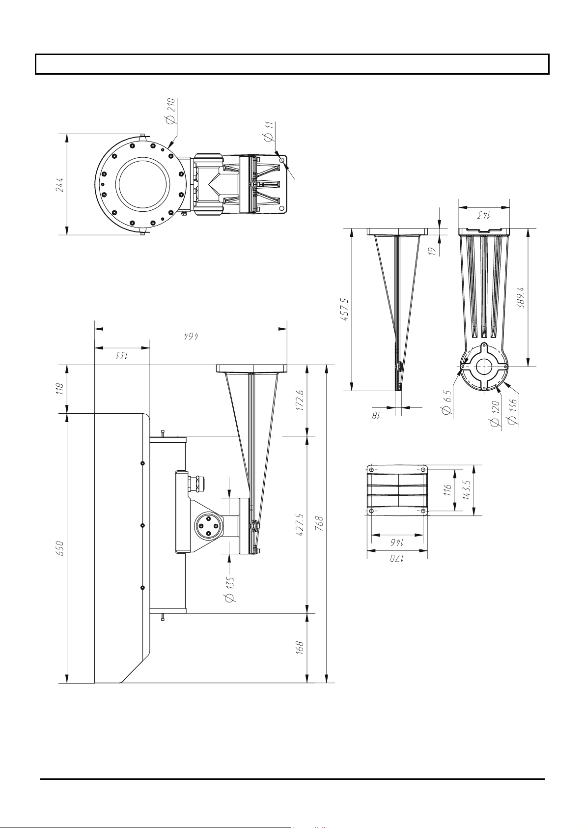
11 Housing dimensions
Page 12 MNVCEXH_0702
Page 35
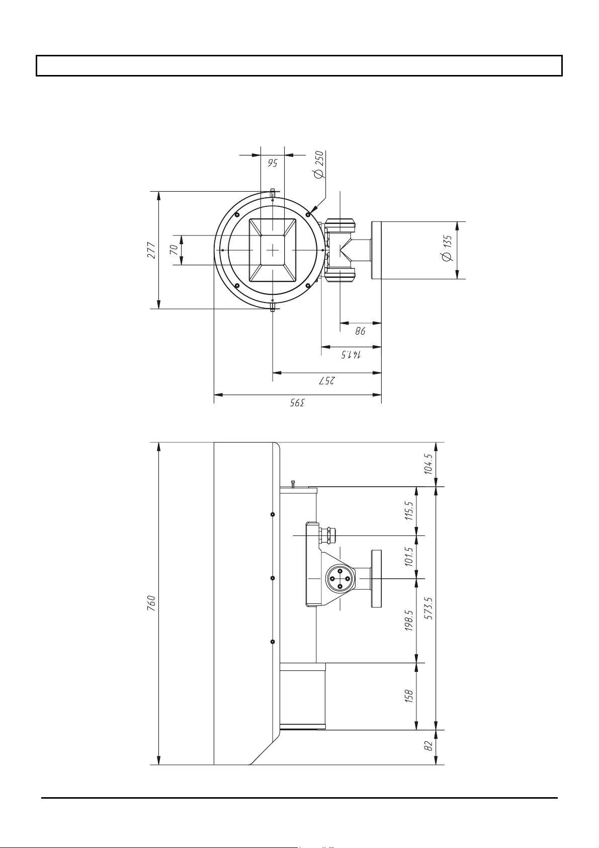
12 Glass protection device technical characteristics
Dimensions (Ø x L, mm) Ø 250 x 140
Weight 8 Kg (22.5 Kg with housing)
Power 24 Vac
Consumption 2 W
Page 13 MNVCEXH_0702
Page 36
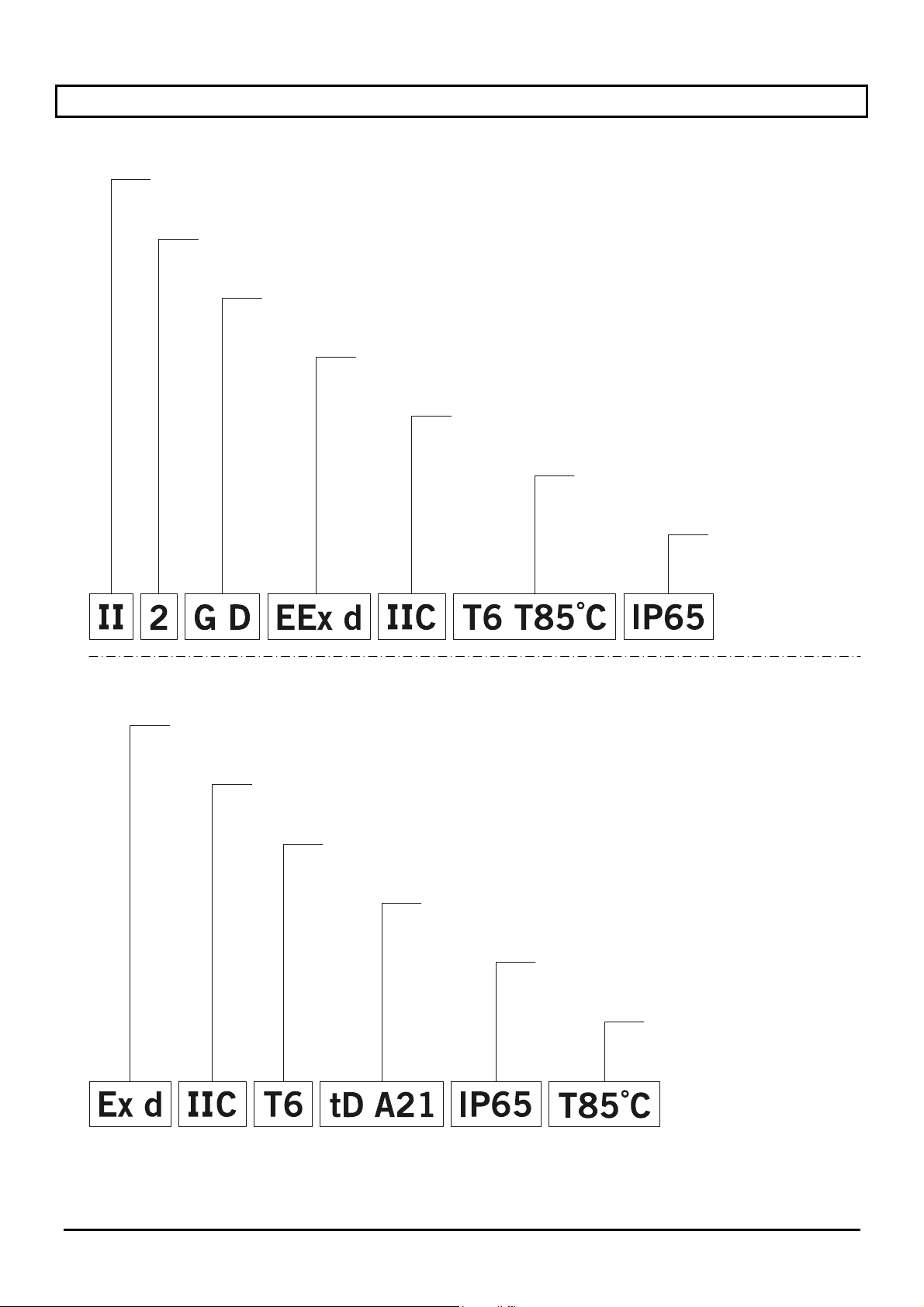
13 Appendix: Explosion-proof coding
ATEX Certification
Group
(surface device, no mining)
Category (elevated protection degree, the devices of this category can be installed in zone 1
and 21 and in zone 2 and 22)
Atmosphere type
(gases and dusts)
Explosionproof housing for
potentially explosive areas
Gases
group
Temperature classification
for gases and dusts respectively
Enclosure weatherproof
IP standard
IECEx Certification
Explosionproof housing for
potentially explosive areas
Gases
group
Device class
temperature
Dust ignition protection,
zones type 21-22
Enclosure weatherproof
IP standard
Max superficial
temperature
Page 14 MNVCEXH_0702
Page 37

The following table shows the classification of a some gases and steams on the basis of the groups of
explosion-proof protection and to the temperatures.
T1 T2 T3 T4 T5 T6
I Methane
IIA Acetone n-butane Benzine Acetaldehyde Ethyl nitrate
Ethane n-butyl Diesel fuel Ethyl ether
Ethyl acetate Aircraft fuel
Ammonia Heating Oil
Benzene
n-hexane
(pure)
Acetic acid
Carbon
monoxide
Methanol
Propane
Toluene
IIB Ethylene
IIC Hydrogen
Acetylene Carbon
disulphide
Note:
The class of superior temperature automatically covers the lower ones (T6 is better than T1).
The IIB class also covers the IIA.
The IIC class also covers the IIB and IIA.
Temperature class
T1 T2 T3 T4 T5 T6
Maximum superficial temperature (°)
450 300 200 135 100 85
of the housing (*) admitted by the
relative class
(*) Normally reported to an temperature environment = 50°C. The lowest temperature of ignition of the relative
explosive atmospheres must be higher than the maximum superficial temperature of the housings.
Page 15 MNVCEXH_0702
Page 38
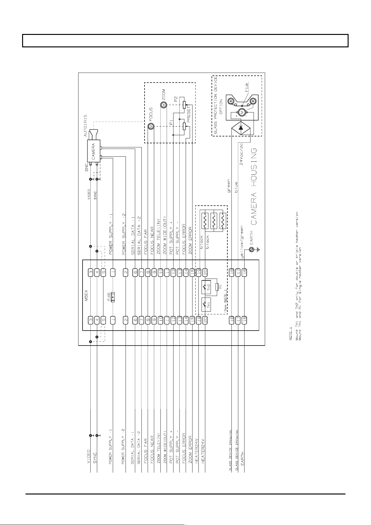
14 Appendix: Electric schematic
Page 16 MNVCEXH_0702
Page 39
MANUEL
D’INSTRUCTIONS
Page 40

Page 41

INDEX
1 INTRODUCTION .......................................................................................................................................................3
1.1 Contenu de l'emballage ......................................................................................................................................3
1.2 Contenu du manuel.............................................................................................................................................3
1.3 Conventions typographiques ..............................................................................................................................3
2 NORMES DE SECURITE..........................................................................................................................................4
3 DONNEES DE MARQUAGE ....................................................................................................................................5
4 DESCRIPTION DU CAISSON EXH ..........................................................................................................................6
4.1 Dispositif de protection du verre .........................................................................................................................6
4.2 Gamme d'utilisation.............................................................................................................................................6
5 INSTALLATION ........................................................................................................................................................7
5.1 Ouverture de l'emballage ....................................................................................................................................7
5.2 Contrôle marquage .............................................................................................................................................7
5.3 Installation de la caméra .....................................................................................................................................8
5.4 Connexion du caisson.........................................................................................................................................8
6 MISE EN SERVICE ...................................................................................................................................................9
7 ENTRETIEN.............................................................................................................................................................10
8 RESOLUTION DES PROBLEMES.........................................................................................................................11
9 CARACTERISTIQUES TECHNIQUES CAISSON .................................................................................................11
10 VALEURS MAXIMALES DES CAMERAS ET PARTIES OPTIQUES POUVANT ETRE INSTALLEES .................11
11 DIMENSIONS CAISSON.......................................................................................................................................12
12 CARACTERISTIQUES TECHNIQUES DU DISPOSITIF DE PROTECTION DU VERRE...................................13
13 ANNEXE: CODIFICATION ANTIDEFLAGRANTE...............................................................................................14
14 ANNEXE: SCHEMA ELECTRIQUE......................................................................................................................16
Le fabricant décline toute responsabilité en cas de dommages dus à une utilisation incorrecte des appareils
décrits dans ce manuel, et se réserve le droit d'en modifier le contenu sans préavis. La documentation de ce
manuel a été sélectionnée et contrôlée avec une extrême attention ; le fabricant décline néanmoins toute
responsabilité concernant l'utilisation de cette documentation, ainsi qu'au sujet des personnes ou sociétés
ayant participé à la conception et à la réalisation de ce manuel.
Page 1 MNVCEXH_0702
Page 42

Pour toute information et demande d'assistance:
HEADQUARTERS ITALY FRANCE
VIDEOTEC S.p.A.
Via Friuli, 6
I-36015 SCHIO (VI) Italy
Tel. +39 0445 697411
Fax +39 0445 697414
[email protected]
www.videotec.com
VIDEOTEC FRANCE S.A.R.L.
Voie du Futur - Zac des Portes
27100 Val de Reuil, France
Tel. +33 2 32094900
Fax +33 2 32094901
[email protected]
www.videotec.com
UK / IRELAND
VIDEOTEC UK SALES
Tel. / Fax +44 (0)1353 775438
[email protected]
www.videotec.com
U.S.A. / CANADA
VIDEOTEC SECURITY, Inc.
The Lower level South Suite
The Ottilio Office Complex I
555 Preakness Ave.
TOTOWA, NJ 07512 - USA
Tel. +1 973 5950788
Fax +1 425 6484289
[email protected]
www.videotec.us
ASIA PACIFIC
VIDEOTEC (HK) Ltd
Unit 2,8/F, Vanta Industrial
Centre
21-33 Tai Lin Pai Road
Kwai Chung, NT, Hong Kong
Tel. +852 2333 0601
Fax +852 2311 0026
[email protected]
www.videotec.com.hk
Page 2 MNVCEXH_0702
Page 43
1 Introduction
1.1 Contenu de l'emballage
• 1 caisson antidéflagrant;
• 1 manuel d'utilisation.
Lors de la livraison du produit, contrôler que l'emballage est intact et ne porte aucun signe de chute ni éraflure.
Si l'emballage est endommagé, contacter immédiatement le fournisseur.
Contrôler que le contenu correspond à la liste matériel indiquée plus haut.
1.2 Contenu du manuel
Ce manuel contient la description des caissons de la série EXH et des opérations nécessaires à leur
installation, configuration et utilisation. Il est indispensable de
chapitre concernant les normes de sécurité
, avant de procéder à l'installation et à l'utilisation du récepteur.
lire ce manuel avec attention, et en particulier le
1.3 Conventions typographiques
À l'intérieur de ce manuel sont utilisés différents symboles graphiques, dont la signification est indiquée ci-dessous:
Risque de choc électrique; sauf indication contraire expresse, couper l'alimentation avant de procéder
aux opérations prévues.
Danger d'explosion. Lire avec attention pour éviter tout risque d'explosion.
Cette opération est essentielle au fonctionnement correct du système. Il est conseillé de lire avec
attention la description des opérations et de se conformer aux indications données.
Description des caractéristiques du système: il est conseillé de procéder à une lecture attentive pour
une meilleure compréhension des phases suivantes.
Page 3 MNVCEXH_0702
Page 44

2 Normes de sécurité
Le caisson est conforme aux normes en vigueur lors de la publication de ce manuel en ce qui concerne
les appareils et systèmes de protection destinés à une utilisation en atmosphères potentiellement dangereuses,
la compatibilité électromagnétique et les conditions générales nécessaires.
Il est toutefois nécessaire de donner aux utilisateurs (techniciens installateurs et opérateurs) plusieurs
indications leur permettant d'opérer dans des conditions de sécurité maximales:
• Contrôler que tous les dispositifs sont adaptés à l'environnement et à l'application pour lesquels ils sont
projetés.
• Contrôler que les dispositifs connectés sont entièrement compatibles et adaptés à l'utilisation prévue.
• Contrôler que les températures d'exploitation sont compatibles avec les dispositifs.
• S'assurer d'installer les dispositifs afin de garantir la sécurité de l'installation et du personnel chargé de la
mise en service.
• Choisir un lieu d'installation suffisamment robuste pour supporter le poids du dispositif en tenant également
compte des aspects particuliers de l'atmosphère ambiante, comme par ex. une exposition à un vent fort.
• Il est conseillé d'utiliser exclusivement les brides ou accessoires conseillés pour l'installation.
• Contrôler que le dispositif est fixé de façon solide et fiable.
• Le choix de la surface de montage relevant de la responsabilité de l'utilisateur, aucune vis n'est fournie pour la
fixation du dispositif sur la surface choisie. L'installateur doit utiliser des vis adaptées à l'application prévue.
• L’installation et l'entretien de l'appareil (et de la totalité de l'installation dont il fait partie) doivent être
effectués par un personnel technique qualifié et conformément aux normes nationales pour la sécurité du
personnel.
• Utiliser des outils adéquats. Des instruments spécifiques peuvent être nécessaires pour l'installation en
fonction du lieu de cette dernière.
• S'assurer que l'installation est conforme aux spécifications locales.
• Ce dispositif doit être installé hors de portée de l'usager ou de quiconque risquant d'entrer en contact
accidentel avec l'appareil.
• Connecter le système à une ligne d'alimentation correspondant aux indications des étiquettes de marquage
(voir chapitre suivant Données de marquage).
• Débrancher la fiche d'alimentation avant tout déplacement ou intervention technique sur l'appareil.
• L'appareil ne doit être ouvert que par un personnel technique qualifié et en atmosphère non explosive. Toute
manipulation de l'appareil entraînera l'annulation de la garantie.
• Ne pas laisser l'appareil à portée des enfants ou de personnes incapables.
• L'appareil ne peut être considéré comme désactivé que si l'alimentation est coupée et les câbles de
connexion aux autres dispositifs déconnectés.
• Avant d'alimenter le dispositif, installer un dispositif de protection de l'installation électrique de l'édifice.
• Il est conseillé de n'installer aucun appareil produisant des radiations dangereuses à l'intérieur du dispositif.
• Pour toute assistance technique, s'adresser exclusivement au personnel technique autorisé.
• Conserver ce manuel avec soin pour toute nécessité de consultation.
Ce dispositif doit être branché à la terre!
Page 4 MNVCEXH_0702
Page 45
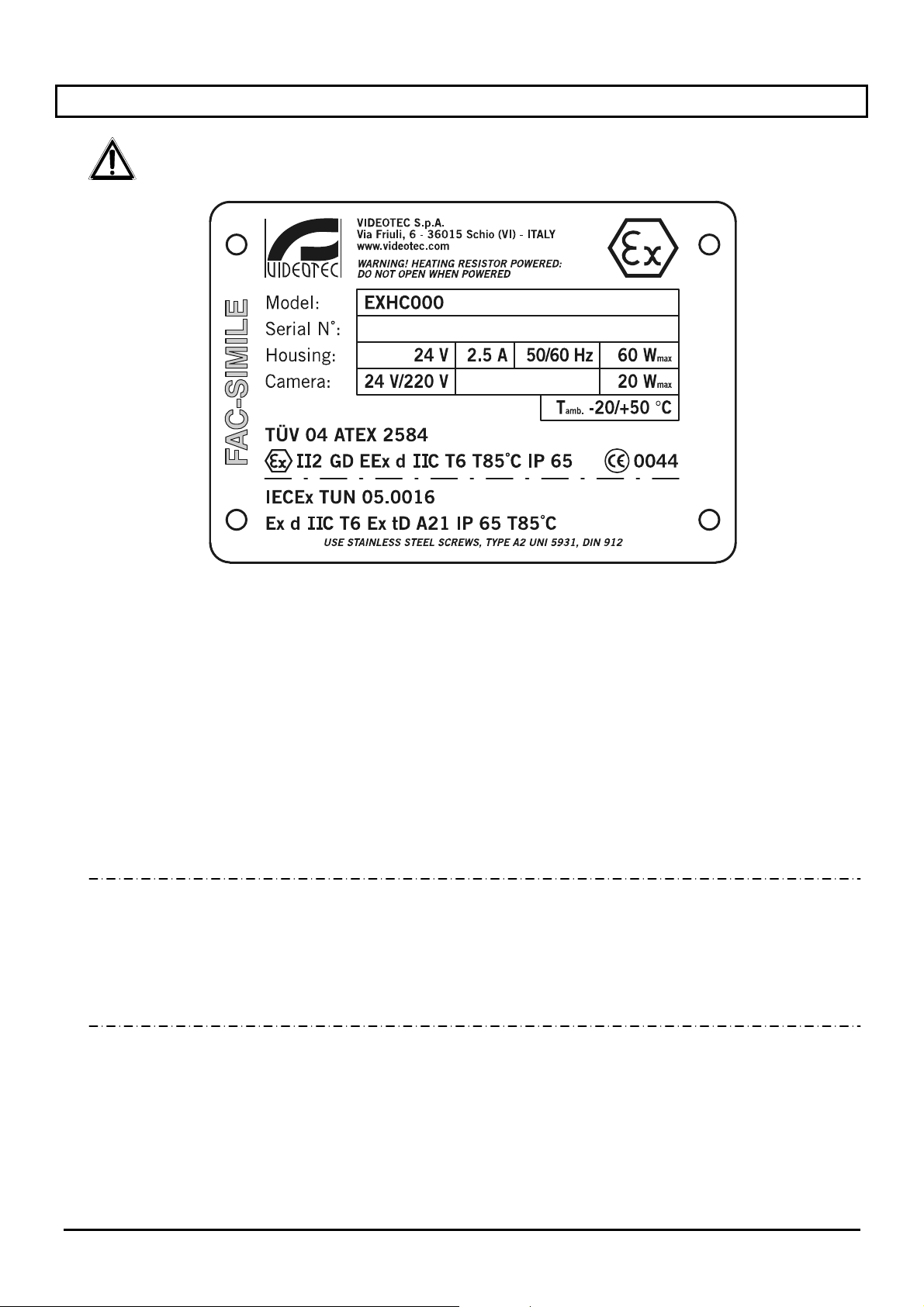
3 Données de marquage
Sur le caisson série EXH figurent les informations suivantes:
• Symbole
• Nom et adresse du constructeur
• Code d’identification du modèle
• Numéro de série
• Caisson:
• Tension d'alimentation (V)
• Courant absorbé (A)
• Fréquence (Hz)
• Consommation caisson (W)
• Caméra:
• Tension d'alimentation (V)
• Consommation maximum (W) – (les données pour la caméra se réfèrrent aux caractéristiques de la
• Temperature ambiante d’exercice reférante au code d’identification du modèle
• Numéro du certificat ATEX
• Classification du type de zone, type de protection et classe de température pour laquelle est
possible l’utilisation de ce produit selon la directive ATEX.
• Degré de protection IP
• Marquage CE
• Numéro de l'organisme notifié qui a relâchè le certificat ATEX
• Numéro du certificat IECEx
• Classification du type de zone, type de protection et classe de température pour laquelle est
possible l’utilisation de ce produit selon la directive IECEx
Lors de l'installation, contrôler que les caractéristiques d'alimentation et de protection du dispositif
correspondent aux caractéristiques nécessaires. L'utilisation d'appareils non adéquats peut comporter des
risques graves pour le matériel et pour la sécurité du personnel.
b
tension et de la consommation max. pour son fonctionnement).
Page 5 MNVCEXH_0702
Page 46

4 Description du caisson EXH
Le caisson antidéflagrant de la série EXH a été conçu pour l'utilisation de caméras installées en environnement
industriel comportant la possibilité d'atmosphères explosives dues à des gaz, vapeurs, brouillards ou mélanges
d'air ou de poudres.
Les caissons EXH sont réalisés en fusion massive d'alliage d'aluminium Anticorodal du groupe AlSi7Mg EN
AC-42000 dont sa composition chimique est définie par la norme UNI EN 1706.
Selon le modèle, tous les elements sont vernis en utilisant des poudres au four ou traités par des revêtements
paticuliers qui offrent une excellente résistence contre les rayons ultraviolets, les brumes salines et les agents
polluants présents dans l’atmosphère.
Ils sont réalisés selon la directive 94/9/CE ATEX et les protocoles IEC 60079-0:2000, IEC 60079-0:2001, IEC
61241-1:2004.
Le corps de la caméra se compose d'un tube cylindrique muni d'une bride logeant un verre transparent robuste;
sur la partie opposée au verre est prévue une seconde bride qui, outre fermer le cylindre, soutient la plaque
pour la fixation de la caméra. Le degré de protection IP65 est également garanti par deux presse-câbles 3/4”
GAZ pour l'introduction des câbles de service avec une diamètre de 14 mm a 17 mm.
L’utilisation de caméras thermiques en mesure de détecter les émissions de chaleur nécessite l’utilisation d’un
filtre spécial sur la partie frontale du caisson. Sa structure, constituée essentiellement de germanium, offre les
caractéristiques de résistance et de sécurité du verre standard.
Cette version de caisson est construit conformément aux prescriptions de la directive 94/9/CE Atex.
Le caisson peut également être équipé des accessoires suivants:
• toit pare-soleil (EXHS);
• bride articulée pour fixation murale (EXWBJ);
4.1 Dispositif de protection du verre
Les caissons antidéflagrants de la série EXH peuvent être équipés du dispositif de protection du verre installé
sur l'ouverture frontale du caisson. Ce dispositif comprend une bride de raccord avec le caisson, une bride de
fermeture, et une unité centrale antidéflagrante contenant un verre transparent robuste, un moteur à courant
continu alternatif alimenté à 24VCC, deux bobineurs et une pellicule transparente en mylar installée devant le
verre. Au moyen de 4 pignons coniques dentés, le moteur pilote un bobineur pour la récupération de la pellicule
sale, tandis que l'autre bobineur distribue la pellicule propre. Le moteur est contrôlé à distance au moyen d'un
contact ON-OFF à deux fils (le premier de type courant et le second + 24VCC).
L'unité de contrôle du dispositif de protection du verre est fournie par le client!
La pellicule transparente en mylar permet environ 350 pas d'avancement. En effet, lorsque la pellicule est sale,
l'opérateur actionne le moteur qui fait avancer la pellicule jusqu'à obtenir une image nette (le pas permettant le
défilement complet du film sale est d'environ 50 mm). La fin de la bande est directement signalée à l'opérateur
au moyen de marques imprimées sur les 50 derniers centimètres de pellicule.
L'avancement de la pellicule peut également s'effectuer automatiquement de façon temporisée au moyen d'un
système de contrôle adéquat (non fourni).
Pour remplacer la pellicule, ouvrir la bride frontale et retirer les bobineurs. Installer une pellicule neuve.
4.2 Gamme d'utilisation
Le caisson EXH est conçu pour être utilisé en installation fixe pour la surveillance de zones comportant
une atmosphère potentiellement explosive classée 1-21 ou 2-22, au moyen d'une caméra installée à l'intérieur
du caisson par l'utilisateur.
• Le caisson EXH est construit et certifié selon la directive 94/9/CE ATEX et les protocoles IEC 60079-0:2000,
IEC 60079-0:2001, IEC 61241-1:2004 qui définissent le champ d'application et les exigences minimales de
sécurité.
Page 6 MNVCEXH_0702
Page 47
5 Installation
La phase d’installation ne doit être effectuée que par un personnel technique qualifié.
Procéder aux connexions et essais en laboratoire avant l'installation sur place.
Utiliser des outils adéquats.
Sauf indication contraire expresse, les opérations suivantes doivent être effectuées avec
l’alimentation coupée.
Un dispositif de protection adéquat doit être installé sur l'installation électrique en amont du
dispositif.
Ne pas dépasser les prestations spécifiées.
Ne pas remplacer les vis du caisson par d'autres d'un type différent.
Procéder à toutes les connexions en atmosphère non explosive.
5.1 Ouverture de l'emballage
Si l’emballage ne présente aucun défaut apparent (chute ou éraflure), contrôler que le matériel contenu est
conforme à la liste fournie au paragraphe Contenu de l'emballage du chapitre Introduction.
Les matériaux d'emballage sont entièrement recyclables, et le technicien installateur devra éliminer ces
derniers selon les modalités de collecte sélective prévues, ou conformément aux normes en vigueur dans le
pays concerné.
5.2 Contrôle marquage
Avant de procéder à l’installation, contrôler que le matériel fourni correspond à la commande et
examiner les étiquettes de marquage selon les indications du chapitre Description de marquage.
N’effectuer sous aucun prétexte des modifications ou connexions non prévues dans ce manuel: l’utilisation
d’appareils inadéquats peut comporter des risques sérieux pour les appareils et la sécurité du personnel.
Page 7 MNVCEXH_0702
Page 48
5.3 Installation de la caméra
Il est recommandé à l'utilisateur de ne pas utiliser de dispositifs excédant les limites des spécifications!
Il est recommandé à l'utilisateur de ne pas utiliser de dispositifs produisant des radiations
dangereuses!
La bride postérieure sur le caisson est munie de 2 vis M6, ainsi que de 3 vis disposées à 120° pour simplifier le
retrait de la bride. En effet, après avoir retiré les vis avec filet M6 de la bride, visser les 3 vis à 120° (un tour à la
fois, l'une après l'autre) pour faciliter le retrait de la bride.
Pour installer la caméra, retirer la bride de fermeture du caisson, qui soutient également la plaque de fixation de
la caméra et son bornier. Cette plaque repose sur deux guides fixés au caisson ; en retirant la bride, la plaque
se déplace sur les guides et permet de monter et de connecter aisément la caméra et ses accessoires. Durant
l'installation, il est recommandé d'isoler la caméra de la plaque de support au moyen des entretoises fournies à
cet effet.
Pour installer le caisson, utiliser l'articulation spéciale équipée de 4 orifices M6 disposés à 90°, et si nécessaire
la bride, fixée au moyen des 4 orifices M8.
(Pour les détails, se reporter à l'image ci-dessous et au schéma électrique en annexe.)
Bien fermer la bride après avoir installé la caméra. Un couple de serrage des 12 vis de blocage de 12,5 Nm est
conseillé.
Bride
Bornier
Plaque de fixation caméra
5.4 Connexion du caisson
Attention: avant de procéder aux opérations suivantes, s'assurer que la tension de la ligne est correcte.
Pour effectuer la connexion du caisson à la ligne, utiliser des câbles prévus pour une utilisation en atmosphère
potentiellement explosive et procéder aux opérations suivantes:
• connecter les câbles au caisson au moyen des presse-câbles fournis;
• effectuer les connexions avec la caméra et la partie optique;
• alimenter l'unité;
• effectuer un essai de fonctionnement.
Page 8 MNVCEXH_0702
Page 49
6 Mise en service
Avant la mise en service, il est conseillé de procéder aux opérations suivantes:
• Lire attentivement la totalité de ce manuel d'utilisation;
• Installer correctement la caméra et la partie optique;
• Contrôler le fonctionnement du système;
• Prévoir une ligne d'alimentation adéquate.
Prescriptions de sécurité:
• Étant donné le poids considérable du système, utiliser un système de transport et de manutention adéquat;
• Contrôler que l'alimentation est déconnectée avant de procéder à tout type d'opération;
• Avant d'alimenter le système, installer un dispositif de protection de l'installation électrique de l'édifice.
• Contrôler que toutes les prescriptions pour la sécurité du personnel ont été respectées;
• L'installation électrique de l'installation doit être conforme aux normes locales en vigueur.
Prescriptions de prévention des explosions;
• Choisir une surface de support solide et stable;
• Choisir une bride de soutien adéquate (si utilisée);
• Utiliser des outils adéquats pour la zone d'intervention;
• Ne pas ouvrir le caisson en cas d'atmosphère potentiellement explosive;
• Utiliser des vis ou un autre système de fixation sûr et résistant.
Ne pas oublier que l'unité doit être branchée à une mise à la terre adéquate!
Après la mise en service, conserver ce manuel pour toute nécessité de consultation.
Page 9 MNVCEXH_0702
Page 50
7 Entretien
Le caisson série EXH n'exige aucun entretien particulier.
Les opérations nécessaires peuvent cependant être divisées comme suit:
Routine (à effectuer périodiquement):
• Nettoyage du verre: avec de l'eau ou un autre liquide détergent doux non dangereux;
• Nettoyage de l'appareil
surface externe. La fréquence des interventions d'entretien est fonction du type d'environnement dans lequel
est utilisé le caisson;
• Contrôle des câbles:
entraîner une situation de danger; le cas échéant, procéder à une intervention d'entretien correctif;
• Remplacement de la pellicule en mylar
effectué dans les conditions minimales de sécurité indiquées dans la Mise en service. Il est possible
d'effectuer cette opération en desserrant les quatre vis de blocage du couvercle de la protection verre pour
remplacer les rouleaux avec la pellicule sale par ceux avec la pellicule propre.
Correctif (uniquement en cas de situation particulière):
• Remplacement du groupe frontal équipé de verre (ou groupe de protection du verre pour certaines
versions);
• Remplacement du groupe glissière interne équipée de câblage pour le chauffage et d'une carte électrique
de connexion, avec la pièce de rechange sur les versions avec ou sans dispositif de protection du verre;
• Remplacement des presse-câbles;
• Usure et détérioration dangereuse du câble;
• Panne de la caméra ou de la partie optique;
• Déflagration à l'intérieur ou à proximité du caisson;
• Toute autre circonstance comportant l'ouverture du caisson.
Dans tous ces cas, il est conseillé de reporter le caisson en atelier pour procéder aux interventions
nécessaires.
: doit être effectué périodiquement pour éviter toute accumulation de poussière sur la
ces derniers ne doivent présenter aucun signe d'usure ou de détérioration pouvant
(version équipée du dispositif de protection du verre): doit être
En cas d'endommagement, le remplacement ou la réparation des autres parties intéressées,
outre celles indiquées, doit être effectué par le constructeur!
Tout remplacement des détails indiqués doit uniquement être effectué en utilisant des pièces
d'origine VIDEOTEC et en se conformant scrupuleusement aux instructions d'entretien fournies avec
les kits de rechange.
Le constructeur décline toute responsabilité pour tout dommage entraîné par une manipulation
ou par l'utilisation de pièces non originales, ainsi qu'en cas d'installation, d'entretien ou de réparation
de n'importe lequel des appareils figurant dans ce manuel effectuées par un personnel non qualifié.
Page 10 MNVCEXH_0702
Page 51
8 Résolution des problèmes
Le caisson de la série EXH se caractérise par une grande facilité d'utilisation, mais des problèmes
peuvent néanmoins se présenter lors de la phase d'installation ou durant l'utilisation.
PROBLÈME CAUSE PROBABLE SOLUTION
La caméra ne s'allume pas
La caméra est allumée mais
le signal vidéo manque
La partie optique ne
fonctionne pas
Le chauffage ne fonctionne
pas
L'image filmée par la
caméra est incorrecte
• Alimentation absente
• Fusible grillé
• Connexion incorrecte • Contrôler les câbles de connexion
• Tension partie optique erronée
ou manquante
• Le thermostat ne s'est pas
déclenché
• Connexion incorrecte
• Configuration incorrecte de la
partie optique
• Fonctionnement incorrect de la
caméra
• Contrôler le câble d'alimentation
• Remplacer le fusible
• Contrôler la tension sur la partie
optique
• Contrôler la température du thermostat
• Contrôler les câbles de connexion
• Contrôler la configuration des caméras
• Remplacer la caméra
9 Caractéristiques techniques caisson
Dimensions internes caisson
(Ø x L, mm)
Poids caisson 14,5 kg (22,5 kg avec dispositif de protection verre)
Poids articulation 3,5 kg
Degré de protection mécanique IP 65
Exécution II 2 GD EExd IIC T6 T85°C IP 65 ATEX
Température d'exploitation
Alimentation 24/240V AC, 50/60 Hz
Absorption 20/40/60 W (En fonction du chauffage caisson)
Ø 180 x 380 (460 avec dispositif de protection verre)
Ex d IIC T6 Ex tD A21 T85°C IP 65 IECEx
-20°C ÷ + 50°C
-40°C ÷ + 50°C (Uniquement versions avec triple chauffage)
10 Valeurs maximales des caméras et parties optiques pouvant être installées
Zone utile caméra (L x H x P, mm) 100 x 100 x 280 (360 avec dispositif de protection verre)
Puissance maximale 20W
Tension maximale 240V
Attention: l'alimentation du caisson doit être la même
utilisée par le système du chauffage
Page 11 MNVCEXH_0702
Page 52
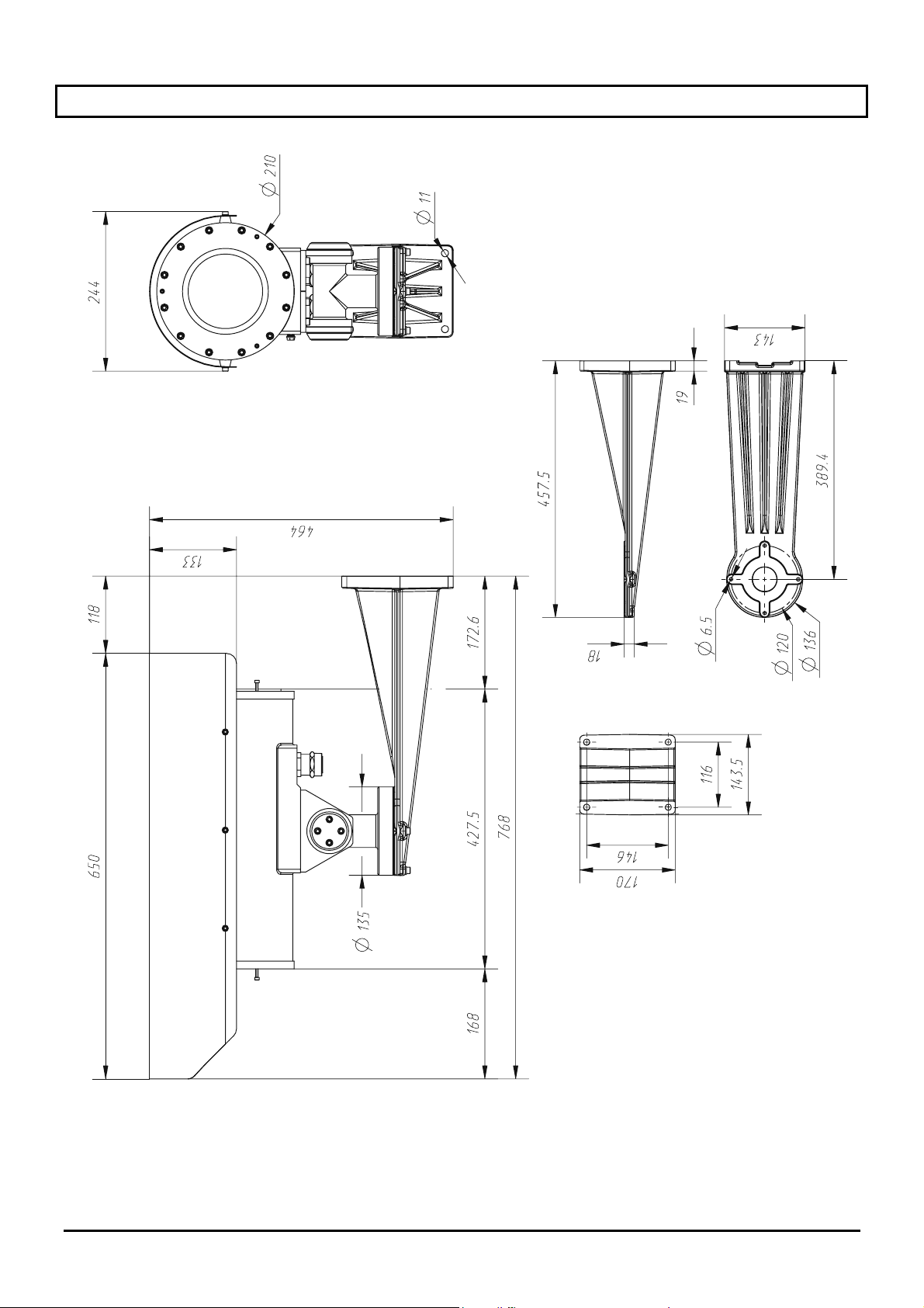
11 Dimensions caisson
Page 12 MNVCEXH_0702
Page 53
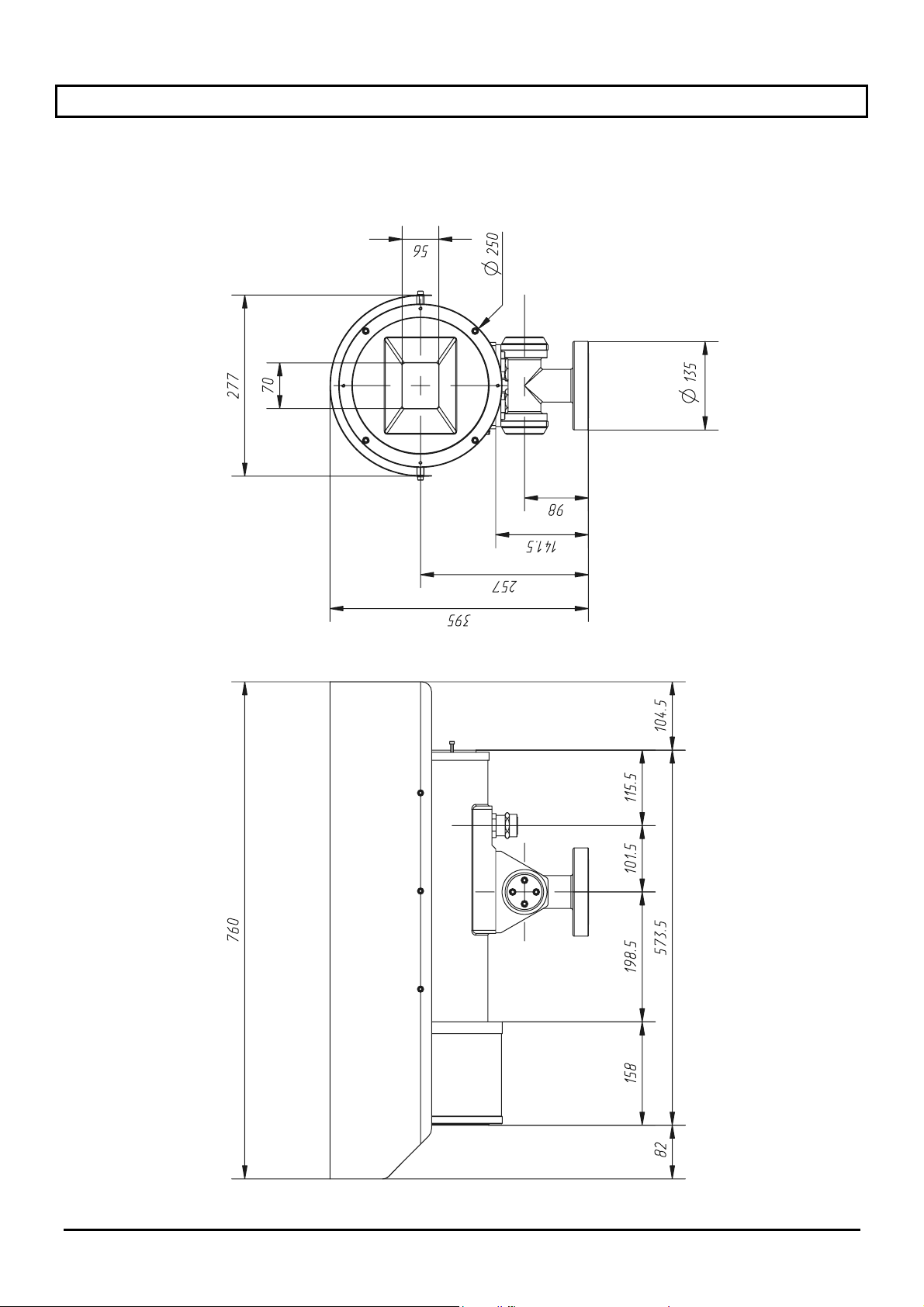
12 Caractéristiques techniques du dispositif de protection du verre
Dimensions (Ø x L, mm) Ø 250 x 140
Poids 8 Kg (22,5 kg avec caisson)
Alimentation 24V AC
Absorption 2 W
Page 13 MNVCEXH_0702
Page 54
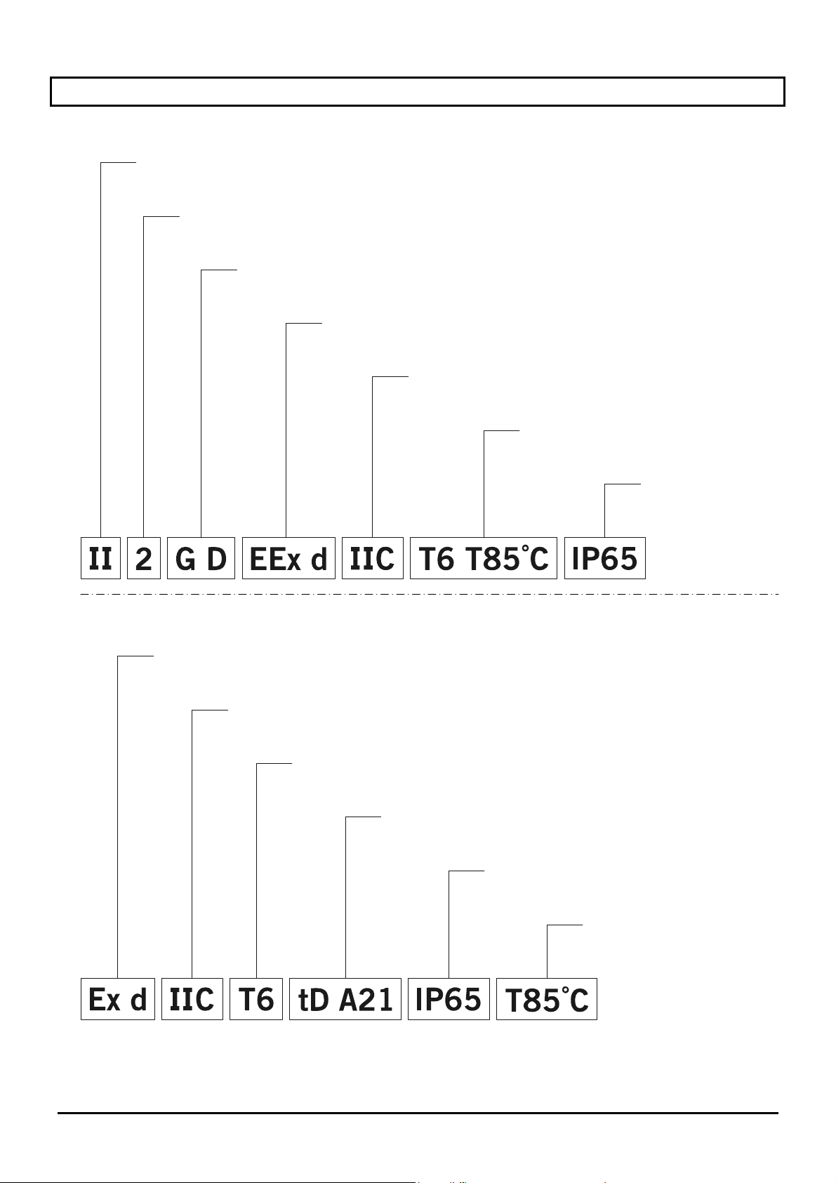
13 Annexe: Codification antidéflagrante
Certification ATEX
Groupe
(pour surfaces, mines exclues)
Catégorie (degré de protection élevé, les appareils de cette catégorie peuvent être employés
dans la zone 1 et 21 et dans la zone 2 et 22)
Type d’atmosphère
(gaz et poudres)
Caisson antidéflagrante pour environnement
potentiellement explosifs
Groupe
de gaz
Classification rélative
aux gaz et poudres
Degré de protection IP
du récipient
Certification IECEx
Caisson antidéflagrante pour environnement
potentiellement explosifs
Groupe
de gaz
Degré de protection
du récipient
Protection aux poudres inflammables,
pour zones de type 21-22
Degré de protection IP
du récipient
Temperature maximale
de surface
Page 14 MNVCEXH_0702
Page 55
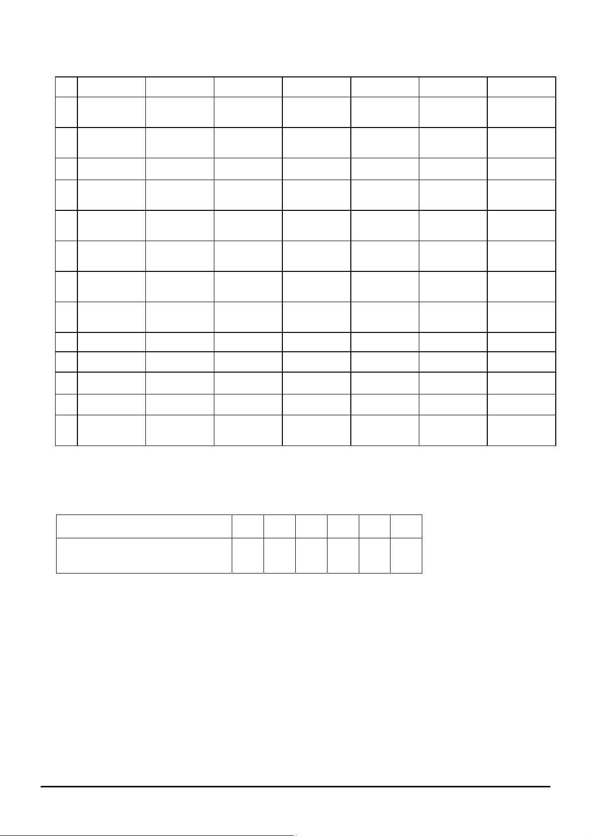
Le tableau suivant indique la classification de plusieurs gaz et vapeurs en fonction des groupes de protection
antidéflagrants et des températures.
I Méthane
T1 T2 T3 T4 T5 T6
(grisou)
IIA Acétone n-butane Essence Acétaldéhyde Nitrate
d'éthyle
Éthane n-butyle Diesel Éthyl éther
Éthylacétate Essence
avion
Ammoniaque Huile de
rinçage
Benzène
n-hexane
(pur)
Acide
acétique
Monoxyde de
carbone
Méthanol
Propane
Toluène
IIB Éthylène
IIC Hydrogène Acétylène Sulfure de
carbone
Remarques:
La classe de température supérieure couvre automatiquement les classes inférieures (T6 est supérieure à T1).
La classe IIB couvre également la IIA.
La classe IIC couvre également la IIB et IIA.
Classe de température
T1 T2 T3 T4 T5 T6
Température maximale de surface
450 300 200 135 100 85
(°C) du caisson (*) autorisée par la
classe correspondante
(*) Référence est généralement faite à une température ambiante de 50°C.
La plus basse température d'allumage des atmosphères explosives relatives doit être supérieure à la température
de surface maximale des caissons.
Page 15 MNVCEXH_0702
Page 56
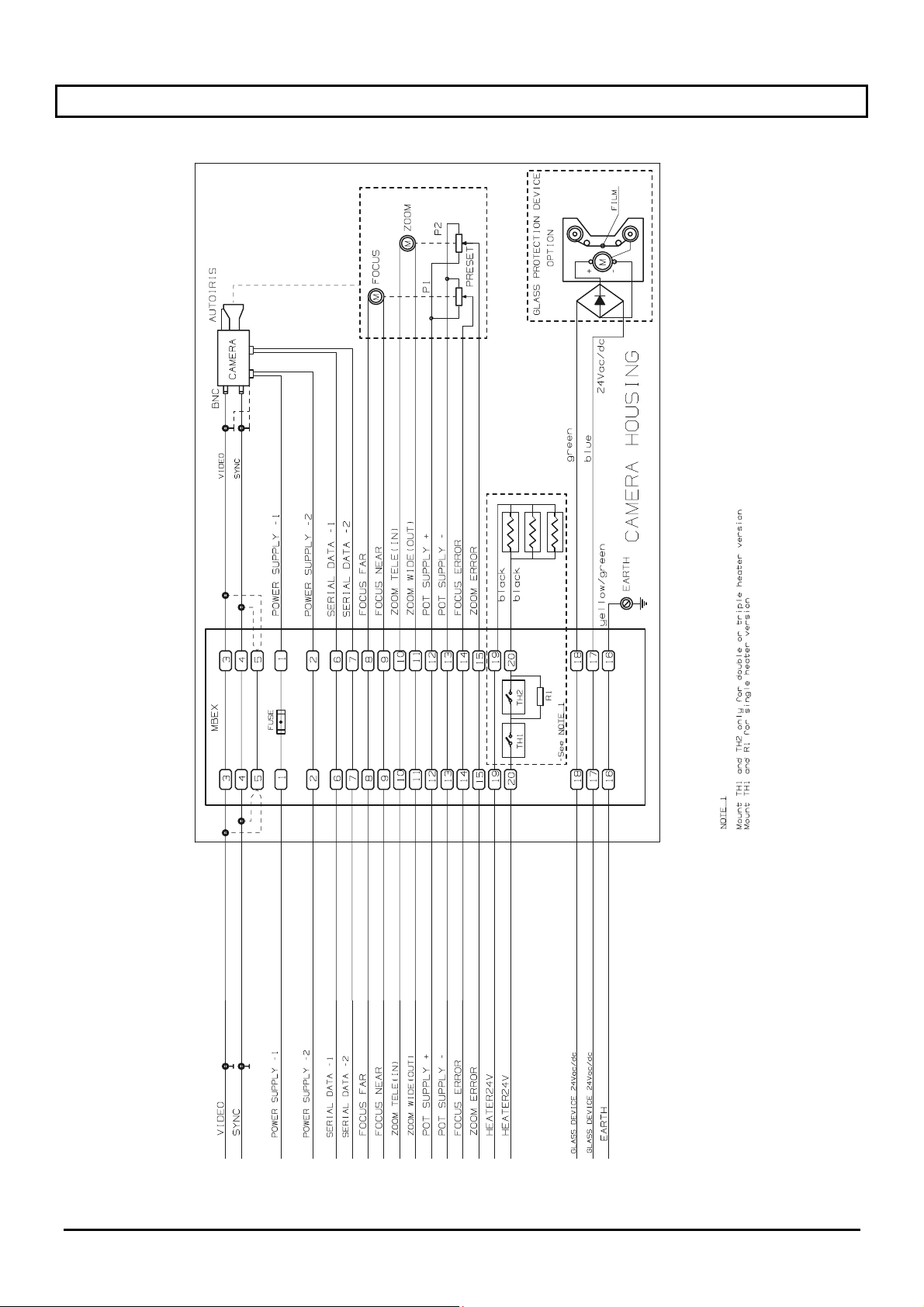
14 Annexe: schéma électrique
Page 16 MNVCEXH_0702
Page 57
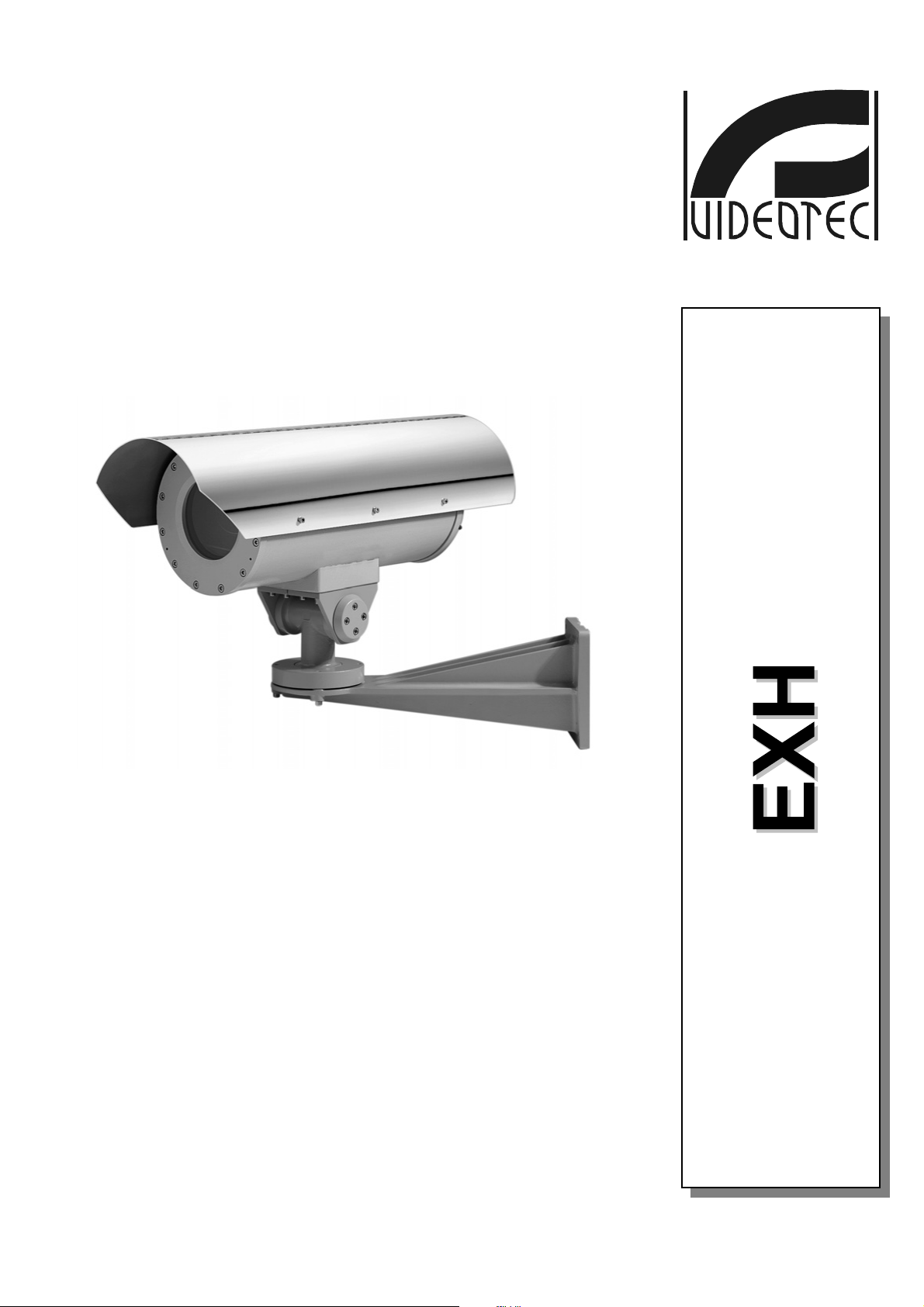
BEDIENUNGSANWEISUNG
Page 58

Page 59

INHALTSVERZEICHNIS
1 EINLEITUNG .............................................................................................................................................................3
1.1 Inhalt der Verpackung.........................................................................................................................................3
1.2 Inhalt der Bedienungsanleitung ..........................................................................................................................3
1.3 Verwendete Symbole..........................................................................................................................................3
2 SICHERHEITSMAßNAHMEN...................................................................................................................................4
3 KENNZEICHNUNG ...................................................................................................................................................5
4 BESCHREIBUNG GEHÄUSE EXH ..........................................................................................................................6
4.1 Glasschutz ..........................................................................................................................................................6
4.2 Verwendungsbereich ..........................................................................................................................................6
5 MONTAGE.................................................................................................................................................................7
5.1 Öffnen der Verpackung.......................................................................................................................................7
5.2 Überprüfung der Kennzeichnung........................................................................................................................7
5.3 Montage der Kamera ..........................................................................................................................................8
Anschluss des Gehäuses .........................................................................................................................................8
6 INBETRIEBSETZUNG ..............................................................................................................................................9
7 WARTUNG ..............................................................................................................................................................10
8 PROBLEMLÖSUNG ...............................................................................................................................................11
9 TECHNISCHE EIGENSCHAFTEN GEHÄUSE ......................................................................................................11
10 HÖCHSTWERTE INSTALLIERBARE KAMERAS EINSCHLIEßLICH OPTIK ...................................................11
11 ABMESSUNGEN GEHÄUSE ...............................................................................................................................12
12 TECHNISCHE EIGENSCHAFTEN GLASSCHUTZ..............................................................................................13
13 ANHANG: EXPLOSIONSSCHUTZ-CODIERUNG ...............................................................................................14
14 ANHANG: ELEKTRISCHER SCHALTPLAN.......................................................................................................16
Der Hersteller lehnt jegliche Verantwortung für Schäden zurück, die durch unsachgemäßen Gebrauch der in
dieser Anleitung erwähnten Geräte entstanden sich; er behält sich außerdem das Recht vor, den Inhalt der
Anleitung ohne Vorankündigung zu verändern. Bei der Erstellung und Überprüfung der Dokumentation dieses
Handbuchs wurde die größte Sorgfalt verwendet: dennoch kann der Hersteller keine Verantwortung für seine
Benutzung übernehmen. Das gleiche gilt für alle Personen oder Firmen, die an der Erstellung der Anleitung
beteiligt waren.
Seite 1 MNVCEXH_0702
Page 60

Für Informationen und Kundendienst wenden Sie sich an:
HEADQUARTERS ITALY FRANCE
VIDEOTEC S.p.A.
Via Friuli, 6
I-36015 SCHIO (VI) Italy
Tel. +39 0445 697411
Fax +39 0445 697414
[email protected]
www.videotec.com
VIDEOTEC FRANCE S.A.R.L.
Voie du Futur - Zac des Portes
27100 Val de Reuil, France
Tel. +33 2 32094900
Fax +33 2 32094901
[email protected]
www.videotec.com
UK / IRELAND
VIDEOTEC UK SALES
Tel. / Fax +44 (0)1353 775438
[email protected]
www.videotec.com
U.S.A. / CANADA
VIDEOTEC SECURITY, Inc.
The Lower level South Suite
The Ottilio Office Complex I
555 Preakness Ave.
TOTOWA, NJ 07512 - USA
Tel. +1 973 5950788
Fax +1 425 6484289
[email protected]
www.videotec.us
ASIA PACIFIC
VIDEOTEC (HK) Ltd
Unit 2,8/F, Vanta Industrial
Centre
21-33 Tai Lin Pai Road
Kwai Chung, NT, Hong Kong
Tel. +852 2333 0601
Fax +852 2311 0026
[email protected]
www.videotec.com.hk
Seite 2 MNVCEXH_0702
Page 61
1 Einleitung
1.1 Inhalt der Verpackung
• 1 explosionssicheres Gehäuse;
• 1 Bedienungsanleitung.
Überprüfen Sie beim Empfang der Ware, dass die Verpackung unversehrt ist und nicht heruntergefallen ist oder
beschädigt wurde.
Sollte die Verpackung deutliche Schäden aufweisen, informieren Sie umgehend den Lieferanten.
Kontrollieren Sie, dass die Verpackung das oben genannte Material enthält.
1.2 Inhalt der Bedienungsanleitung
Diese Bedienungsanleitung beschreibt die Gehäuse der Serie EXH und die entsprechenden Arbeitsschritte für
ihre Montage, Einstellung und Verwendung. Vor der Montage und der Verwendung des Empfängers sollte
dieses Handbuch unbedingt gründlich durchgelesen werden, vor allem das Kapitel über die
Sicherheitsvorschriften.
1.3 Verwendete Symbole
In diesem Handbuch werden verschiedene grafische Symbole verwendet, deren Bedeutung im folgenden
beschrieben wird:
Stromschlaggefahr; bevor man mit der Arbeit fort fährt, muss die Stromversorgung ausgeschaltet
werden, falls nicht ausdrücklich das Gegenteil angegeben ist.
Explosionsgefahr. Aufmerksam durchlesen, um Explosionsrisiken zu vermeiden.
Dieser Arbeitsschritt ist sehr wichtig für den korrekten Betrieb des Systems: der Vorgang sollte
aufmerksam durchgelesen und in der vorgeschriebenen Art und Weise durchgeführt werden.
Beschreibung der Systemeigenschaften: es wird empfohlen, diese gründlich zu lesen, damit man die
folgenden Schritte nachvollziehen kann.
Seite 3 MNVCEXH_0702
Page 62

2 Sicherheitsmaßnahmen
Das Gehäuse entspricht den während der Erstellung der Anleitung gültigen Vorschriften über Geräte
und Schutzvorrichtungen, die in explosionsgefährdeter Atmosphäre benutzt werden, über die
elektromagnetische Kompatibilität und allgemeine Anforderungen.
Damit das Personal (Fachinstallateur und Bediener) jedoch bei höchster Sicherheit arbeiten kann, sollten
folgende Hinweise befolgt werden:
• Überprüfen, dass alle Geräte dem Gebrauch und der Umgebung, für die sie gebaut wurden, entsprechen.
• Überprüfen, dass die angeschlossenen Geräte kompatibel und geeignet sind.
• Kontrollieren, dass die Betriebstemperaturen zu den Geräten passen.
• Die Geräte müssen so installiert werden, dass die Sicherheit der Anlage und des für die Montage
zuständigen Personals gewährleistet ist.
• Der Ort, an dem das Gerät installiert wird, sollte stabil genug sein, um dessen Gewicht tragen zu können,
dabei sollten auch besondere Umwelteinflüsse, wie z.B. starker Wind berücksichtigt werden.
• Es wird empfohlen, nur die für die Installation empfohlenen Bügel und Zubehörteile zu verwenden.
• Überprüfen, dass das Gerät fest und sicher angebracht ist.
• Da die Montagefläche vom Kunden selbst ausgewählt wird, werden keine Schrauben mitgeliefert, die eine
sichere Befestigung des Geräts an der Fläche gewährleisten. Der Installateur ist dafür verantwortlich, die
speziell dafür geeigneten Schrauben zu verwenden.
• Die Montage und Wartung des Geräts (sowie der ganzen Anlage, deren Teil es ist) muss von ausreichend
qualifiziertem Fachpersonal durchgeführt werden, das die landesweit geltenden Vorschriften für die
Sicherheit des Personals einzuhalten hat.
• Es sollten geeignete Werkzeuge verwendet werden. Es kann unter Umständen sein, dass aus
Montagegründen spezielle Werkzeuge erforderlich sind, je nachdem, wo die Vorrichtung angebracht wird.
• Überprüfen, dass die Montage die örtlichen Sicherheitsvorschriften erfüllt.
• Das Gerät sollte außerhalb der Reichweite des Kunden oder irgendwelcher anderer Personen, die zufällig
damit in Berührung kommen könnten, montiert werden.
• Das Gerät sollte an eine Stromleitung angeschlossen werden, die der auf den Kennzeichnungsschildern
entspricht (siehe folgendes Kapitel Kennzeichnung).
• Vor dem Versetzen des Geräts bzw. der Durchführung technischer Eingriffe muss es von der Stromleitung
getrennt werden.
• Das Gerät darf nur von qualifiziertem Fachpersonal geöffnet werden, in nicht explosionsgefährdeter
Atmosphäre. Sobald am Gerät Veränderungen vorgenommen werden, verfällt die Garantie.
• Das Gerät darf keinesfalls von Kindern oder unbefugten Personen benutzt werden.
• Erst, wenn das Gerät von der Stromversorgung getrennt ist und die Anschlusskabel zu anderen
Vorrichtungen entfernt wurde, ist es tatsächlich ausgeschaltet.
• Vor dem Anschließen des Geräts an die Stromversorgung, sollte an der elektrischen Anlage des Gebäudes
eine Schutzvorrichtung installiert werden.
• Es ist dem Bediener untersagt, andere Vorrichtungen in das Gerät einzubauen, die gefährliche Strahlungen
erzeugen könnten.
• Für den Kundendienst wenden Sie sich bitte ausschließlich an autorisiertes Fachpersonal.
• Diese Bedienungsanleitung sollte sorgfältig aufbewahrt werden, damit sie für eine zukünftige Benutzung zur
Verfügung steht.
Das Gerät muss an Erde gelegt werden!
Seite 4 MNVCEXH_0702
Page 63
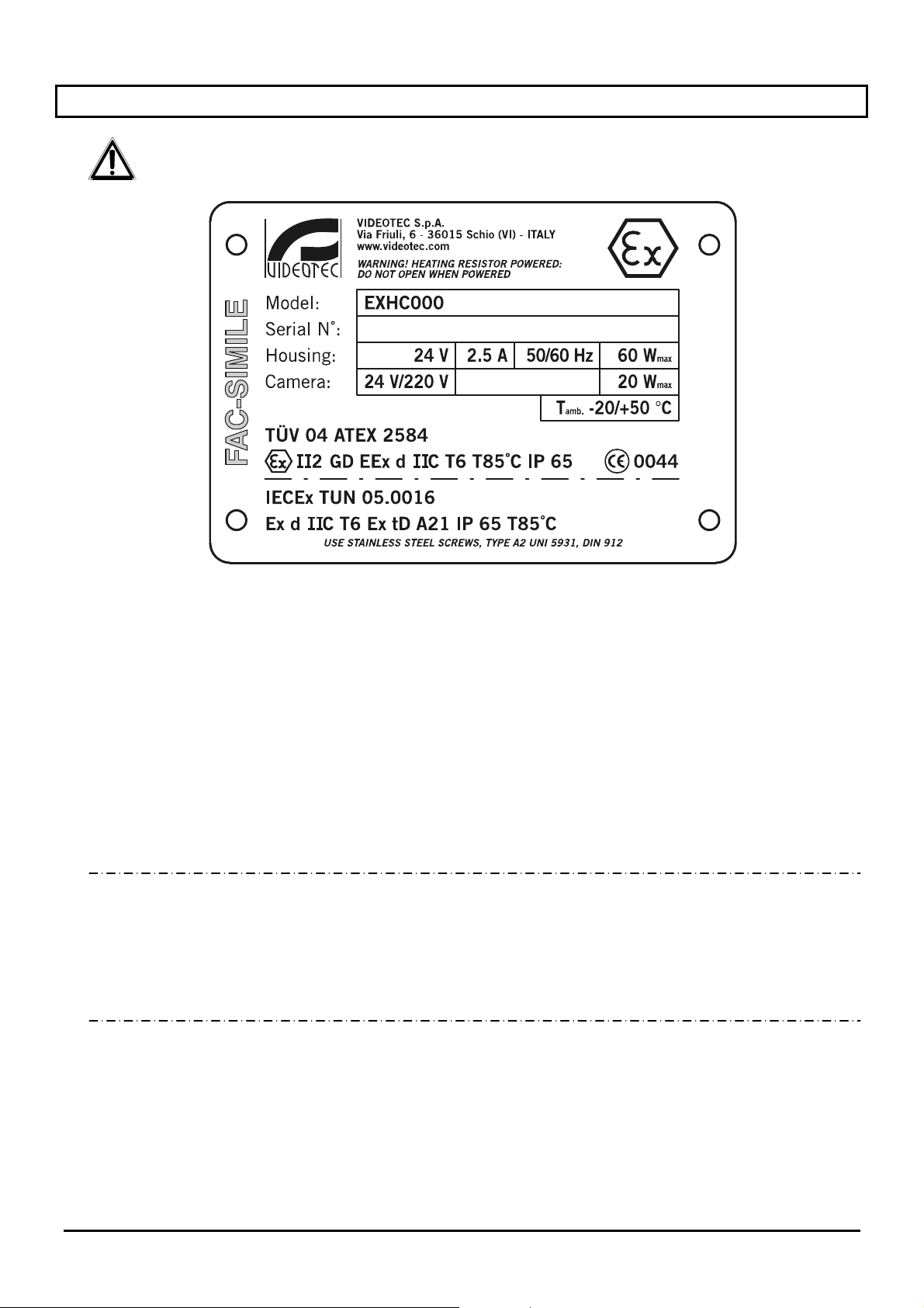
3 Kennzeichnung
Auf dem Gehäuse der Serie EXH finden sich folgende Informationen:
• Symbol
• Name und Anschrift des Herstellers
• Kennnummer des Modells
• Serienmummer
• Gehäuse:
• Versorgungsspannung (V)
• Stromaufnahme (A)
• Frequenz (Hz)
• Gehäuseverbrauch (W)
• Kamera:
• Versorgungsspannung (V)
• Höchstverbrauch (W) – (die Angaben zur Videokamera beziehen sich auf die Werte der Spannung und
• Temperaturwerte in der Arbeitsumgebung für die Kennnummer des Modells
• ATEX-Bescheinigungsnummer
• Einstufung des Zonentyps, Schutzmethode und Temperaturklasse, für die der Einsatz dieses
Produktes nach der Richtlinie ATEX zulässig ist.
• Schutzart IP
• EG-Kennzeichnung
• Nummer der benannten Stelle, welche die ATEX-Bescheinigung ausgestellt hat
• IECEx-Bescheinigungsnummer
• Typeneinstufung der Zone, Schutzmethode und Temperaturklasse, für die der Einsatz dieses
Produktes nach der Vorschrift IECEx zulässig ist.
Vor der Montage sollte kontrolliert werden, dass die Stromversorgung und Schutzvorrichtungen des Geräts den
Anforderungen entsprechen. Die Verwendung von Geräten, die nicht geeignet sind, kann die Sicherheit des
Personals und der Anlage stark gefährden.
b
des maximalen Verbrauches, die für den Kamerabetrieb zulässig sind)
Seite 5 MNVCEXH_0702
Page 64

4 Beschreibung Gehäuse EXH
Das explosionssichere Gehäuse der Serie EXH wurde für die Verwendung von Kameras in
Betriebsumgebungen mit explosionsgefährdeter Atmosphäre entwickelt, z.B. durch Gase, Dämpfe, Nebel oder
Staub-/Luftgemische.
Die Gehäuse EXH bestehen aus einer massiven Aluminiumgußlegierung Anticorodal der Gruppe AlSi7Mg EN
AC-42000, deren chemische Zusammensetzung von der Norm UNI EN 1706 definiert ist.
Je nach Modell werden sämtliche Elemente im Ofen beschichtet oder mit besonderen Überzügen beschichtet,
die äußerst beständig gegen ultraviolette Stahlungen, Salznebel und Luftschadstoffe sind.
Sie werden nach den Vorgaben der Richtlinie 94/9/EG ATEX und der Protokolle IEC 60079-0:2000, IEC 600790:2001 sowie IEC 61241-1:2004 hergestellt.
Der Kamerakörper besteht aus einem zylinderförmigen Rohr mit einem Flansch, auf dem sich ein starkes
durchsichtiges Glas befindet; auf der anderen Seite des Glases ist ein weiterer Flansch angebracht, der zum
einen den Zylinder abschließt und zum anderen die Befestigungsplatte für die Kamera hält. Der Schutzgrad
IP65 wird auch von den beiden Kabelklemmen 3/4” GAS gewährleistet, in die die Betriebskabel mit einem
Durchmesser von 14 bis 17 mm eingeführt werden.
Werden Wärmekameras eingesetzt, die abgestrahlte Wärme erfassen können, so muss auf der Frontseite des
Gehäuses ein spezieller Filter verwendet werden. Er besteht vorwiegend aus Germanium und ist so aufgebaut,
dass dieselben Festigkeits- und Sicherheitseigenschaften garantiert sind, wie beim Standardglas.
Die Ausführung des Gehäuses ist nach den Vorgaben der Richtlinie 94/9/EG Atex gefertigt.
Das Gehäuse kann zudem mit folgendem Zubehör ausgestattet werden:
• Sonnenschutzabdeckung (EXHS);
• Gelenkbügel für die Wandbefestigung (EXWBJ);
4.1 Glasschutz
Die explosionssicheren Gehäuse der Serie EXH können mit einem Glasschutz ausgestattet werden, der an der
vorderen Öffnung des Gehäuses angebracht wird. Er besteht aus einem Flansch zur Verbindung mit dem
Gehäuse, einem Verschlussflansch und einem explosionssicheren Mittelteil, das ein starkes durchsichtiges
Glas enthält, einem Gleichstrommotor mit 24VDC-Speisung, zwei Aufrollvorrichtungen und einer durchsichtigen
Mylarfolie, die vor dem Glas angebracht ist. Der Motor steuert mit vier verzahnten Kegelritzeln die
Aufrollvorrichtungen, von denen eine die schmutzige Folie aufrollt, während die andere die saubere Folie
abrollt. Der Motor ist über einen ON-OFF-Doppelleiterkontakt (ein normaler und einer + 24VDC) ferngesteuert.
Die Steuereinheit des Glasschutzes muss vom Kunden bereitgestellt werden!
Die durchsichtige Mylarfolie kann ca. 350 Mal weitertransportiert werden. Wenn sie zu verschmutzt ist, schaltet
der Bediener den Motor ein und transportiert die Folie so lange, bis die Bildfläche wieder sauber ist (die
schmutzige Folie muss um ca. 50 mm weitertransportiert werden). Das Ende der Folie wird durch Markierungen
auf den letzten 50 cm der Folie angezeigt.
Die Folie kann auch automatisch durch eine Zeitplansteuerung weitertransportiert werden, mittels eines
entsprechenden Steuerungssystems (nicht in der Lieferung inbegriffen).
Zur Auswechslung der Folie den vorderen Flansch öffnen und die Aufrollvorrichtungen herausnehmen. Die
schmutzige Folie durch eine saubere ersetzen.
4.2 Verwendungsbereich
Das Gehäuse wird fest installiert und dient zur Überwachung explosiver Atmosphären der Klasse 1-21
oder 2-22, mittels einer vom Bediener eingebauten Kamera.
• Das Gehäuse EXH wurde nach der Richtlinie 94/9/EG ATEX und den Protokollen IEC 60079-0:2000, IEC
60079-0:2001, IEC 61241-1:2004 gebaut und zertifiziert. Die genannten Vorschriften legen den
Anwendungsbereich und die mindestens notwendigen Sicherheitsanforderungen fest.
Seite 6 MNVCEXH_0702
Page 65
5 Montage
Die Installation darf ausschließlich von qualifiziertem Fachpersonal durchgeführt werden.
Die Anschlüsse und Labortests sollten vor der endgültigen Montage durchgeführt werden.
Geeignete Werkzeuge benutzen.
Die folgenden Arbeitsschritte sollten bei abgetrennter Stromversorgung ausgeführt werden,
sofern keine anderweitigen Anweisungen vorliegen.
Vor der Montage des Geräts muss an der elektrischen Anlage eine Schutzvorrichtung
installiert werden.
Die angegebenen Leistungen nicht überschreiten.
Die Schrauben des Gehäuses nicht durch andere Schraubentypen ersetzen.
Alle Anschlüsse in nicht explosionsgefährdeter Atmosphäre durchführen.
5.1 Öffnen der Verpackung
Wenn die Verpackung keine offensichtlichen Schäden aufweist (durch Herunterfallen oder evtl.
Schleifspuren), kontrollieren, dass sie das in der Liste des Abschnitts Inhalt der Verpackung im Kapitel
Einführung genannte Material enthält.
Das gesamte Verpackungsmaterial ist wieder verwertbar. Der Fachinstallateur ist dafür zuständig, dass
es getrennt bzw. gemäß den im entsprechenden Land geltenden Vorschriften entsorgt wird.
5.2 Überprüfung der Kennzeichnung
Vor der Montage sollte anhand der Kennzeichnungsschilder (siehe Beschreibung im Kapitel
Kennzeichnung) kontrolliert werden, ob das gelieferte Material über die geforderten Spezifikationen
verfügt. Keinesfalls Veränderungen vornehmen bzw. Anschlüsse, die nicht in dieser Anleitung
beschrieben sind, durchführen: die Verwendung von nicht geeigneten Geräten kann die Sicherheit des
Personals und der Anlage stark gefährden.
Seite 7 MNVCEXH_0702
Page 66
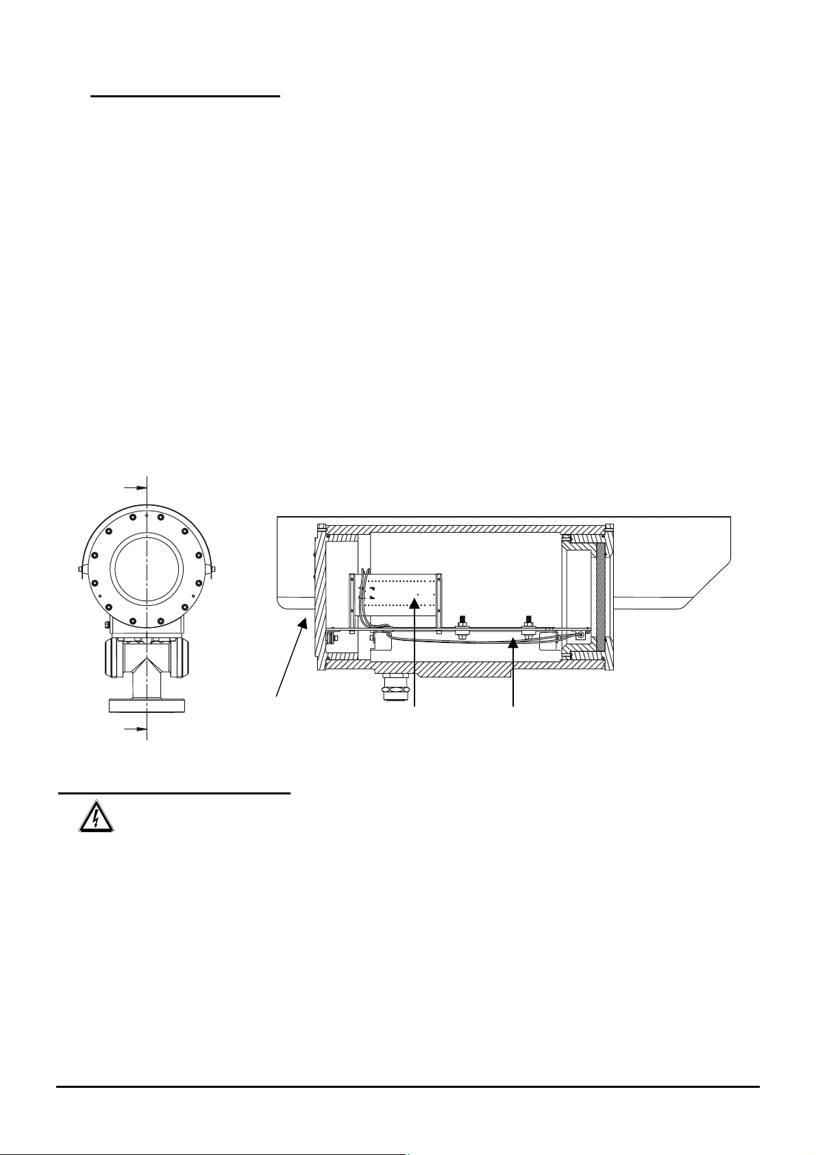
5.3 Montage der Kamera
Wir weisen das Installationspersonal darauf hin, keine Geräte zu verwenden, die die Spezifikationen
überschreiten!
Wir weisen das Installationspersonal darauf hin, keine Geräte zu verwenden, von denen gefährliche
Strahlungen ausgehen!
Der hintere Flansch des Gehäuses ist mit 12 M6-Schrauben versehen und mit drei Schrauben, die im 120°Winkel angebracht sind, um das Abnehmen des Flansches zu erleichtern. Sobald man nämlich die Schrauben
mit M6-Gewinde entfernt hat und die drei Schrauben im 120°-Winkel anzieht (immer abwechselnd jeweils um
eine Drehung), kann man ihn leichter abnehmen.
Für die Montage der Kamera muss der Verschlussflansch des Gehäuses, der auch die Befestigungsplatte für
die Kamera mit dem entsprechenden Klemmenbrett hält, entfernt werden. Diese Platte liegt auf zwei am
Gehäuse befestigten Führungen; entfernt man den Flansch, kann man die Platte an den Führungen
herausziehen und die Kamera mit ihrem Zubehör bequem montieren und anschließen. Während der Montage
sollte die Kamera mit Hilfe der eigens dafür mitgelieferten Abstandstücke von der Befestigungsplatte isoliert
werden.
Das Gehäuse kann entweder mit den eigens dafür vorgesehenen Gelenkstückeck mit vier M6-Bohrungen im
90°-Winkel befestigt werden sowie eventuell mit dem Bügel, für den vier M8-Bohrungen vorgesehen sind.
(Siehe Einzelheiten der folgenden Zeichnung bzw. des elektrischen Schaltplans im Anhang.)
Nach Montage der Kamera muss der Flansch wieder korrekt angebracht werden. Die 12 Verschlussschrauben
sollten auf einen Anzugsmoment von 12,5 Nm gebracht werden.
Flansch
Klemmenbrett
Befestigungsplatte Kamera
Anschluss des Gehäuses
Achtung: vor Durchführung der folgenden Arbeitsschritte überprüfen, dass die Netzspannung
ordnungsgemäß funktioniert.
Für den Anschluss des Gehäuses an die Stromleitung sollten Kabel benutzt werden, die für die Verwendung in
explosionsgefährdeter Atmosphäre geeignet sind; anschließend folgende Arbeitsschritte durchführen:
• die Kabel mit den eigens mitgelieferten Kabelklemmen an das Gehäuse anschließen;
• Anschlüsse an die Kamera und Optik durchführen;
• das Gerät mit Strom versorgen;
• Funktionsprüfungen durchführen.
Seite 8 MNVCEXH_0702
Page 67
6 Inbetriebsetzung
Vor der Inbetriebsetzung sollte man:
• Die vorliegende Bedienungsanleitung gründlich und vollständig durchlesen;
• Die Kamera und Optik korrekt montieren;
• Das positive Ergebnis der Funktionsprüfung abwarten;
• Eine ordnungsgemäße Stromleitung installieren.
Folgende Sicherheitsvorschriften sollten eingehalten werden:
• Da die Anlage ein großes Gewicht hat, muss für ihren Transport bzw. ihre Versetzung eine geeignete
Ausrüstung verwendet werden;
• Vor der Durchführung von Eingriffen kontrollieren, dass die Stromzufuhr unterbrochen ist;
• Bevor man das Gerät mit Strom versorgt, sollte an der elektrischen Anlage des Gebäudes eine
Schutzvorrichtung installiert werden.
• Überprüfen, dass alle Sicherheitsmaßnahmen in Bezug auf die Unversehrtheit des Personals getroffen
wurden.
• Der elektrische Anschluss der Anlage muss den geltenden örtlichen Vorschriften entsprechen.
Es sollten folgende Maßnahmen zur Verhinderung von Explosionen getroffen werden:
• Die ausgewählte Auflagefläche sollte fest und stabil sein;
• Es sollte ein geeigneter Tragbügel ausgewählt werden (sofern er benutzt wird);
• Die verwendeten Werkzeuge sollten dem Arbeitsbereich angemessen sein;
• Das Gehäuse nicht öffnen, wenn die Atmosphäre möglicherweise explosionsgefährdet ist;
• Nur sichere und dauerhafte Befestigungssysteme und Schrauben verwenden.
Es wird nochmals darauf hingewiesen, dass das Gerät an eine ordnungsgemäße Erdleitung
gelegt werden muss!
Nach der Inbetriebsetzung muss die vorliegende Bedienungsanleitung für die zukünftige Benutzung aufbewahrt
werden.
Seite 9 MNVCEXH_0702
Page 68
7 Wartung
Am Gehäuse Serie EXH sind keine besonderen Wartungseingriffe nötig.
Man kann dennoch unterscheiden zwischen:
Ordentlicher Wartung (regelmäßig):
• Reinigung des Glases: mit Wasser oder einem anderen, ungefährlichen Reinigungsmittel;
• Reinigung des Geräts
der Außenfläche bildet. Die Häufigkeit der Wartungseingriffe hängt von der Umgebung ab, in der das
Gehäuse verwendet wird;
• Überprüfung der Kabel
Gefahrensituationen führen könnte; gegebenenfalls muss ein außerordentlicher Wartungseingriff
durchgeführt werden;
• Auswechslung der Mylarfolie
Sicherheitsbedingungen gemäß Kapitel Inbetriebsetzung erfolgen. Für diesen Arbeitsschritt müssen die vier
Befestigungsschrauben der Abdeckung des Glasschutzes aufgeschraubt und die Rollen mit der
schmutzigen Folie durch andere Rollen mit sauberer Folie ersetzt werden, indem man diese einfach abzieht.
Außerordentliche Wartung (nur in besonderen Fällen):
• Auswechslung der vorderen, mit Glas versehenen Einheit (oder Glasschutz, bei Ausführungen, in denen
dieser vorgesehen ist);
• Auswechslung der internen Schlitteneinheit mit Verkabelung für die Heizung und elektrischer
Verbindungskarte mit dem jeweils geeigneten Ersatzteil für die Ausführung mit oder ohne Glasschutz;
• Auswechslung der Kabelklemmen;
• Abnutzung und gefährliche Beschädigungen des Kabels;
• Fehlfunktion der Kamera bzw. Optik;
• Verpuffung im Inneren oder in der Nähe des Gehäuses;
• Jeder andere Umstand, aufgrund dessen das Gehäuse geöffnet werden muss.
In allen Fällen wird empfohlen, die am Gehäuse notwendigen Eingriffe in einer Werkstatt durchzuführen.
: sollte regelmäßig durchgeführt werden, damit sich keine zu große Staubschicht auf
: diese dürfen keine Zeichen von Abnutzung oder Beschädigung aufweisen, was zu
(bei Ausführung mit Glasschutz): muss unter den allernötigsten
Bei einer Beschädigung anderer betroffener Teile als der genannten muss die Auswechslung
oder Reparatur vom Hersteller durchgeführt werden!
Bei jeder Auswechslung der genannten Teile dürfen ausschließlich originale Ersatzteile von
VIDEOTEC benutzt werden, wobei die Wartungsanweisungen im Anhang der Ersatzteilkits genauestens
befolgt werden müssen.
Der Hersteller lehnt jede Verantwortung für eventuelle Schäden an allen in dieser Anleitung
erwähnten Geräten ab, die aufgrund von Beschädigung, Verwendung nicht originaler Ersatzteile oder
Montage-, Wartungs-/Reparaturarbeiten, die von unzureichend ausgebildetem Personal durchgeführt
wurden, entstanden sind.
Seite 10 MNVCEXH_0702
Page 69
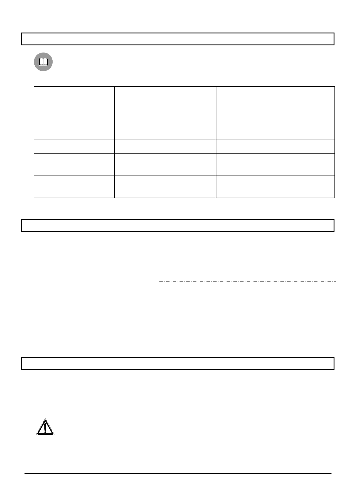
8 Problemlösung
Auch wenn sich das Gehäuse der Serie EXH durch seine einfache Benutzung auszeichnet, können
dennoch Probleme auftreten, sowohl während der Montage als auch während des Betriebs.
PROBLEM MÖGLICHE URSACHE ABHILFE
Die Kamera schaltet sich
nicht ein
Die Kamera ist
eingeschaltet, aber es ist
kein Bildsignal vorhanden
Die Optik funktioniert nicht
Die Heizung funktioniert
nicht
Das von der Kamera
aufgenommene Bild ist
ungenau
• Fehlende Stromzufuhr
• Sicherung durchgebrannt
• Falsche Anschlüsse • Die Anschlusskabel kontrollieren
• Falsche oder fehlende optische
Spannung
• Das Thermostat wurde nicht
ausgelöst
• Falsche Anschlüsse
• Falsche Einstellungen der Optik
• Funktionsstörungen der Kamera
• Speisekabel kontrollieren
• Sicherung auswechseln
• Die Spannung an der Optik
kontrollieren
• Die Temperatur des Thermostats
kontrollieren
• Die Anschlusskabel kontrollieren
• Die Einstellungen der Kamera
überprüfen
• Die Kamera auswechseln
9 Technische Eigenschaften Gehäuse
Innenmaße Gehäuse
(Ø x B, mm)
Gewicht Gehäuse 14,5 kg (22,5 kg mit Glasschutz)
Gewicht Gelenk 3,5 kg
Mechanischer Schutzgrad IP 65
Ausführung II 2 GD EExd IIC T6 T85°C IP 65 ATEX
Betriebstemperatur
Stromversorgung 24/240V AC, 50/60 Hz
Aufnahme 20/40/60 W (Je nachdem, welche Heizung in das Gehäuse
Ø 180 x 380 (460 mit Glasschutz)
Ex d IIC T6 Ex tD A21 T85°C IP 65 IECEx
-20°C ÷ + 50°C
-40°C ÷ + 50°C (Nur bei den Ausführungen mit dreifacher
Heizung)
eingebaut ist)
10 Höchstwerte installierbare Kameras einschließlich Optik
Nutzraum Kamera (B x H x T, mm) 100 x 100 x 280 (360 mit Glasschutz)
Maximalleistung 20W
Maximalspannung 240V
Achtung: Die Gehäuse-Speisung muß die gleiche wie die
Heizung sein
Seite 11 MNVCEXH_0702
Page 70
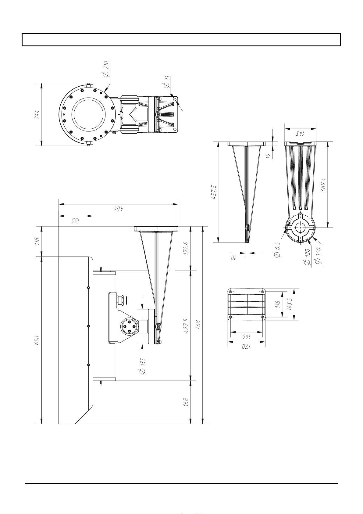
11 Abmessungen Gehäuse
Seite 12 MNVCEXH_0702
Page 71
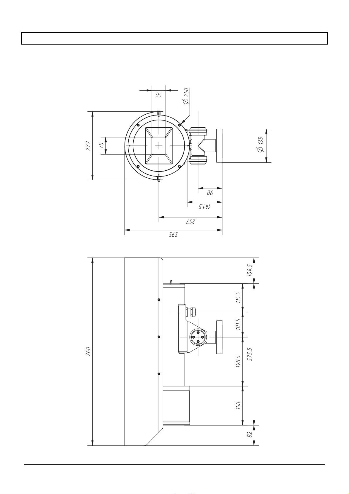
12 Technische Eigenschaften Glasschutz
Maße (Ø x B, mm) Ø 250 x 140
Gewicht 8 kg (22,5 kg mit Gehäuse)
Stromversorgung 24V AC
Aufnahme 2 W
Seite 13 MNVCEXH_0702
Page 72
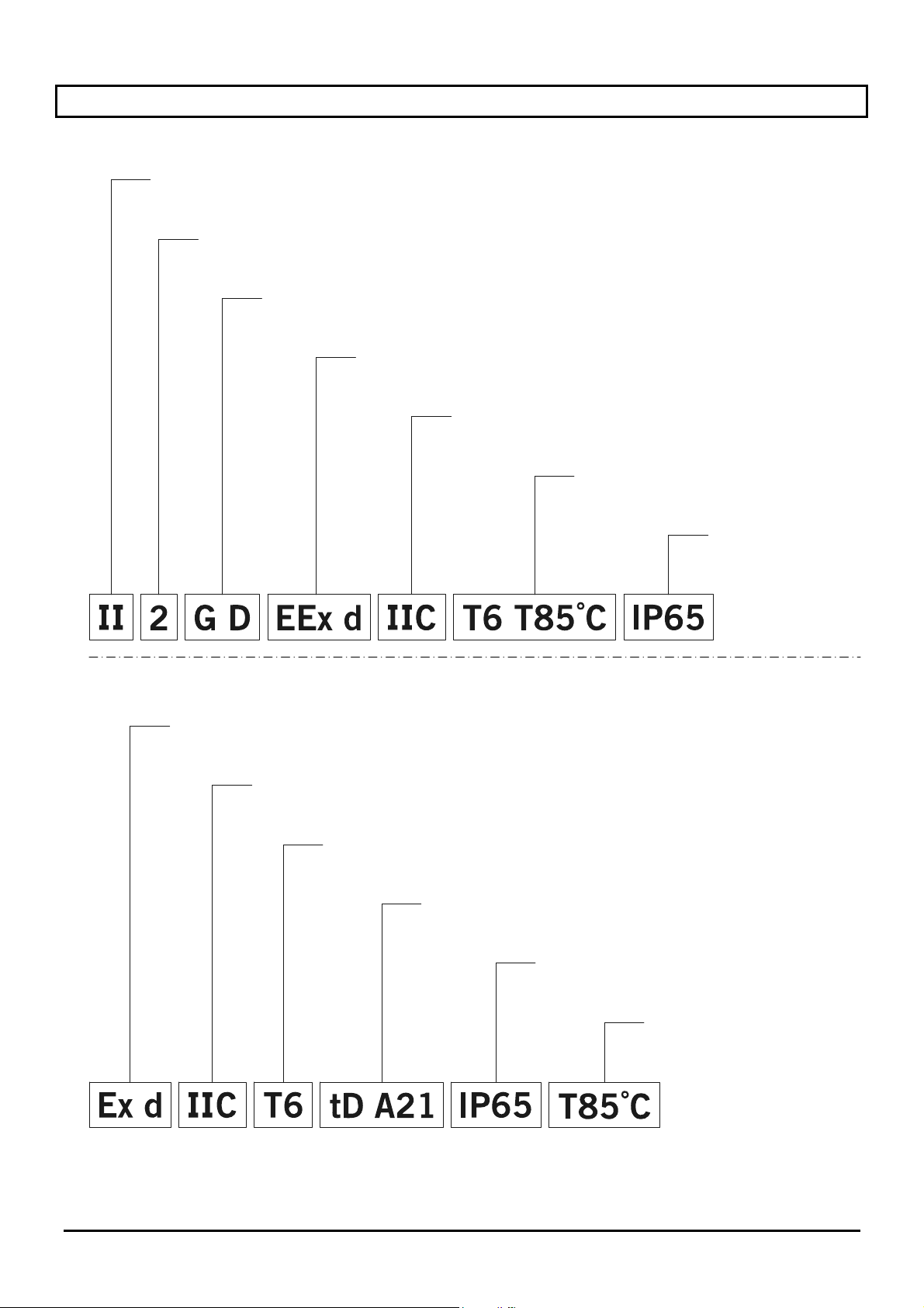
13 Anhang: Explosionsschutz-Codierung
ATEX-Zertifizierung
Gruppe
(Vorrichtungen für Oberfläche, nicht Bergwerk)
Klasse (hoher Sicherheitsgrad, die Vorrichtungen dieser Gruppe können in den Zonen 1, 2,
21 und 22 Zonen installiert werden)
Atmosphäre
(Gase und Pulver)
Explosionsichere Gehäuse
für explosion gefährdeten Bereichen
Schutzgruppe
Temperaturklassifizierung
für Gase und Pulver
IP
Schutzartgehäuse
IECEx-Zertifizierung
Explosionsichere Gehäuse
für explosion gefährdeten Bereichen
Schutzgruppe
Temperaturklasse
der Vorrichtung
Beschützung gegen entflammbare
Stäube für Zonen 21-22
IP
Schutzart-gehäuse
Maximale oberflächliche
Temperatur
Seite 14 MNVCEXH_0702
Page 73
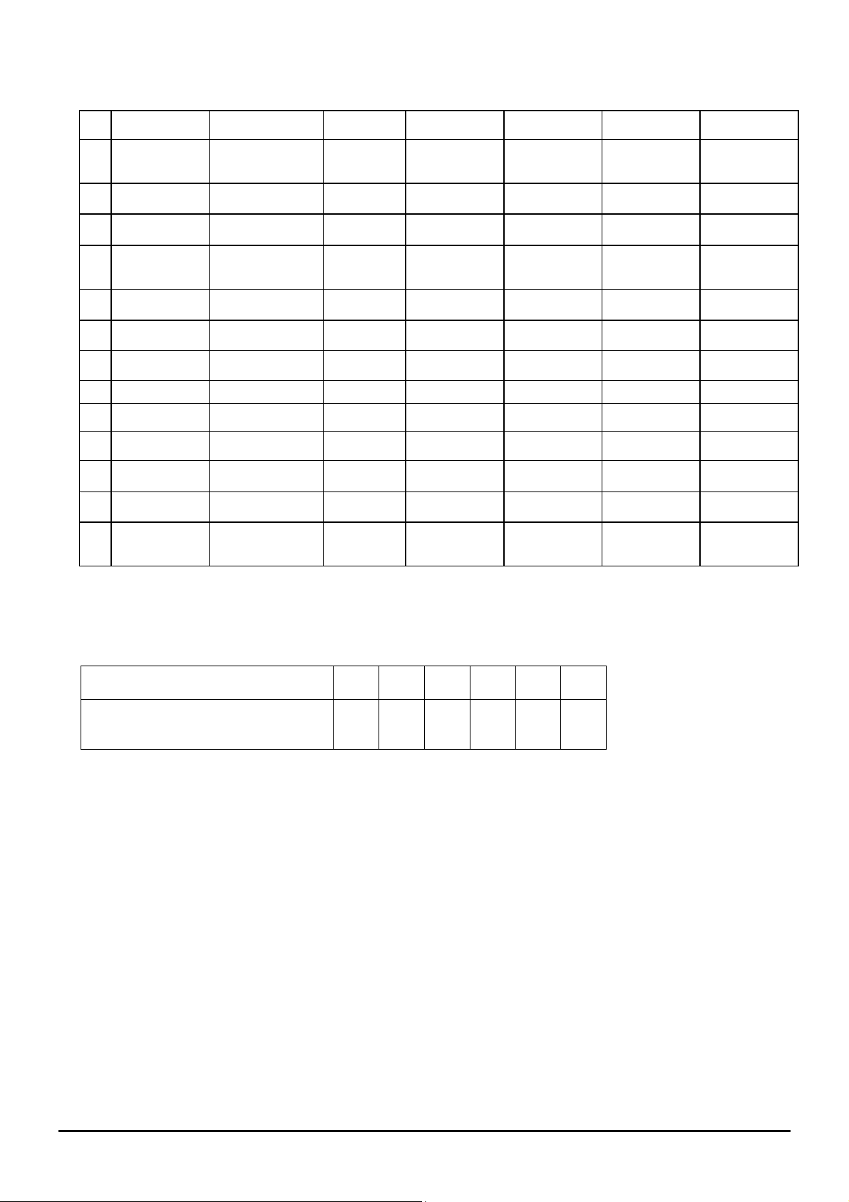
Die Tabelle unten enthält die Klassifizierung einiger Gase und Dämpfe auf Basis der Explosionsschutzgruppen
und Temperaturen.
I Methan
T1 T2 T3 T4 T5 T6
(Grubengas)
IIA Aceton n-Butan Benzin Acetaldehyd Äthylnitrat
Äthan n-Butyl Dieselöl Äthyläther
Äthlacetat Flugzeug-
kraftstoff
Ammoniak Heizöl
Benzen (rein) n-Hexan
Essigsäure
Kohlenmonoxyd
Methanol
Propan
Toluol
IIB Äthylen
IIC Wasserstoff Acetylen Schwefel-
kohlenstoff
Anmerkungen:
Die höhere Temperaturklasse deckt automatisch die unteren ab (T6 ist besser als T1).
Die Klasse IIB deckt auch IIA ab.
Die Klasse IIC deckt auch IIB und IIA ab.
Temperaturklasse
T1 T2 T3 T4 T5 T6
Maximale zugelassene Temperatur
450 300 200 135 100 85
(°C) der Gehäuseoberfläche (*)
gemäß der entsprechenden Klasse
(*) Normalerweise bezogen auf eine Umgebungstemperatur = 50°C. Die niedrigste Entzündungstemperatur der
entsprechenden explosiven Atmosphäre muss höher als die maximale Temperatur der Gehäuseoberfläche
sein.
Seite 15 MNVCEXH_0702
Page 74
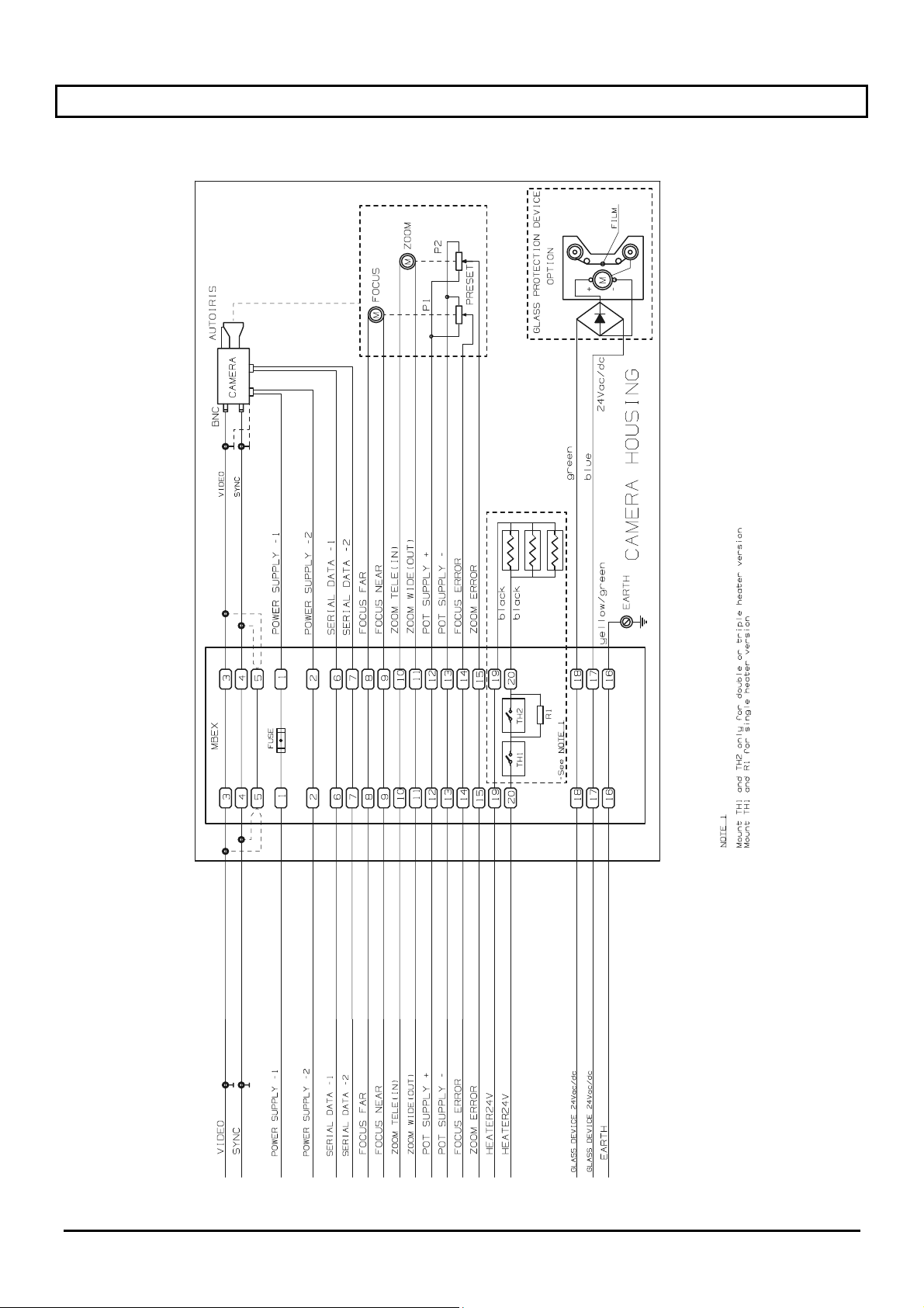
14 Anhang: Elektrischer Schaltplan
Seite 16 MNVCEXH_0702
Page 75

Videotec S.p.A.
Sede Legale: Via Friuli, 6 - I-36015 SCHIO (VI)
Telefono ++39 0445 697411 - Telefax ++39 0445 697414
R.E.A. n. 189121/Vicenza - Registro Imprese n. 19533//VI116
M/VI 018155 - Capitale Sociale € 520.000,00 int. versato
Codice Fiscale 00882600240 - Partita I.V.A. IT00882600240
e-mail: [email protected] - url: www.videotec.com
Dichiarazione di conformità
Declaration of conformity
La Ditta Videotec S.p.a., Via Friuli 6 Schio (VI), dichiara sotto la sua responsabilità che i prodotti:
Videotec S.p.a., having its head office in Schio (VI) Italy Via Friuli 6, declares under its responsibility that the products:
Serie EXH Custodia antideflagrante EEx d per telecamera
Housing explosion-proof EEx d for camera
ai quali questa dichiarazione si riferisce sono conformi ai seguenti documenti normativi:
to whom this declaration refers are in conformity with the following standards:
EN 50014 : 1997 Costruzioni elettriche per atmosfere potenzialmente
EN 50018 : 2000 Costruzioni elettriche per atmosfere potenzialmente
EN 50281 : 1999 Costruzioni elettriche destinate all’uso in ambienti con
IEC 60079-0 : 2000
Edition 3.1
IEC 60079-1 : 2001
Edition 4
IEC 61241-0 : 2004
Edition:1
IEC 61241-1 : 2004
Edition:1
esplosive. Regole generali
esplosive. Custodie a prova di esplosione 'd'
presenza di polvere combustibile
Costruzioni elettriche per atmosfere potenzialmente
esplosive. Part.0: Regole generali
Costruzioni elettriche per atmosfere potenzialmente
esplosive. Part.1: Custodie a prova di esplosione 'd'
Costruzioni elettriche destinate all’uso in ambienti con
presenza di polvere combustibile. Part.0: Regole generali
Costruzioni elettriche destinate all’uso in ambienti con
presenza di polvere combustibile. Part.1: Custodie a
prova di esplosione 'tD'
In base a quanto previsto dalla direttiva comunitaria 94/9/CEE Atex.
With reference to what it is provided for the Atex directive 94/9/EEC.
Categoria Atex / Atex Category: 2, Allegato III/ Annex III
Sistema Qualità / Quality System: Allegato VII/ Annex VII
In base a quanto previsto dallo schema internazionale di certificazione IEC
With reference to what is provided for the IEC certification scheme
Sotto responsabilità dell'organismo notificato TÜV CERT (0044) e con certificati:
Under responsibility of the notify body TÜV CERT (0044) with certificaties:
TÜV 04 ATEX N. 2584
IECEx TUN 05.0016
Electrical apparatus for potentially explosive atmospheres.
General requirements.
Electrical apparatus for potentially explosive atmospheres.
Flameproof enclosure 'd'.
Electrical apparatus for use in the presence of combustible
dust
Electrical apparatus for potentially explosive atmospheres.
Part.0 General requirements.
Electrical apparatus for potentially explosive atmospheres.
Part.1 Flameproof enclosure 'd'.
Electrical apparatus for use in the presence of combustible
dust. Part.0 General requirements.
Electrical apparatus for use in the presence of combustible
dust. Part.1: Protection by enclosures “tD”.
Page 76

Videotec S.p.A.
Sede Legale: Via Friuli, 6 - I-36015 SCHIO (VI)
Telefono ++39 0445 697411 - Telefax ++39 0445 697414
R.E.A. n. 189121/Vicenza - Registro Imprese n. 19533//VI116
M/VI 018155 - Capitale Sociale € 520.000,00 int. versato
Codice Fiscale 00882600240 - Partita I.V.A. IT00882600240
e-mail: [email protected] - url: www.videotec.com
Altri documenti applicati / Other documents applied:
Direttiva 89/336/CEE EMC / EMC Directive 89/336/EEC:
EN 61000-6-3 Compatibilità elettromagnetica (EMC) Parte 6-3:
EN 50130-4 : 1995 Sistemi d'allarme - Parte 4: Compatibilità
Direttiva 73/23/CEE LVD / LVD Directive 73/23/EEC:
EN 60065 : 1998 Prescrizioni di sicurezza per apparecchi elettronici e loro
Schio 07/02/2007
Norma generica sull’emissione, ambienti residenziali,
commerciali e dell’industria leggera
elettromagnetica. Norma per famiglia di prodotto:
Requisiti di immunità per componenti di sistemi
antincendio, antintrusione e di allarme personale
accessori collegati alla rete per uso domestico e analogo
uso generale
Electromagnetic compatibility (EMC) Part 6-3:
Generic emission standard, residential, commercial and
light industry
Alarm systems – Part 4: Electromagnetic compatibility
Product family standard: Immunity requirements for
components of fire, intruder and social alarm system
Safety requirements for mains operated electronic and
related apparatus for household and similar general use
Firma
Signature
Alessio Grotto
(Presidente)
Page 77

Page 78

 Loading...