

Video-Tech DT601/KP User Manual
2 -Wire Intercom System
DT601/KP User Manual
DT601/KP
DT-ENG-601/KP-V1
1
4 5 6
98
0 #
7
2 3
*


Contents
1.Parts and Functions............................................................................................. 1
2.Mounting .............................................................................................................. 1
3.Terminal Descriptions .......................................................................................... 2
4.System Wiring and Connections ......................................................................... 3
5. Functions Setting Up .......................................................................................... 9
6.Power Supply Instructions ................................................................................... 17
7. Precaustions ....................................................................................................... 17
8.Specications ...................................................................................................... 17
9.Cables Requirements .......................................................................................... 18

-1-
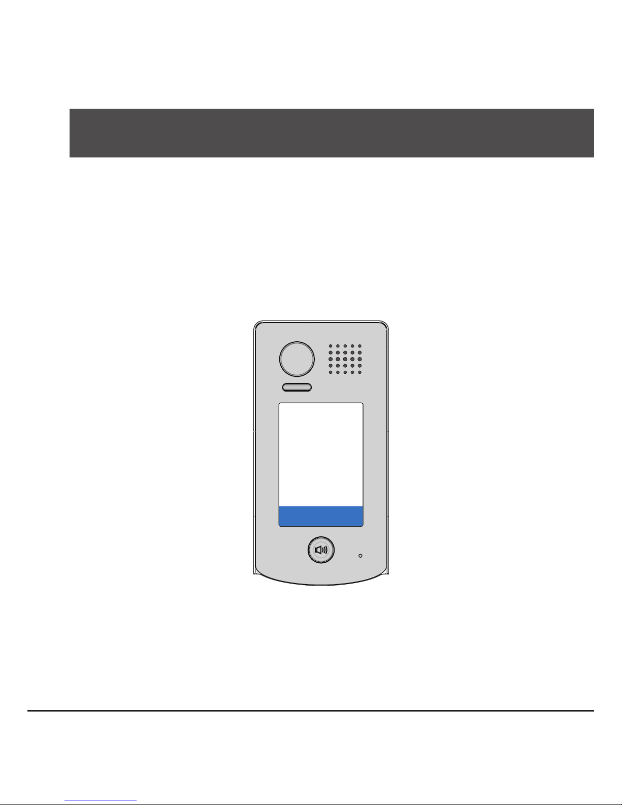
1.Parts and Functions
Rainy Cover
DT601/KP
1
4 5 6
98
0 #
7
2 3
*
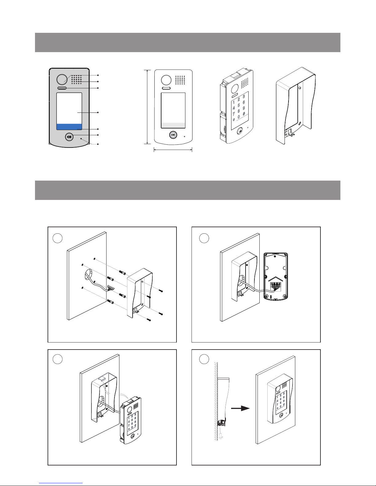
Camera Lens
Touch Sensitive
Digital Keypad
Speaker
Nameplate
Call Button
Microphone
93 mm
28 mm
182 mm
1
4 5 6
98
0 #
7
*
2 3
Night Light
2.Mounting
1 2
43
Drill holes in the wall to match the size of
screws and attach the rainy cover to the wall.
Attach the panel to the rainy cover Use the screwdriver and the screw
to fix the panel
Connect the cable correctly
DT601/KP Mounting
-2-
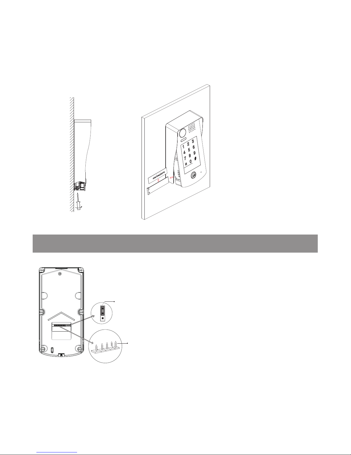
1 2 3
Lock Control Jumper
BUS
PL
S+
S-
Main Connect Port
3.Terminal Descriptions
Placing Name Label
Use a screwdriver to unscrew the screw, and cock the host , then Placing Name Label.
•
Lock Control Jumper:
To select the lock type.
•
Main Connect Port:
To connect the bus line and
the electronic locks.
•BUS: Connect to the bus line, no polarity.
• PL: External lock power input, connect to the power
positive(power +).
• S+: Lock power(+) output.
• S-: Lock power(-) output, connect to the power(-)
input of locks(only when using the camera to power
the locks, if using the external power supply for the
locks, the S- will not be connected).
-3-
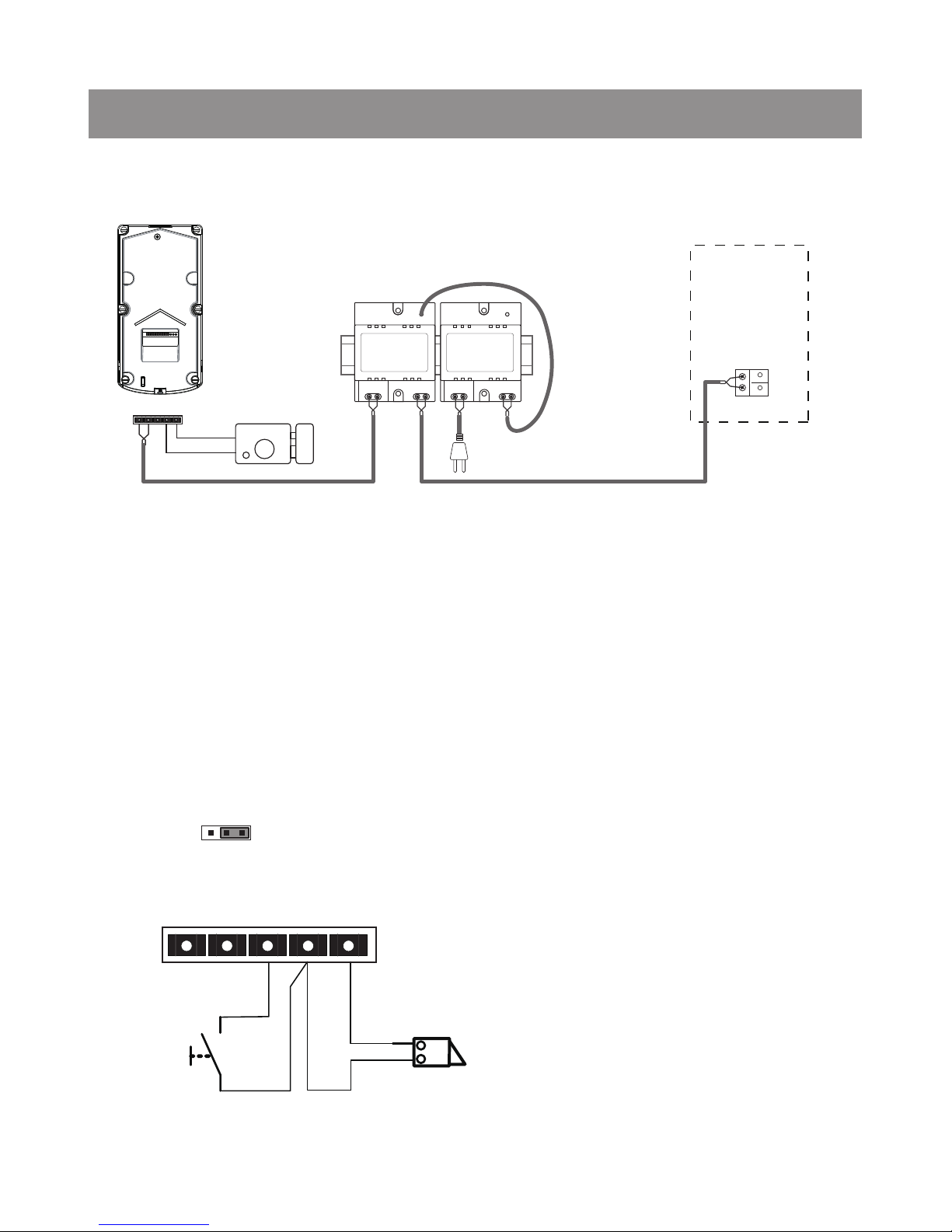
Basic Connection
4.System Wiring and Connections
-
+
AC~
monitor
DPS PS4
L1 L2 PL S+ S-
Electric Lock Connection
Door Lock Controlled with Internal Power
Note:
1. Electronic lock of Power-on-to-unlock type should be used.
2. The door lock is limited to 12V, and holding current must be less than 250mA.
3. The door lock control is not timed from Exit Button(EB).
4. The
Unlock Mode
Parameter of Monitor must be set to 0 (by default).
EB
*
LOCK
BUS PL S
+
S-
Jumper position in
Connect one lock
2-3
1 2 3

-4-
Unlock parameter setting(set in monitor)
Take off the Jumper
POWER
SUPPLY
BUS PL S+S-
Connect one lock
Note:
1.must connect DT601/KP correctly before setting.
2.the parameter will be saved in DT601/KP automatically,so you need only set on one monitor.
3.the above diagram is t for icon menu series monitors only, to text menu series monitors,please refer to
the corresponding user manual.
1.Touch item on main
menu page.
2.Touch the screen anywhere
and hold for 2s.
3.Touch Installer setup item
4.A digital keypad and setting
instructions will be showed.
Manual
Monitor
Monitor
Memory
Playback
Album
User Setup
09/30/2010 Thu.16:41
Close
Intercom
Multimedia
About
?
H/W : --- a1.3
S/W: V17.11.418.00
Local addr: --Unlock timing: --Video standard: UI-CODE: --MCM-VER.: --Updated: ---
Home
Installer
setup
Caliber
TouchScreen
Code Number:[----]
[0010]#:Remove all remote control
[0011]#:Add remote control
[8000]#:Set as master unit 0
[8001]#:Set as slaver unit 1
[8002]#:Set as slaver unit 2
[8003]#:Set as slaver unit 3
[8004]#:Set as guard unit
[8005]#:Set as not guard unit
[8006]#:Panel on as slaver unit called
[8007]#:Panel off as slaver unit called
[8008]#:Date format:MM/DD/YYYY
[8009]#:Date format:DD/MM/YYYY
[8010]#:Set lock mode to 0
[8011]#:Set lock mode to 1
[8021]~[8029]
#Set the lock time of 1~9s
Multi language settings:
---
1
4
7
8
0
9
6
5
2
3
Cancel
Installation settings:
Door Lock Controlled with Dry Contact
Note:
1. The external power supply must be used according
to the lock.
2. The inside relay contact is restricted to AC or DC
24V/1A.
3. The jumper must be taken off before connecting.
4. Setup the
Unlock Mode
of Monitor for different
lock types.
• Power-on-to-unlock type:Unlock Mode=0 (by
default)
• Power-off-to-unlock type:Unlock Mode=1
 Loading...