

Videotec PTH310, PTH311 Operating Instructions Manual

OPERATING INSTRUCTIONS
---------------------------------------------------------------------------------------------------------------------------------------------------------
MANUALE D’USO
---------------------------------------------------------------------------------------------------------------------------------------------------------
MANUEL D’INSTRUCTIONS
---------------------------------------------------------------------------------------------------------------------------------------------------------
BEDIENUNGSANWEISUNG
---------------------------------------------------------------------------------------------------------------------------------------------------------
РУКОВОДСТВО ПО ЭКСПЛУАТАЦИИ


OPERATING
INSTRUCTIONS


Pag. 1 MNVCPTH300_1541_EN
INDEX
PTH310 – PTH311 ..................................................................................................................................................................................... 1
INDEX ..................................................................................................................................................................................... 1
INTRODUCTION .................................................................................................................................................................... 2
Packing contents ........................................................................................................................................................................................ 2
Contents of this Manual .............................................................................................................................................................................. 2
Typographic conventions ............................................................................................................................................................................ 2
SAFETY RULES ..................................................................................................................................................................... 2
IDENTIFICATION DATA ........................................................................................................................................................ 3
DESCRIPTION OF PTH310 / PTH311 PAN & TILT MOTORS ............................................................................................. 3
Features ..................................................................................................................................................................................................... 3
Appliances compatible with PTH310 / PTH311 .......................................................................................................................................... 3
INSTALLATION ...................................................................................................................................................................... 4
Unpacking .................................................................................................................................................................................................. 4
Check of identification data ........................................................................................................................................................................ 4
ADJUSTMENT OF PTH310 / PTH311 PAN & TILT MOTORS ............................................................................................. 4
Adjustment of the potentiometer for PTH310P / PTH311P preset pan & tilt motor ..................................................................................... 5
CONNECTORS AND CONNECTIONS .................................................................................................................................. 6
Installation example .................................................................................................................................................................................... 6
Installation example .................................................................................................................................................................................... 6
Cables ........................................................................................................................................................................................................ 7
Pan & tilt connection to control units ........................................................................................................................................................... 7
Pan & tilt connection to CBZ keyboard ................................................................................................................................................... 8
Pan & tilt connection to DTMRX1/DTRX3 receiver ................................................................................................................................. 8
Preset connection to DTRX3 receiver (only PTH310P / PTH311P) ........................................................................................................ 8
SWITCHING ON AND OFF .................................................................................................................................................... 9
MAINTENANCE ..................................................................................................................................................................... 9
PROBLEM SOLUTION .......................................................................................................................................................... 9
SPECIFICATIONS ................................................................................................................................................................ 10
Mechanics ................................................................................................................................................................................................ 10
General ..................................................................................................................................................................................................... 10
Electric features ........................................................................................................................................................................................ 10
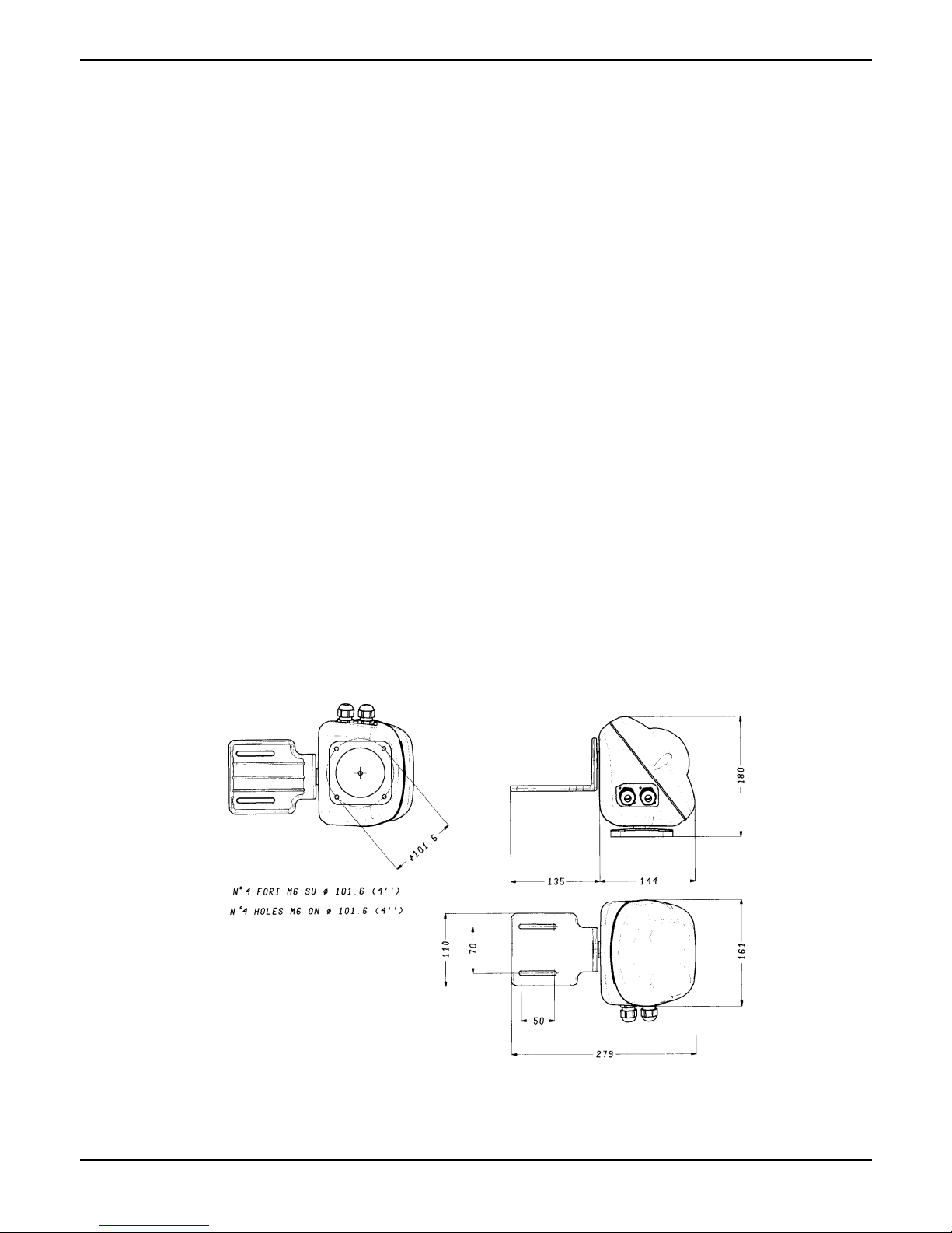
Dimensions ............................................................................................................................................................................................... 10
The manufacturer declines all responsibility for any damage caused by an improper use of the appliances mentioned
in this manual; furthermore, the manufacturer reserves the right to modify its contents without any prior notice.
The documentation contained in this manual has been collected with great care: the manufacturer, however, cannot
take any liability for its use. The same thing can be said for any person or company involved in the creation and
production of this manual.

Pag. 2 MNVCPTH300_1541_EN
Introduction
Packing contents
1 pan & tilt motor PTH310 / PTH311
1 bracket for camera
1 bag with bolts and screws
1 instruction manual
After the delivery, check that the packing is not damaged and shows no evident signs of falls or abrasions. Should this
be so, contact immediately the supplier.
Check that the contents correspond to the above-mentioned list of materials.
Contents of this Manual
This manual describes PTH310 / PTH311 pan & tilt motors, together with their specific procedures of installation,
configuration and use. Read this manual carefully, in particular the chapter concerning the safety rules, before
installing and using the pan & tilt motor.
Typographic conventions
Different graphic symbols are used in this manual, the meaning of which is here described:
Hazard of electric shock; disconnect the power supply before proceeding, if not otherwise specified.
The operation is very important for the correct working of the system: read carefully the procedure indicated,
and carry it out according to the required modalities.
Description of system features: read carefully to understand the following phases.
Safety rules
PTH310 / PTH311 pan & tilt motors comply with the normative laws in force at the time of editing of this
manual, concerning electric safety, electromagnetic compatibility and general requirements.
Anyway, in order to ensure the users (installer technician and operator), the following warnings are specified for
safety’s sake:
The appliance (and the complete system, which it belongs to) must be installed only by qualified technical staff
The appliance must be opened only by qualified technical staff. The tampering of the appliance may void the
guarantee terms.
Connect to a device corresponding to the specifications indicated on the data plate (see next chapter Identification
data)
Before any shifting or technical operations on the appliance, the cables connected to other appliances have been
removed
Do not use voltage cables showing wear or ageing, since they may seriously compromise the users’ safety
Do not use the appliance in the presence of inflammable substances
Do not allow children or people not familiar with the appliance to use it
Make sure the appliance is fixed in a solid and reliable way
The appliance is completely off-line only when the cables connected to other appliances have been removed
For after-sale service call only authorised technical staff
Keep this manual close to hand for any future reference

Pag. 3 MNVCPTH300_1541_EN
Identification data
On PTH310 / PTH311 pan & tilt motors there are two plates complying with EC specifications.
The first plate includes:
Model identification code (Extended bar code 3/9 )
Mains voltage (Volt)
Frequency (Hertz)
Power consumption (Watt)
The second plate shows the model serial number (Extended bar code 3/9)
When installing the appliance, check that the power supply specifications of the pan & tilt motor correspond to those
required. The use of improper appliances may seriously compromise the safety of the personnel and the installation.
Description of PTH310 / PTH311 pan & tilt motors
PTH310 / PTH311 unit is a vertical and horizontal pan & tilt motor, expressly projected for outdoor installations.
PTH310P / PTH311P models have all the features of PTH310 / PTH311 models, in addition to the PRESET.
Features
Horizontal movement (Pan): from 0 to 330°. Speed: 6° per second
Vertical movement (Tilt): from 0 to 360°. Speed: 3° per second
Construction in corrosion-proof die-cast aluminium
Completely sealed closing for indoor/outdoor operation
Operating temperature from -23°C to +60°C (from -10°F to 140°F)
PTH310 / PTH310P power supply: 230 V~
PTH311 / PTH311P power supply: 24 V~
PRESET for PTH310P / PTH311P models
The Autopan function is possible for limited periods of time
Appliances compatible with PTH310 / PTH311
The working of pan & Tilt motors ist guarrated only if connected to:
CBZ keyboard : Control keyboard for pan & tilt motors and zoom lenses
DTRX3 receiver driver: 17-function digital receiver, allowing the remote control of pan & tilt motors, wiper and
wash, and 4 auxiliary contacts. It can be individually addressed up to 999 units. It allows the management of max.
14 preset positions, which are recalled in the switching cycle by the patrol function.
DTMRX1 minireceiver driver: 11-function digital receiver, allowing the control of pan & tilt motors (horizontal and
vertical, zoom lenses, autopan). It can be individually addressed up to 64 units.
MICRODEC control mini receiver: Current Loop digital receiver allows the basic control of a 24V~ pan & tilt
motor and the 12VDC polarity inversion zoom lenses. Individually addressable up to 32 units.
Pag. 4 MNVCPTH300_1541_EN
Installation
The installation must be carried out only by qualified technical staff.
The following procedures must be carried out with power supply off, if not otherwise specified.
Unpacking
If the packing shows no relevant defects (due to falls or anomalous abrasions), check the material contained,
according to the list given at paragraph Packing contents chapter Introduction.
The packing materials can be completely recycled. The installer technician is required to dispose of them according to
the differentiated collecting modalities or ,anyway, according to the normative laws in force in the Country of use.
Check of identification data
Before installing the appliance, check that the material supplied corresponds to the specifications indicated on
the data plate, following the chapter Identification data. Do not carry out any modification or connections which are not
provided for in this manual: the use of improper appliances may seriously compromise the safety of the personnel and
the installation.
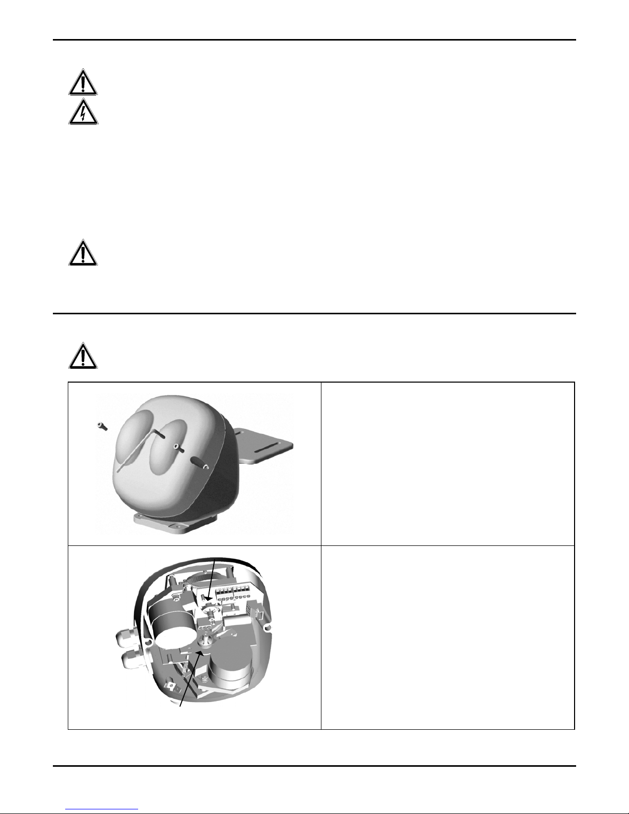
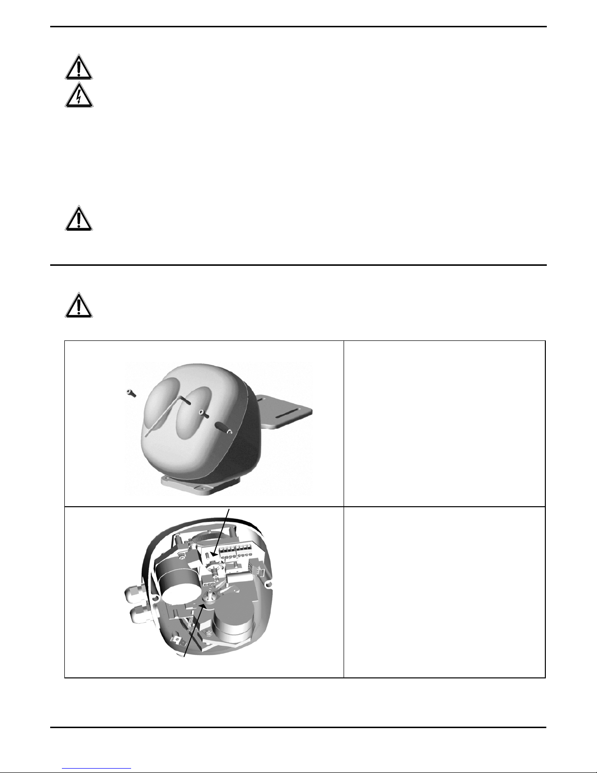
Adjustment of PTH310 / PTH311 pan & tilt motors
CAUTION: Do not position the pan & tilt motor manually, since this operation may seriously damage the gears.
Unscrew the cover screws and open the casing
Fig.1
Identify the limit switch cams for vertical and
horizontal stroke adjustment
Adjust the opening width of the limit switch cams
according to the angle wished (but symmetrically to
center of the two micro switches) by forcing them
slightly (no tools are necessary, it is a friction
movement)
Fig.2

Pag. 5 MNVCPTH300_1541_EN
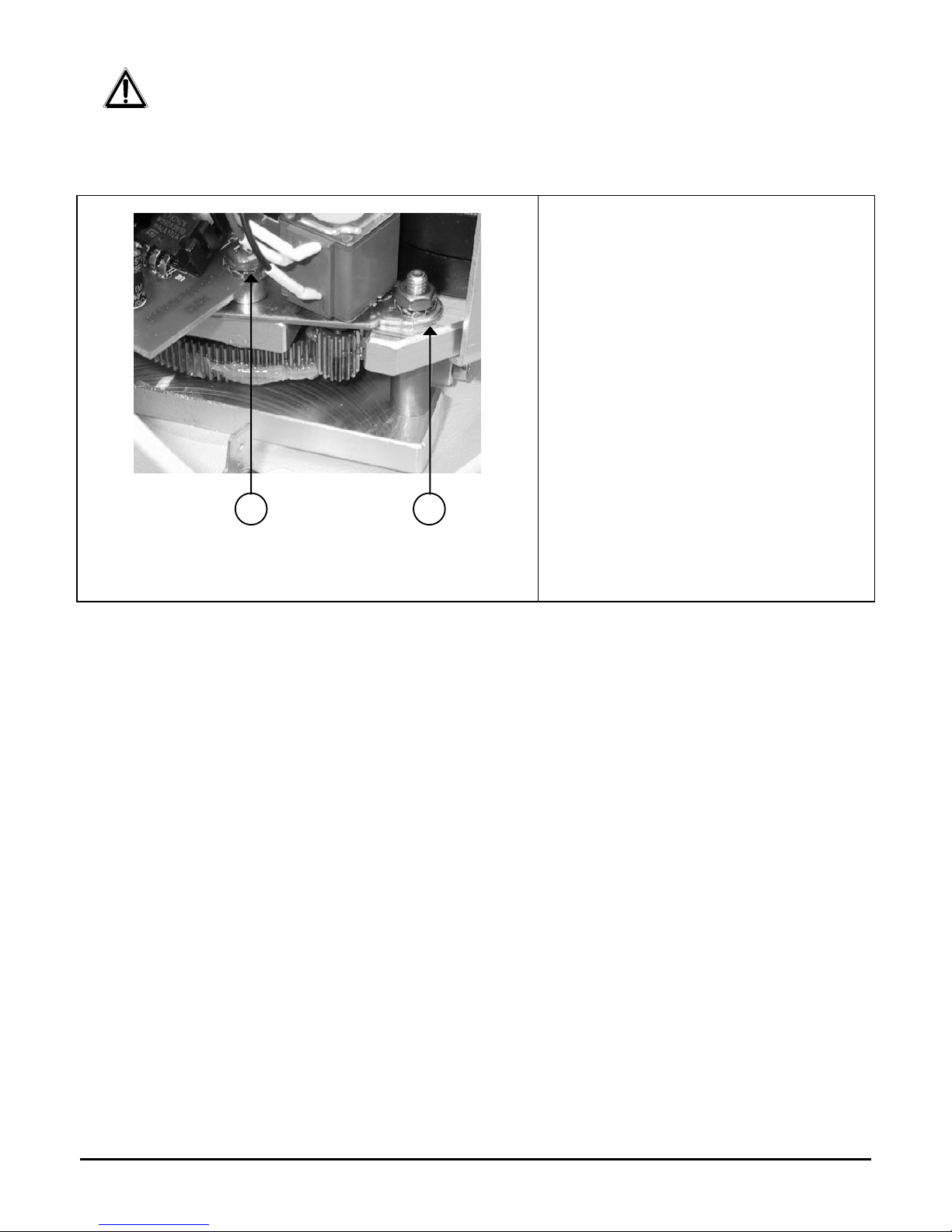
Adjustment of the potentiometer for PTH310P / PTH311P preset pan & tilt motor
This operation is very important for the correct working of the preset.
PTH310 / PTH311 Pan & Tilt motors are still set in our works, therefore this procedure is to be made only in case of
real necessity.
The following procedure has to be followed both for the potentiometer connected with the horizontal movement and for
the one connected with the vertical movement.
1. Disconnect the pan & tilt motor supply
2. Adjust the cams by means of a screwdriver
until their position is symmetric compared to
the end of stroke
3. Loosen the fixing screw “A” and the nut “B” of
the potentiometer holder bar of the horizontal
movement
4. Release the pinion from the gear
5. Place an Ohmmeter between the Vcc and
Pan clamps of the terminal strip J4 and turn
the potentiometer shaft, which is connected to
the horizontal movement, till reading the value
of about 1875 Ohm.
6. Replace the potentiometer gear
7. Lock the fixing screws “A” and the nut “B” of
the potentiometer holder bar of the horizontal
movement
8. Repeat the same operation for the vertical
movement till reading the potentiometer value
between Vcc and Tilt clamps of the terminal
strip J4.
A B
Pag. 6 MNVCPTH300_1541_EN
Connectors and connections
The installation must be carried out only by qualified technical staff: an improper connection of the peripheral
units may cause the keyboard to be isolated from the rest of the system.
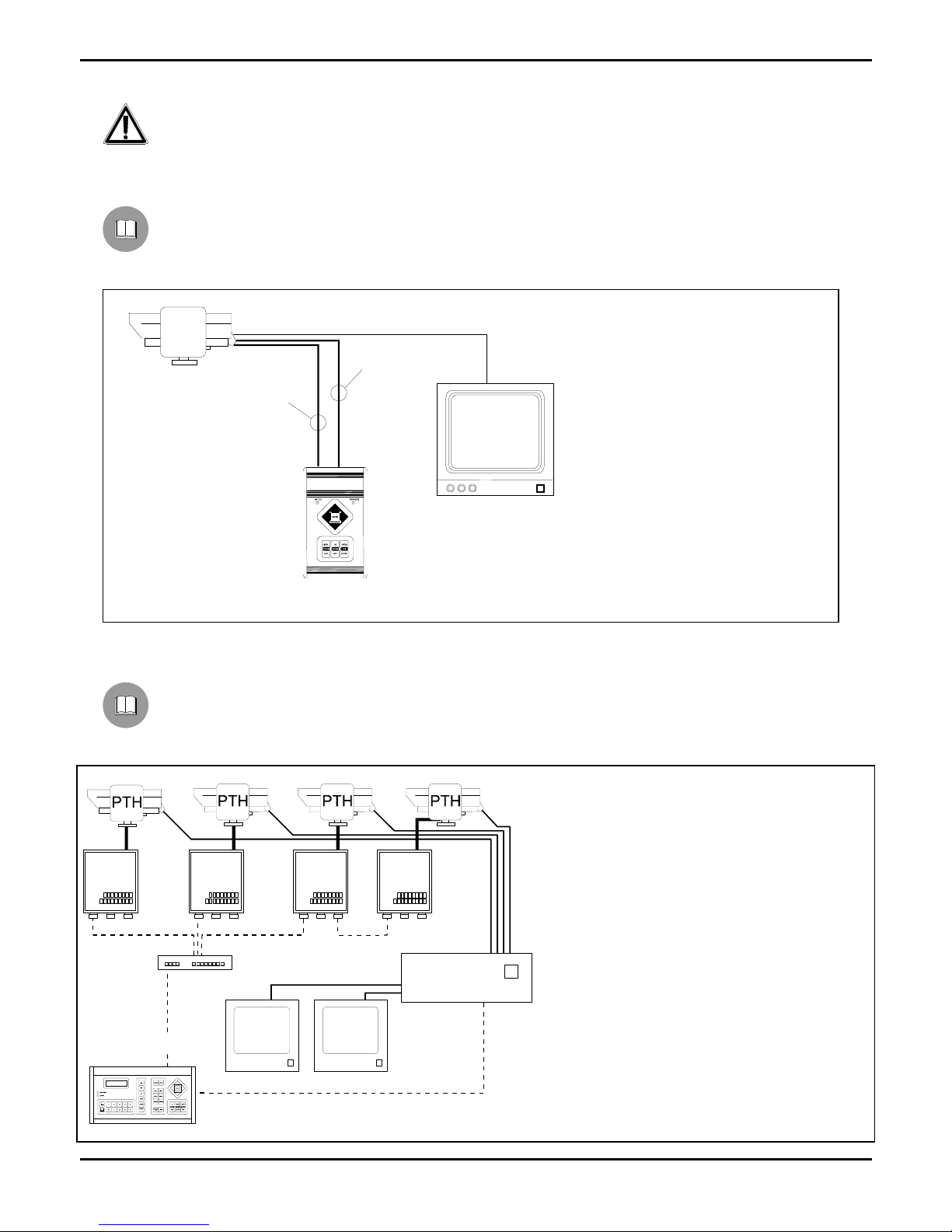
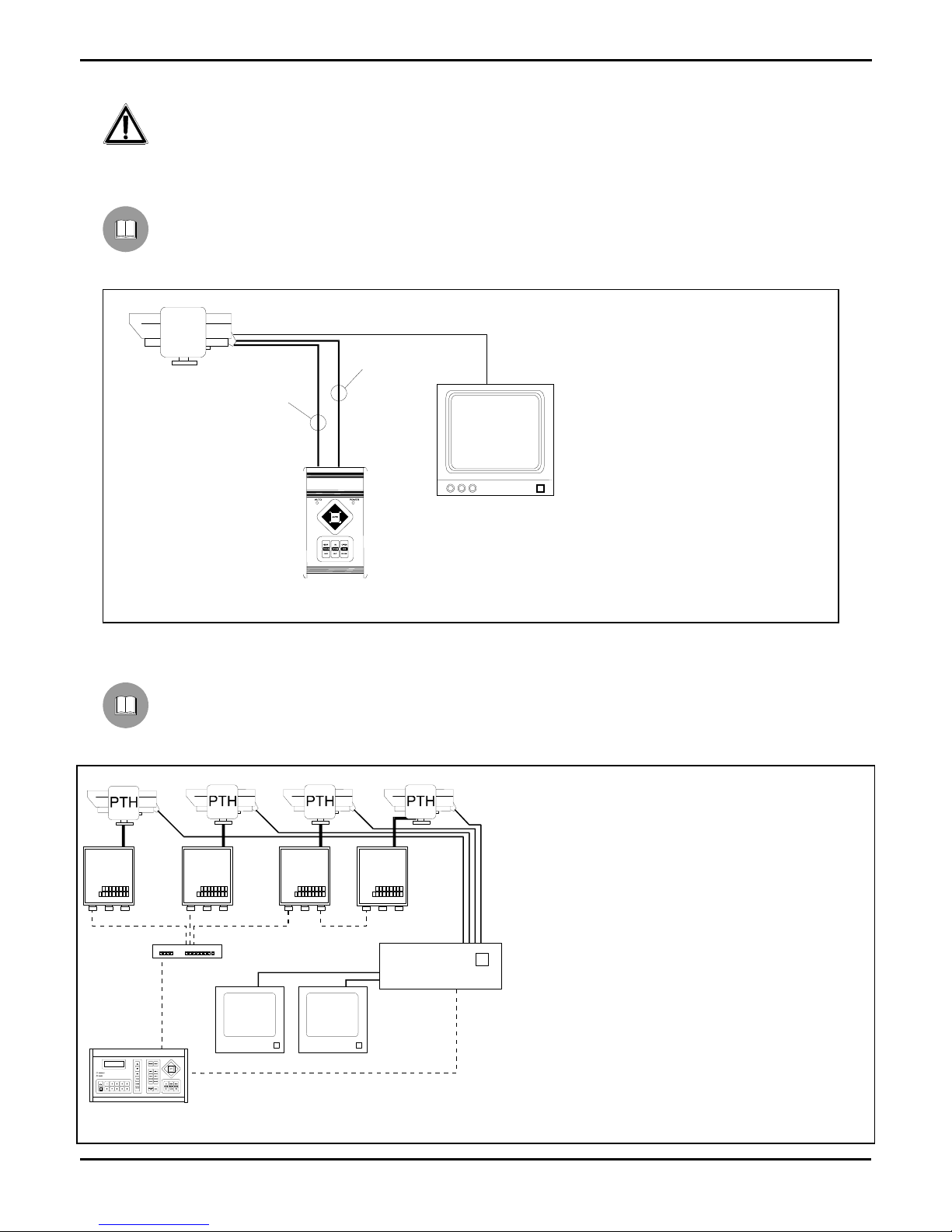
Installation example
Installation controlled by one operator with one monitor: the operator controls one pan & tilt motor and the
following telecamera functions FOCUS, ZOOM, DIAPHRAGM (IRIS):
MATERIAL USED
Control keyboard:
1 CBZ control keyboard
Video handling:
1 monitor
Telemetry handling:
1 PTH310 / PTH311
pan & tilt motor
1 motorized zoom lens
Installation example
One operator with more monitors, who controls a series of pan & tilt motors in mixed configuration (star and
cascade connection)
MATERIAL USED
Control keyboard:
1 DCS2 control keyboard
Video handling:
1 SW164OSM video switcher
2 monitors
4 telecameras
Telemetry handling:
1 DCMX serial data multiplexer
4 DTRX3 receivers
4 PTH310 / PTH311
pan & tilt motors
DTRX3
DTRX3
DTRX3
DTRX3
DCS2
SW164OSM
DCMX
CBZ
7 wires-cable for the
control of the P&T
head
P&T
6 wires-cable for
the control of the
lense
Pag. 7 MNVCPTH300_1541_EN
Cables
Different types of stroke have been used in the previous examples, in order to indicate cables with different
functions:
video cable:
RG 59 coaxial cable or equivalent cable
multipolar cable:
each control function of the positioning device is activated /deactivated by a relay positioned inside the receiver.
Fix the final numbers of wires according to the following directions:
7 wires for the motion of the positioning device: right, left, up, down, autopan, common, ground
6 wires for the control of polarity reversal lenses (zoom, focus, iris)
4 wires for the control of common wire lenses (zoom, focus, iris)
2 wires for the auxiliary device
Note: We recommend the use of different multipolar cables for high tension and low tension functions.
Minimum section area recommended: 0.56 mm.² (AWG 20) for high tension wires (positioning device)
0.34 mm.² (AWG 22) for low tension wires (lens, auxiliary device)
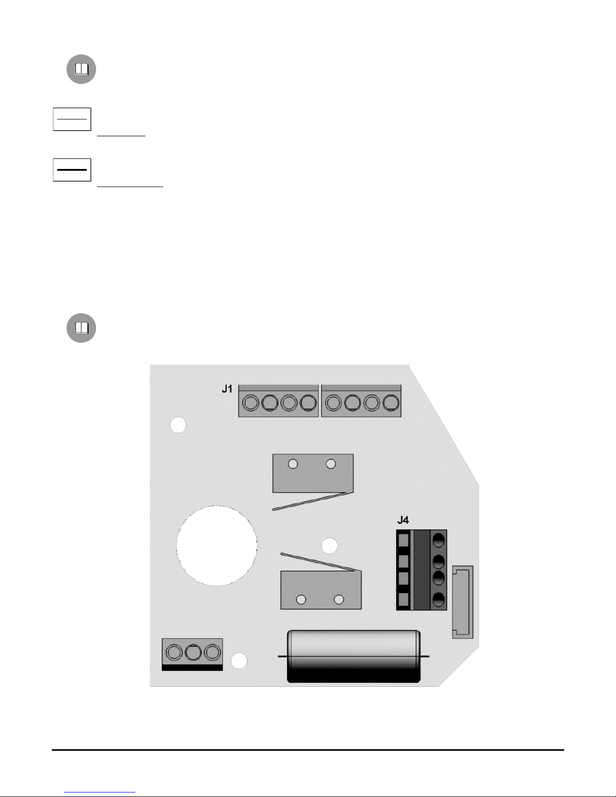
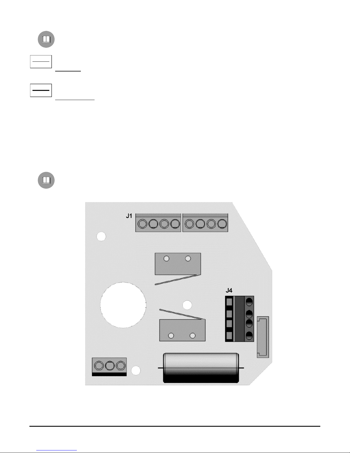
Pan & tilt connection to control units
In the following drawing, identify the terminal block J1 in the lower printed circuit for the pan & tilt connection to
the control units:
Pag. 8 MNVCPTH300_1541_EN
Pan & tilt connection to CBZ keyboard
WARNING: before the connection, make sure that the output voltage CBZ keyboard corresponds to pan & tilt
voltage (Refer to the identification data of the keyboard and of the pan & tilt motor).
Where to operate: J1 terminal block in the upper printed circuit of the pan & tilt motor (see drawing)
Adjustments : connect the wires from the keyboard to the pan & tilt motor according to the following table:
CBZ output wires J1 terminal block (Pan & Tilt)
WHITE Com
BROWN Down
YELLOW Up
GREY Right
PINK Left
GREEN Auto
YELLOW/GREEN
Pan & tilt connection to DTMRX1/DTRX3 receiver
WARNING: before the connection, make sure that the output voltage of the receiver corresponds to pan & tilt
voltage (Refer to the identification data of the pan & tilt motor and to DTMRX1/DTRX3 manual).
Where to operate: J1 terminal block in the upper printed circuit of the pan & tilt motor (see drawing), terminal block of
the receiver (see DTMRX1/ DTRX3 manual)
Adjustments: connect the terminal block J1 of the pan & tilt motor to that of the receiver according to the following
table
Connection to the receiver Terminal block J1 (Pan & Tilt)
COM Com
DOWN Down
UP Up
RIGH Right
LEFT Left
AUTO Auto
Preset connection to DTRX3 receiver (only PTH310P / PTH311P)
The following procedure has to be carried out only for PRESET pan & tilt motors and connected to DTRX3
receiver.
Where to operate : J4 terminal block in the upper printed circuit of the pan & tilt motor, preset terminal block (see
DTRX3 manual)
Adjustments: connect the J4 terminal block of the pan & tilt motor to the preset terminal block of DTRX3 according to
the following table:
Connection to DTRX3 Meaning Terminal block J4 (Pan & Tilt)
Vcc +5 Volt Vcc
Pan Horizontal Pan
Tilt Vertical Tilt
Gnd 0 Volt Gnd

Pag. 9 MNVCPTH300_1541_EN
Switching on and off
Before connecting the appliance:
check that the material supplied corresponds to the specifications indicated on the data plate, following the chapter
Identification data
check that PTH310 / PTH311 pan & tilt motor and the other components of the installation are closed
in order to
avoid direct contact with energized parts.
make sure that all the parts are fixed in a solid and reliable way
check that the electrical capacity and the connection cables will support the system power consumption
Maintenance
PTH310 / PTH311 pan & tilt motors do not need a special maintenance.
Make sure they always rest on a solid base, and that the power supply and connection cables do not hinder the
operator
Problem solution
Even if PTH310 / PTH311 pan & tilt motors are very easy to use, some problems may arise during installation,
configuration or use.
Problem Possible cause Remedy
The control keyboard or the
receiver are working, but the
pan & tilt motor does not
respond
Incorrect connections Check the connections between the pan &
tilt motor and the control unit
The voltage supplied by the
control unit is different from that
required by the pan & tilt motor
Check the identification data of the control
unit and of the pan & tilt motor
The pan & tilt motor
responds to the controls of
DTRX3 receiver but the
PRESET does not work
(only PTH310P / PTH311P)
Incorrect connections Check the connections between the pan &
tilt motor and DTRX3 receiver.
Pag. 10 MNVCPTH300_1541_EN
Specifications
Mechanics
Pan 0-330° horizontal plane movement
Speed 6° per second
Torque 6 Nm at specified voltage
Tilt 0-360° vertical plane movement
Speed 3° per second
Torque 6 Nm at specified voltage
Maximum load 12 Kg (26 lb) (balanced)
Protection IP 66
Potentiometer 5kOhm, multiple rotation (10 turns, max 1 million shaft rotations) - (only for PTH310P / PTH311P)
General
Construction Aluminium die-cast
Finish RAL9002 epoxy coat
Mounting pos. normal/reverse
Temperature from -23°C to +60°C (from -10°F to 140°F)
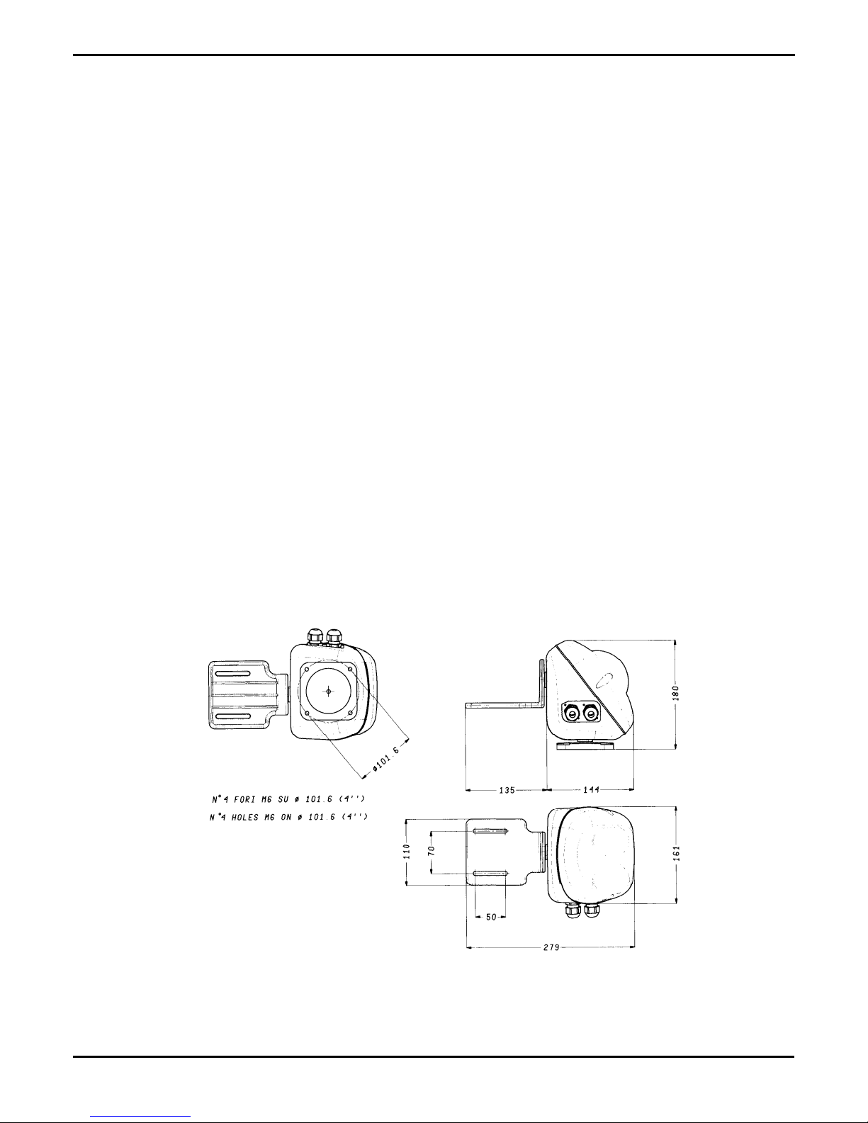
Dimensions 180x166x145 mm (
Weight 3,5 Kg (8 lb)
Cable diameter 10 mm
EAC certification
Electric features
Power Supply PTH310 / PTH310P 230 V~ 50/60 Hz 7+7 W
PTH311 / PTH311P 24 V~ 50/60 Hz 7+7 W
Wiring 7 cables 0.56mm.² (AWG 20) (Functions: left, right, up, down, common, autopan and earth).
4 cables 0.34mm.² (AWG 22) (Preset)
Dimensions

MANUALE
D’USO


Pag. 1 MNVCPTH300_1541_IT
INDICE
INDICE .................................................................................................................................................................................... 1
INTRODUZIONE ..................................................................................................................................................................... 2
Contenuto dell’imballo ................................................................................................................................................................................ 2
Cosa contiene questo manuale .................................................................................................................................................................. 2
Convenzioni tipografiche ............................................................................................................................................................................ 2
NORME DI SICUREZZA ........................................................................................................................................................ 2
DATI DI MARCATURA .......................................................................................................................................................... 3
DESCRIZIONE DEI BRANDEGGI PTH310 / PTH311........................................................................................................... 3
Caratteristiche ............................................................................................................................................................................................ 3
Apparecchi compatibili ................................................................................................................................................................................ 3
INSTALLAZIONE ................................................................................................................................................................... 4
Apertura dell’imballaggio ............................................................................................................................................................................ 4
Controllo della marcatura ........................................................................................................................................................................... 4
REGOLAZIONE DEI BRANDEGGI PTH310 / PTH311 ......................................................................................................... 4
Regolazione del potenziometro per il brandeggio con preset PTH310P / PTH311P .................................................................................. 5
CONNETTORI E COLLEGAMENTI ....................................................................................................................................... 6
Esempio di installazione ............................................................................................................................................................................. 6
Esempio di installazione ............................................................................................................................................................................. 6
Cavi ............................................................................................................................................................................................................ 7
Collegamento del brandeggio alle unità di comando .................................................................................................................................. 7
Collegamento del brandeggio alla tastiera CBZ ..................................................................................................................................... 8
Collegamento del brandeggio al ricevitore DTMRX1/DTRX3 ................................................................................................................. 8
Collegamento del Preset al ricevitore DTRX3 (solo PTH310P / PTH311P) ........................................................................................... 8
ACCENSIONE E SPEGNIMENTO ......................................................................................................................................... 9
MANUTENZIONE ................................................................................................................................................................... 9
RISOLUZIONE DI PROBLEMI ............................................................................................................................................... 9
CARATTERISTICHE TECNICHE ........................................................................................................................................ 10
Meccanica ................................................................................................................................................................................................ 10
Generali .................................................................................................................................................................................................... 10
Caratteristiche elettriche ........................................................................................................................................................................... 10
Dimensioni ................................................................................................................................................................................................ 10
Il produttore declina ogni responsabilità per eventuali danni derivanti da un uso improprio delle apparecchiature
menzionate in questo manuale; si riserva inoltre il diritto di modificarne il contenuto senza preavviso.
Ogni cura é stata posta nella raccolta e nella verifica della documentazione contenuta in questo manuale: tuttavia il
produttore non può assumersi alcuna responsabilità derivante dall’utilizzo della stessa. Lo stesso dicasi per ogni
persona o società coinvolta nella creazione e nella produzione di questo manuale.
Pag. 2 MNVCPTH300_1541_IT
Introduzione
Contenuto dell’imballo
1 brandeggio PTH310 / PTH311
1 staffa per supporto telecamera
1 sacchetto dotazione viteria
1 manuale d’uso
Alla consegna del prodotto verificare che l’imballo sia integro e non abbia segni evidenti di cadute o abrasioni. In caso
di evidenti segni di danno all’imballo contattare immediatamente il fornitore.
Controllare che il contenuto sia rispondente alla lista del materiale sopra indicata.
Cosa contiene questo manuale
In questo manuale sono descritti i brandeggi della serie PTH310 / PTH311, con le particolari procedure di
installazione, configurazione e utilizzo. E’ necessario leggere attentamente questo manuale, in particolar modo il
capitolo concernente le norme di sicurezza, prima di installare ed utilizzare il brandeggio.
Convenzioni tipografiche
Nel presente manuale si fa uso di diversi simboli grafici, il cui significato è riassunto di seguito:
Rischio di scariche elettriche; togliere l’alimentazione prima di procedere con le operazioni, se non é
espressamente indicato il contrario.
L’operazione é molto importante per il corretto funzionamento del sistema: si prega di leggere attentamente la
procedura indicata, ed eseguirla secondo le modalità previste.
Descrizione delle caratteristiche del sistema: si consiglia di leggere attentamente per comprendere le fasi
successive.
Norme di sicurezza
Il brandeggio PTH310 / PTH311 e’ conforme alle normative vigenti all’atto della pubblicazione del presente
manuale per quanto concerne la sicurezza elettrica, la compatibilità elettromagnetica ed i requisiti generali.
Si desidera tuttavia garantire gli utilizzatori (tecnico installatore e operatore) specificando alcune avvertenze per
operare nella massima sicurezza:
L’installazione dell’apparecchio (e dell’intero impianto di cui esso fa parte) deve essere effettuata da personale
tecnico adeguatamente qualificato
L’apparecchio deve essere aperto soltanto da personale tecnico qualificato. La manomissione dell’apparecchio fa
decadere i termini di garanzia
Collegare ad un dispositivo corrispondente come indicato sulle etichette di marcatura (vedere il successivo capitolo
Dati di marcatura)
Prima di spostare o effettuare interventi tecnici sull’apparecchio, disinserire i cavi di collegamento con altri
dispositivi
Non utilizzare cavi di tensione con segni di usura o invecchiamento, in quanto rappresentano un grave pericolo per
l’incolumità degli utilizzatori
Non utilizzare l’apparecchio in presenza di sostanze infiammabili
Non permettere l’uso dell’apparecchio a bambini o incapaci
Accertarsi che l’apparecchio sia fissato in maniera solida e affidabile
L’apparecchio si considera disattivato soltanto quando i cavi di collegamento con altri dispositivi sono stati rimossi
Per l’assistenza tecnica rivolgersi esclusivamente al personale tecnico autorizzato
Conservare con cura il presente manuale per ogni futura consultazione

Pag. 3 MNVCPTH300_1541_IT
Dati di marcatura
Sui brandeggi PTH310 / PTH311 sono riportate due etichette conformi alla marcatura CE.
La prima etichetta contiene:
Codice di identificazione del modello (Codice a barre Extended 3/9 )
Tensione di alimentazione (Volt)
Frequenza (Hertz)
Consumo (Watt)
La seconda etichetta indica il numero di serie del modello (codice a barre Extended 3/9)
All’atto dell’installazione controllare che le caratteristiche di alimentazione del brandeggio corrispondano a quelle
richieste. L’uso di apparecchi non idonei può portare a gravi pericoli per la sicurezza del personale e dell’impianto.
Descrizione dei brandeggi PTH310 / PTH311
L’unità PTH310 / PTH311 è un brandeggio verticale e orizzontale appositamente studiato per essere utilizzato
in ambienti esterni. Le versioni PTH310P/ PTH311P hanno tutte le caratteristiche dei modelli PTH310 / PTH311 più il
PRESET.
Caratteristiche
Movimento sul piano orizzontale (Pan): da 0 a 330°. Velocità: 6° al secondo
Movimento sul piano verticale (Tilt): da 0 a 360°. Velocità: 3° al secondo
Costruzione in fusione di alluminio con trattamento anticorrosione
Chiusura completamente sigillata per operare sia in ambiente interno che esterno
Temperatura di funzionamento da -23°C a +60°C (da -10°F a 140°F)
Alimentazione PTH310 /PTH310P: 230 V~
Alimentazione PTH311 / PTH311P: 24 V~
PRESET per le versioni PTH310P / PTH311P
È possibile utilizzare la funzione autopan per periodi limitati di tempo
Apparecchi compatibili
La funzionalita’ dei brandeggi e’ garantita solo se collegati a:
Tastiera CBZ: Tastiera di comando per brandeggi e ottiche
Ricevitore di comandi DTRX3: ricevitore digitale a 17 funzioni, consente il controllo a distanza di un brandeggio
motorizzato, di lavavetri e pompa, e di 4 contatti ausiliari. È indirizzabile singolarmente fino a 999 unità. Permette la
gestione di max 14 posizioni di preset, richiamabili in ciclata con la funzione patrol.
Miniricevitore di comandi DTMRX1: ricevitore digitale a 11 funzioni, consente il controllo di base di un
brandeggio motorizzato (orizzontale e verticale, ottiche, autopan). Indirizzabile singolarmente fino a 64 unità.
Microricevitore di comandi MICRODEC: ricevitore digitale in Current Loop, consente il controllo di base di un
brandeggio motorizzato in 24V~ e ottiche motorizzate a 12VDC ad inversione di polarità. Indirizzabile
singolarmente fino a 32 unità.
Pag. 4 MNVCPTH300_1541_IT
Installazione
La fase di installazione deve essere effettuata solo da personale tecnico qualificato.
Le seguenti procedure sono da effettuare in assenza di alimentazione, se non diversamente indicato.
Apertura dell’imballaggio
Se l’imballo non presenta evidenti difetti (dovuti a cadute o abrasioni anomale), procedere al controllo del materiale in
esso contenuto, secondo la lista fornita al paragrafo Contenuto dell’imballo al capitolo Introduzione.
I materiali d’imballo sono costituiti interamente da materiale riciclabile. Sarà cura del tecnico installatore smaltirli
secondo le modalità di raccolta differenziata o comunque secondo le norme vigenti nel Paese di utilizzo.
Controllo della marcatura
Prima di procedere con l’installazione controllare che il materiale fornito corrisponda alle specifiche richieste,
esaminando le etichette di marcatura, secondo quanto descritto al capitolo Dati di marcatura.
Non effettuare per nessun motivo alterazioni o collegamenti non previsti in questo manuale: l’uso di apparecchi non
idonei può portare a gravi pericoli per la sicurezza del personale e dell’impianto.
Regolazione dei brandeggi PTH310 / PTH311
ATTENZIONE: Non posizionare il brandeggio manualmente poichè questa operazione può danneggiare
seriamente gli ingranaggi.
Svitare le viti del coperchio e aprire la
scatola
Fig.1
Identificare le camme di finecorsa per la
regolazione della corsa verticale e di quella
orizzontale
Regolare l’ampiezza di apertura delle
camme dei finecorsa secondo l’angolo
desiderato (ma simmetricamente rispetto al
centro dei due microswitch) forzandole
leggermente (non servono attrezzi, il
movimento è a frizione)
Fig.2
Pag. 5 MNVCPTH300_1541_IT
Regolazione del potenziometro per il brandeggio con preset PTH310P / PTH311P
Questa funzione e’ molto importante per il corretto funzionamento del preset.
La seguente procedura deve essere eseguita sia per il potenziometro collegato al movimento orizzontale che per
quello collegato al movimento verticale.
Il brandeggio e’ gia’ regolato in fabbrica , dunque tale procedura dovra’ essere effettuata solo in caso di effettiva
necessita’.
1. Disconnettere l’alimentazione del brandeggio.
2. Regolare le camme con l’aiuto di un
cacciavite fino a renderne simmetrica la
posizione rispetto al fine corsa.
3. Allentare la vite di fissaggio A ed il dado B
della barra porta potenziometro del
movimento orizzontale
4. Disimpegnare il pignone dalla ruota dentata.
5. Posizionare un Ohmetro tra i morsetti Vcc e
Pan della morsettiera J4, girare l’alberino del
potenziometro collegato al movimento
orizzontale fino a leggere un valore di 1875
Ohm circa.
6. Riposizionare l’ingranaggio del
potenziometro.
7. Bloccare la vite di fissaggio A ed il dado B
della barra porta potenziometro del
movimento orizzontale
8. Ripetere la stessa operazione per il
movimento verticale leggendo il valore del
potenziometro tra i morsetti Vcc e Tilt della
morsettiera J4.
A B
Pag. 6 MNVCPTH300_1541_IT
Connettori e collegamenti
La procedura di installazione deve essere effettuata soltanto da personale tecnico qualificato: il collegamento
non corretto delle varie periferiche può comportare l’isolamento della tastiera dal resto del sistema.
Esempio di installazione
Impianto controllato da un operatore con un monitor: l’operatore controlla un brandeggio e le funzioni di
FUOCO (FOCUS), ZOOM, DIAFRAMMA (IRIS) della telecamera:
MATERIALE IMPIEGATO
Tastiera di controllo:
1 tastiera di controllo CBZ
Gestione del video:
1 monitor
Gestione della telemetria:
1 brandeggio PTH310 / PTH311
1 ottica motorizzata
Esempio di installazione
Un operatore con più monitor, con controllo di una serie di brandeggi in configurazione mista (a stella e in
cascata)
MATERIALE IMPIEGATO
Tastiera di controllo:
1 tastiera di controllo DCS2
Gestione del video:
1 commutatore video SW164OSM
2 monitor
4 telecamere
Gestione della telemetria:
1controllore di comunicazioni DCMX
4 ricevitori DTRX3
4 brandeggi PTH310 / PTH311
DTRX3
DTRX3
DTRX3
DTRX3
DCS2
SW164OSM
DCMX
CBZ
Cavo 7 fili
per il controllo del
brandeggio
P&T
Cavo 6 fili
per il controllo del
dell’ottica
Pag. 7 MNVCPTH300_1541_IT
Cavi
Negli schemi d’esempio sono stati utilizzati di versi tipi di tratto per indicare cavi di diversa funzione:
cavo video:
coassiale RG 59 o cavo equivalente.
cavo multipolare:
ogni funzione di controllo del brandeggio viene attivata / disattivata da un relè interno al ricevitore.
Stabilire il numero finale di cavi, seguendo le indicazioni seguenti:
7 fili per la movimentazione del brandeggio: destra, sinistra, alto, basso, autopan, comune, terra
6 fili di controllo per ottiche ad inversione di polarità (zoom, focus, iris)
4 fili di controllo per ottiche a filo comune (zoom, focus, iris)
2 fili per l’ ausiliare
Nota: è consigliato l’utilizzo di differenti cavi multipolari per le funzioni in bassa tensione ed in alta tensione.
Sezione minima consigliata: 0,56 mm.² (AWG 20) per fili in alta tensione (brandeggio)
0,34 mm.² (AWG 22) per fili in bassa tensione (ottica, ausiliare)
Collegamento del brandeggio alle unità di comando
Nella figura seguente identificare la morsettiera J1 per il collegamento del brandeggio alle unità di comando:

Pag. 8 MNVCPTH300_1541_IT
Collegamento del brandeggio alla tastiera CBZ
ATTENZIONE: prima di eseguire i collegamenti assicurarsi che la tensione in uscita dalla tastiera CBZ
corrisponda alla tensione del brandeggio (Fare riferimento ai dati di marcatura della tastiera e del brandeggio).
Dove Agire: morsettiera J1 sulla scheda superiore del brandeggio (vedi figura)
Impostazioni: collegare i fili provenienti dalla tastiera al brandeggio secondo la tabella seguente :
Fili in uscita da CBZ Collegamento al
brandeggio
BIANCO Com
MARRONE Down
GIALLO Up
GRIGIO Right
ROSA Left
VERDE Auto
GIALLO/VERDE
Collegamento del brandeggio al ricevitore DTMRX1/DTRX3
ATTENZIONE: prima di eseguire i collegamenti assicurarsi che la tensione in uscita dal ricevitore corrisponda
alla tensione del brandeggio (Fare riferimento ai dati di marcatura del brandeggio e al manuale DTMRX1/ DTRX3).
Dove Agire: morsettiera J1 sulla scheda superiore del brandeggio (vedi figura), morsettiera del ricevitore (vedi
manuale DTMRX1/DTRX3)
Impostazioni: collegare la morsettiera J1 del brandeggio a quella del ricevitore secondo la tabella seguente
Collegamento al ricevitore Morsetto J1 (brandeggio)
COM Com
DOWN Down
UP Up
RIGHT Right
LEFT Left
AUTO Auto
Collegamento del Preset al ricevitore DTRX3 (solo PTH310P / PTH311P)
La seguente procedura è da effettuare solo per i brandeggi con PRESET collegati al ricevitore DTRX3.
Dove Agire: morsettiera J4 sulla scheda superiore del brandeggio, morsettiera preset (vedi manuale DTRX3)
Impostazioni: collegare la morsettiera J4 in uscita dal brandeggio alla morsettiera preset del DTRX3 secondo la
tabella seguente
Collegamento sul DTRX3
Significato Morsetto J4 sul brandeggio
VCC +5 Volt Vcc
PAN Orizzontale Pan
TILT Verticale Tilt
GND 0 Volt Gnd

Pag. 9 MNVCPTH300_1541_IT
Accensione e spegnimento
Prima di fornire alimentazione:
controllare che il materiale fornito corrisponda alle specifiche richieste, esaminando le etichette di marcatura,
secondo quanto descritto al capitolo Descrizione della marcatura.
controllare che il brandeggio PTH310 / PTH311
e gli altri componenti dell’impianto siano chiusi e sia quindi
impossi- bile il contatto diretto con parti in tensione.
accertarsi che tutte le parti siano fissate in maniera solida ed affidabile
controllare che le fonti di alimentazione ed i cavi di collegamento siano in grado di sopportare il consumo del
sistema
Manutenzione
I brandeggi PTH310 / PTH311 non necessitano di particolare manutenzione.
Si raccomanda di fissarlo saldamente ad una una base solida, con i cavi di alimentazione e di collegamento in
posizione tale da non essere causa di intralcio all’operatore.
Risoluzione di problemi
I brandeggi PTH310 / PTH311 sono caratterizzati da una notevole facilità d’uso, ma cio’ nonostante possono
insorgere dei problemi sia in fase di installazione o durante l’uso.
Problema Possibile causa Intervento correttivo
La tastiera di comando o il
ricevitore funzionano, ma il
brandeggio non risponde
Collegamenti errati Controllare i collegamenti tra brandeggio e
unità di comando
La tensione fornita dall’unità di
comando non è quella richiesta
dal brandeggio
Controllare i dati di marcatura dell’unità di
comando e del brandeggio
Il brandeggio risponde ai
comandi del ricevitore
DTRX3 ma il PRESET non
funziona (solo PTH310P /
PTH311P)
Collegamenti errati Controllare i collegamenti tra brandeggio ed il
ricevitore DTRX3
Pag. 10 MNVCPTH300_1541_IT
Caratteristiche tecniche
Meccanica
Pan 0-330° movimento nel piano orizzontale
Velocità 6° al secondo
Coppia 6 Nm al voltaggio specificato
Tilt 0-360° movimento nel piano verticale
Velocità 3° al secondo
Coppia 6 Nm al voltaggio specificato
Carico massimo 12 Kg (26 lb) - (bilanciato)
Protezione IP 66
Potenziometro 5kOhm, multigiro (10 giri, max 1 milione di rotazioni dell'albero) - (solo versione PTH310P / PTH311P)
Generali
Costruzione Fusione di alluminio;
Finitura Verniciatura RAL9002 con polveri epossidiche
Posiz. montaggio normale/rovescia
Temperatura da -23°C a +60°C (da -10°F a 140°F)
Dimensioni 180x166x145 mm (L x H x P)
Peso 3.5 Kg (8 lb)
Diametro cavo 10 mm
Certificazione EAC
Caratteristiche elettriche
Alimentazione PTH310 / PTH310P 230 V~ 50/60 Hz 7+7 W
PTH311 / PTH311P 24 V~ 50/60 Hz 7+7 W
Cablaggio 7 fili
0,56 mm.² (AWG 20) (Funzioni: sinistra, destra, alto, basso, comune, autopan, Terra)
4 fili 0,34 mm.² (AWG 22) (Preset)
Dimensioni

MANUEL
D’INSTRUCTIONS


Pag. 1 MNVCPTH300_1541_FR
INDEX
INDEX ..................................................................................................................................................................................... 1
INTRODUCTION .................................................................................................................................................................... 2
Contenu de l’emballage .............................................................................................................................................................................. 2
Contenu de ce manuel ............................................................................................................................................................................... 2
Conventions typographiques ...................................................................................................................................................................... 2
NORMES DE SECURITE ....................................................................................................................................................... 2
CARACTERISTIQUES TECHNIQUES .................................................................................................................................. 3
DESCRIPTION DES TOURELLES PTH310 / PTH311 ......................................................................................................... 3
Caractéristiques.......................................................................................................................................................................................... 3
Appareils compatibles ................................................................................................................................................................................ 3
INSTALLATION ...................................................................................................................................................................... 4
Déballage ................................................................................................................................................................................................... 4
Contrôle des caractéristiques techniques ................................................................................................................................................... 4
REGLAGE DES TOURELLES PTH310 / PTH311 ................................................................................................................ 4
Réglage du potentiomètre pour la tourelle avec préselection PTH310P / PTH311P .................................................................................. 5
CONNECTEURS ET RACCORDEMENTS ............................................................................................................................ 6
Exemple d’installation ................................................................................................................................................................................. 6
Exemple d’installation ................................................................................................................................................................................. 6
Câbles ........................................................................................................................................................................................................ 7
Raccordement de la tourelle aux unités de commande .............................................................................................................................. 7
Raccordement de la tourelle au pupitre CBZ .......................................................................................................................................... 8
Raccordement de la tourelle au récepteur DTMRX1/DTRX3 ................................................................................................................. 8
Raccordement de la Préselection au récepteur DTRX3 (seulement PTH310P / PTH311P ) ................................................................. 8
ALLUMAGE ET COUPURE ................................................................................................................................................... 9
ENTRETIEN ............................................................................................................................................................................ 9
RESOLUTION DES PROBLEMES ........................................................................................................................................ 9
DONNEES TECHNIQUES ................................................................................................................................................... 10
Mécanique ................................................................................................................................................................................................ 10
Données générales .................................................................................................................................................................................. 10
Données électriques ................................................................................................................................................................................. 10
Dimensions ............................................................................................................................................................................................... 10
Le producteur décline toute responsabilité pour les dommages éventuels dus à une utilisation non appropriée des
appareils mentionnés dans ce manuel; on réserve en outre le droit d’en modifier le contenu sans préavis.
La documentation contenue dans ce manuel a été rassemblée et vérifiée avec le plus grand soin: cependant, le
producteur ne peut pas s’assumer aucune responsabilité dérivante de l’emploi de celle-là. La même chose vaut pour
chaque personne ou société impliquées dans la création et la production de ce manuel.
Pag. 2 MNVCPTH300_1541_FR
Introduction
Contenu de l’emballage
1 tourelle PTH310 / PTH311
1 support caméra
1 sachet de vis
1 manuel d’emploi
Lors de la livraison du produit, vérifier si l’emballage est correct et s’il n’a pas subi des signes évidents de chutes ou
de choc. Si l’emballage présente des signes évidents de dommage, contacter immédiatement le transporteur. Vérifier
que le contenu correspond à la liste du matériel indiqué ci-dessus.
Contenu de ce manuel
Dans ce manuel on décrit les tourelles de la série PTH310 / PTH311, et les procédures particulières d’installation,
configuration et emploi. Il est nécessaire de lire attentivement ce manuel, surtout le chapitre concernant les normes
de sécurité, avant d’installer et employer la tourelle.
Conventions typographiques
Dans ce manuel on emploie des symboles graphiques différents, dont le sens est résumé ci-dessous:
Risque de décharge électrique; couper l’alimentation avant de procéder avec toute opération, si le contraire
n’est pas expressément indiqué.
L’opération est très importante pour le fonctionnement correct du système: lire attentivement la procédure
indiquée, et l’exécuter suivant les modalités prévues.
Description des caractéristiques du système: lire attentivement pour comprendre les phases suivantes.
Normes de sécurité
La tourelle PTH310 / PTH311 est conforme aux normes en vigueur au moment de la publication de ce manuel
pour ce qui concerne la sécurité électrique, la compatibilité électromagnétique et les conditions requises générales.
On désire toutefois garantir les utilisateurs (technicien installateur et opérateur) en précisant certaines instructions
pour opérer en toute sécurité:
L’installation de l’appareil (et du système complet dont il fait partie) doit être effectuée par une personne qualifiée
du point de vue technique.
L’appareil doit être ouvert seulement par un personnel technique qualifié. L’altération de l’appareil fait déchoir les
termes de garantie
Raccorder à un appareil en suivant les indications des plaques des caractéristiques techniques (voir le chapitre
suivant Caractéristiques techniques)
Avant de déplacer ou effectuer des interventions techniques sur l’appareil, débrancher les câbles de raccordement
avec d’autres dispositifs.
Ne pas employer de câbles de tension avec signes d’usure ou vieillissement, parce qu’ils peuvent compromettre
sérieusement la sécurité des utilisateurs.
Ne pas employer l’appareil en présence de substances inflammables
Ne pas laisser des enfants ou des personnes non qualifiées utiliser l’appareil
Vérifier si l’appareil est fixé de façon solide et fiable
L’appareil est désactivé seulement quand les câbles de raccordement avec d’autres dispositifs ont été enlevés.
Pour le service après-vente s’adresser exclusivement à personnel technique autorisé.
Conserver soigneusement ce manuel pour toute consultation ultérieure
 Loading...