

Videotec NTW User Manual [en, de, fr, it]
NTW
Liquid-cooled housing for thermal cameras
EN
English - Instructions manual
IT
Italiano - Manuale di istruzioni
FR
Francais - Manuel d'instructions
DE
Deutsch - Bedienungslanleitung


NTW
Liquid-cooled housing for thermal cameras
EN
English - Instructions manual

Contents
ENGLISH
1 About this manual ........................................................................................................ 3
1.1 Typographical conventions ................................................................................................................................ 3
2 Notes on copyright and information on trademarks ................................................ 3
3 Safety rules ................................................................................................................... 3
4 Identification ................................................................................................................ 4
4.1 Product description and type designation ................................................................................................... 4
4.2 Product markings ...................................................................................................................................................4
5 Preparing the product for use ..................................................................................... 4
5.1 Contents and unpacking ..................................................................................................................................... 4
5.2 Safely disposing of packaging material ......................................................................................................... 4
6 Assembling and installing ........................................................................................... 5
6.1 Installation ................................................................................................................................................................ 5
6.1.1 Opening the housing ............................................................................................................................................................ 5
6.1.2 Installing the camera ............................................................................................................................................................5
6.1.3 Cooling circuit ......................................................................................................................................................................... 6
6.1.4 Circuit for front flange with air barrier ............................................................................................................................ 6
6.1.5 Installing the camera power supply kit ..........................................................................................................................7
6.1.6 Limits to use .............................................................................................................................................................................7
7 Maintaining and cleaning ............................................................................................ 7
7.1 Window cleaning .................................................................................................................................................... 7
8 Disposal of waste materials ......................................................................................... 7
9 Technical data ............................................................................................................... 8
9.1 General .......................................................................................................................................................................8
9.2 Mechanical ................................................................................................................................................................ 8
9.3 Electrical ....................................................................................................................................................................8
9.4 Environment .............................................................................................................................................................8
9.5 Compliance to ......................................................................................................................................................... 8
10 Technical drawings ..................................................................................................... 9

1 About this manual
Before installing and using this unit, please read this
manual carefully. Be sure to keep it handy for later
reference.
1.1 Typographical conventions
DANGER!
High level hazard.
Risk of electric shock. Disconnect the
power supply before proceeding with any
operation, unless indicated otherwise.
WARNING!
Medium level hazard.
This operation is very important for the
system to function properly. Please read
the procedure described very carefully and
carry it out as instructed.
INFO
Description of system specifications.
We recommend reading this part carefully
in order to understand the subsequent
stages.
2 Notes on copyright and information on trademarks
The quoted names of products or companies are
trademarks or registered trademarks.
3 Safety rules
The manufacturer declines all responsibility
for any damage caused by an improper use
of the appliances mentioned in this manual.
Furthermore, the manufacturer reserves
the right to modify its contents without any
prior notice. The documentation contained
in this manual has been collected with great
care, the manufacturer, however, cannot
take any liability for its use. The same thing
can be said for any person or company
involved in the creation and production of
this manual.
• The device must be installed only and exclusively
by qualified technical personnel.
• Before any technical work on the appliance,
disconnect the power supply.
• Do not use power supply cables that seem worn
or old.
• Never, under any circumstances, make any
changes or connections that are not shown in
this handbook: improper use of the appliance
can cause serious hazards, risking the safety of
personnel and of the installation.
• Use only original spare parts. Not original spare
parts could cause fire, electrical discharge or other
hazards.
• Before proceeding with installation check the
supplied material to make sure it corresponds
to the order specification by examining the
identification labels ("4.2 Product markings", page 4).
EN - English - Instructions manual
3

4 Identification
4.1 Product description and type designation
The solid construction of this housing makes it
suitable for heavy duty applications, such as the
surveillance of ovens, foundries and other high
temperature environments.
The NTW housing is entirely constructed from
electropolished stainless steel and consists of a
body with a double chamber for the circulation of a
EN - English - Instructions manual
cooling liquid or air. The housing is enclosed by two
thick flanges at either end and allows cables to pass
through by means of two PG13.5 cable glands on
the back flange. The front flange can be equipped
with tempered glass, IR glass or Vicor glass for higher
temperature.
A special version is available with IR-proof glass.
Two 1/2” GAS connectors allow for the cooling liquid
inflow/outflow.
The housing is equipped with a flange designed to
create an air barrier in front of the glass. This prevents
the formation of dust deposits and attenuates the
heat of the glass itself. With the supplied air barrier,
the NXFIGRU filter group is recommended, which
purifies the air drawn from a compressor.
4.2 Product markings
See the label attached to the outside of the package.
5 Preparing the product for use
Any change that is not expressly approved
by the manufacturer will invalidate the
guarantee.
5.1 Contents and unpacking
When the product is delivered, make sure that the
package is intact and that there are no signs that it
has been dropped or scratched.
If there are obvious signs of damage, contact the
supplier immediately.
Keep the packaging in case you need to send the
product for repairs.
Check the contents to make sure they correspond
with the list of materials as below:
• NTW housing
• Housing equipment:
• Allen wrench
• Spacers
• Screws and washers
• Screws for camera
• Instructions manual
5.2 Safely disposing of
packaging material
The packaging material can all be recycled. The
installer technician will be responsible for separating
the material for disposal, and in any case for
compliance with the legislation in force where the
device is to be used.
Bear in mind that if the material has to be returned
due to a fault, using the original packaging for its
transport is strongly recommended.
4
6 Assembling and installing
Only specialised personnel should be
allowed to assemble and install the device.
In the 230Vac powered configuration
it is necessary to insert a 1 0 unipolar
main switch (open contact distance d>3
mm) upstream on the power line. This
switch should be used to disconnect the
power supply before carrying out any
maintenance operation or before opening
the housing.
6.1 Installation
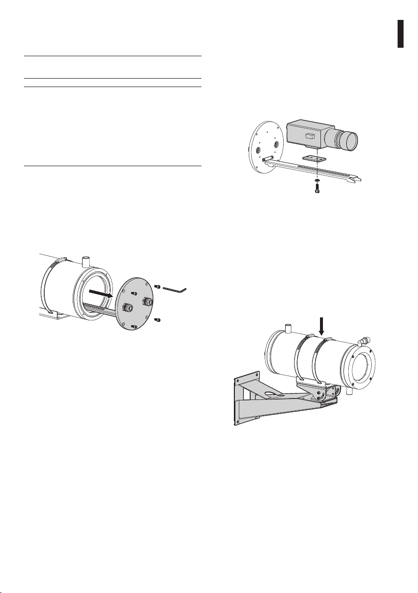
6.1.2 Installing the camera
This section describes how to install the camera
inside the housing.
Open the housing following the instructions given
above (Fig. 01, page 5).
Attach the camera to the internal slide with the 1/4”W
screw using the insulating bush. If necessary use the
spacers supplied and the appropriate 1/4”W screws
so as to position the camera and lens correctly.
EN - English - Instructions manual
6.1.1 Opening the housing
To open the housing, unscrew the 4 screws on the
back flange using the allen wrench supplied.
Slide out the rear cover plate of the housing, taking
care to leave the sealing washer in its seating.
Fig. 01
It will then be easy to gain access to the inside of
the housing without having to dismantle it from the
support bracket if already assembled.
Fig. 02
Make the correct electrical connections for the
camera and lens, passing the cables through the
cable glands. Make sure the latter are firmly locked
in place.
Close the housing by proceeding in the reverse order
to that described above (Fig. 01, page 5). Make sure the
sealing ring on the rear flange is correctly inserted in
its seating so as not to damage it.
Attach the housing to the bracket if this has not been
assembled already.
Fig. 03
5
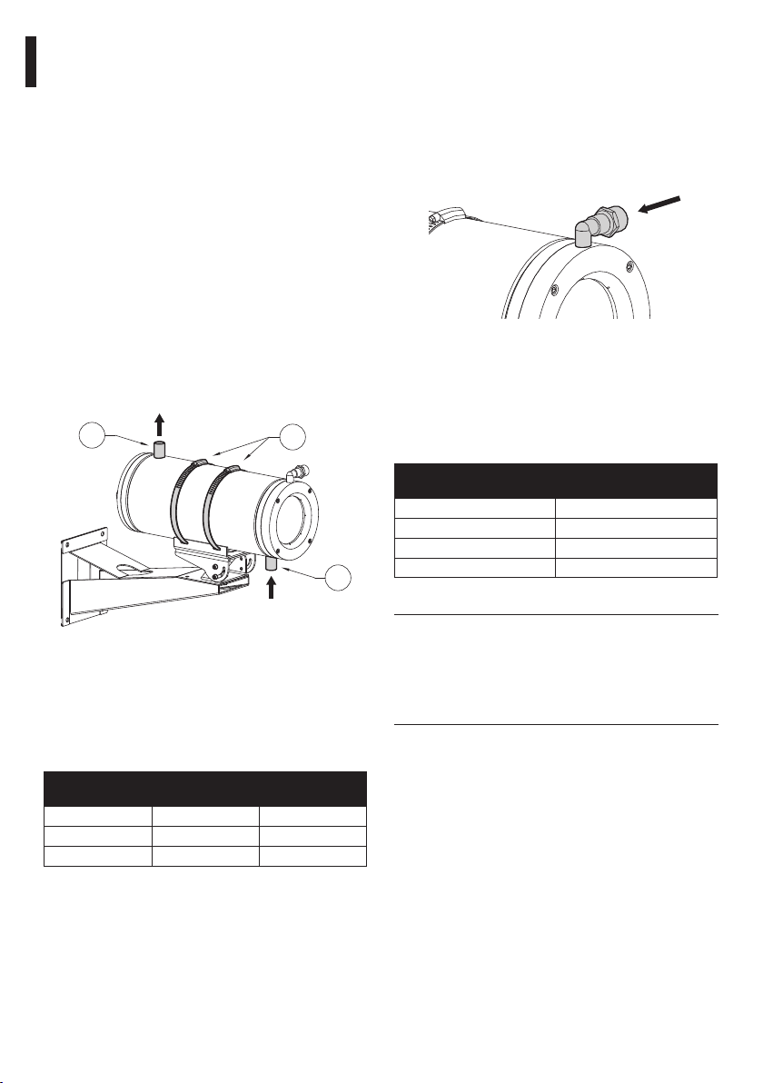
6.1.3 Cooling circuit
This section describes how to connect the housing
to the water cooling circuit and gives the results of
experimental data to determine the dimensions of
the latter. The housing is equipped with 1/2”Gas,
threaded, cooling water inlet and outlet connectors
with.
Use the connector on the housing body near
the front (01) as the cooling water inlet and the
connector near the back (02) as the cooling water
outlet.
This is only a general indication since the direction
EN - English - Instructions manual
from which the heat source originates and
installation constraints may make it necessary to
adapt the position of the water connectors and the
choice of input and output according to the specific
installation. This is possible because the housing
body can be rotated with respect to the support base
by adjusting the locking ties (03).
OUT water 1/2“Gas
02
IN water 1/2”Gas
Fig. 04
The following experimental data give the water flow
rate required to maintain a temperature below 45°C
inside the housing with an external temperature
Tmax =400 °C and refer to the use of water as cooling
liquid with an input temperature to the housing of
20°C.
T environment °C
200 2 32
300 2.2 41
400 6.5 44
Tab. 01
WATER FLOW
RATE L/MIN
03
01
T inside
housing °C
6.1.4 Circuit for front flange with air
barrier
This section describes how to connect the housing’s
front flange with air barrier. The air barrier flange is
fitted with a 1/4”Gas threaded connector and has a
1/2”Gas to 1/4”Gas reduction adapter. This connector
must be connected with the compressed air circuit
supplied by a compressor.
Fig. 05 IN air 1/4“Gas – 1/2“Gas.
We recommend using the optional filter unit
for cleaning the compressed air (NXFIGRU). The
maximum air pressure to be supplied to the air
barrier is 2.5 bar. The following experimental data
give the effective air consumption, for calculating the
size of the compressor:
COMPRES SED AIR
PRESSURE BAR
1 7
1.5 10
2 12
2.5 14
Tab. 02
Take care to use the correct camera power
supply kit, according to requirements
(available power supply and required
power supply output voltage). To assemble
the power supply option it is not necessary
to remove any pre-installed component.
AIR BARRIER
CONSUMP TION M3/H
6
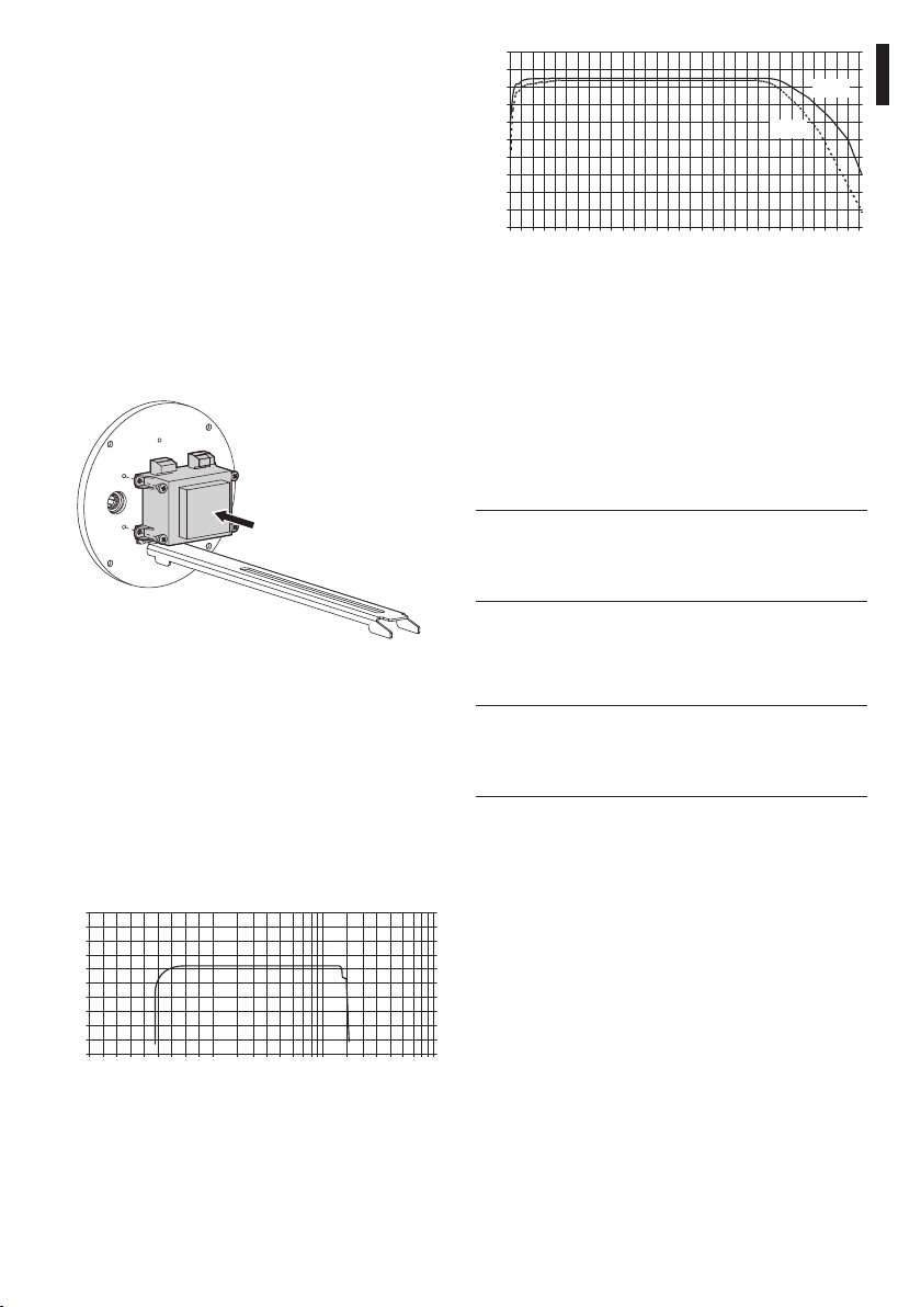
6.1.5 Installing the camera power supply kit
This section describes how to install the camera
power supply kit inside the housing. It is possible to
install a number of different types of power supply.
The input voltage may be 230Vac or 115Vac while the
output voltage may be 12Vdc or 24Vac, 400mA.
Open the housing following the instructions given
previously (Fig. 01, page 5).
Position the power supply to match the attachment
holes provided on the inner side of the rear flange of
the housing.
Attach the power supply to the rear plate of the
housing using the screws supplied with the power
supply kit.
100
90
80
70
60
50
40
30
20
Transmittance (%)
10
0
0,2
1
0,6
0,8
0,4
2
1,4
1,2
2,6
1,6
2,2
2,8
1,8
2,4
4
3
3,4
3,6
4,2
3,2
3,8
4,4
sp 1mm
sp 2mm
6
5
4,6
4,8
5,4
5,6
6,2
5,2
5,8
Wavelength (µm)
Fig. 08 Sapphire transmission curve. Field of
application from 0.75 tp 14¬μm.
7 Maintaining and cleaning
7.1 Window cleaning
Surface dirt should be rinsed away with water and
then the window cleaned with a neutral soap diluted
with water, or specific products for spectacle lens
cleaning. These should be applied with a soft cloth.
Avoid ethyl alcohol, solvents,hydrogenated
hydrocarbide, strong acid and alkali. Such
products may irreparably damage the
surface.
EN - English - Instructions manual
6,4
Fig. 06
Make the power supply-camera electrical
connections.
Close the housing, proceeding in the reverse order to
that described above, making sure the sealing ring on
the rear flange is correctly inserted in its seating so as
not to damage it (Fig. 01, page 5).
6.1.6 Limits to use
The housing has a front flange with an Ø80mm, ZincSelenium (4mm thick)or Sapphire glass (1mm thick).
100
80
60
40
20
Transmittance (%)
0
.4
.2
.2
.1
.5
.6
.8
.9
.7
Wavelength (µm)
Fig. 07 Zinc-Selenium transmission curve. Field
of application: from 7.5 to 14¬μm.
4.0
1.0
2.0
3.0
.5.0
30
20
10
40
50
8 Disposal of waste materials
This symbol mark and recycle system
are applied only to EU countries and not
applied to the countries in the other area of
the world.
Your product is designed and manufactured with
high quality materials and components which can be
recycled and reused.
This symbol means that electrical and electronic
equipment, at their end-of-life, should be disposed of
separately from your household waste.
Please dispose of this equipment at your local
Community waste collection or Recycling centre.
In the European Union there are separate collection
systems for used electrical and electronic products.
100
7

9 Technical data
9.1 General
Constructed from electropolished stainless steel
(Austenitic alloy stainless steel, corrosion and heat
resistant according to the following standards)
- UNI 6900-71: X 2 Cr Ni Mo 17 12
- AISI: 316
- DIN 17006: X 2 Cr Ni Mo 18 10
- N° WERKSTOFF: 1.4404
- AFNOR: Z2 CND 17-12
EN - English - Instructions manual
- BSI: 316 S 12
The screws utilised are in austenitic alloy stainless steel,
corrosion and heat resistant according to the following
standards
- UNI 6900: X 5 Cr Ni Mo 1712
- AISI: 316
- ISO quality: A4
- Resistance class ISO: 80
Supplied with instruction manual, desiccant bag,
accessories for camera and lens mounting
UNI: Ente Nazionale Italiano di Unificazione, AISI: American Iron and
Standard Institute, DIN: Deutsche Industrie Normen, AFNOR: Association
Française de Nor malisation, BSI: British Standard I nstitution, ISO:
International Organization for Standardization
9.2 Mechanical
2xPG13.5 cable glands in nickel-plated brass for external
connections
2x1/2”GAS connectors for liquid input / output
1x1/4”GAS connector for air barrier input
External body polishing
O-ring gaskets
9mm (0.35in) thick back flange
Window: internal Ø 60mm (2.4in), external Ø 80mm
(3.1in)
External dimensions: Ø 154mm (6.1in), length 375mm
(14.8in)
Internal usable dimensions (WxH): 78x78mm (3.1x 3.1in)
Interna usable length
NTW 345mm (13.6in)
Internal usable length with camera power supply
NTW 280mm (11.1in)
Unit Weight: 10.2kg / 22.5lb
ZiSe glass
4mm (0.16in) thick
Operating temperature 200°C (500°F)
Trasparency from 7.5 to 14 μm
Sapphire glass
1mm (0.04in) thick
Operating temperature 400°C (752°F)
Trasparency from 0.75 to 4.5 μm
Cooling liquid
Application example with incoming water at 20°C (68°F)
temperature:
- T environmental 200°C (392°F), water flow 2 l/min
(0.5US gal/min), T housing internal 32°C (89.6°F)
- T environmental 300°C (572°F), water flow 2.2 l/min
(0.6US gal/min),T housing internal 41°C (105.8°F)
- T environmental 400°C (752°F), water flow 6.5 l/min
(1.7US gal/min), T housing internal 44°C (111°F)
Cooling Air
Application example with incoming air at 17°C(62°F) and
an environmental temperature at 80°C(176°F)
- pressure 1 Bar -flow rate 10 m³/h, the internal
temperature is about 45°C(113°F)
- pressure 2 Bar -flow rate 15 m³/h, the internal
temperature is about 35°C(95°F)
Air filtering
Pressure air flow 0.3-2.5 Bar, filter 0.1 micron
Air Barrier
Max pressure 1Bar
9.3 Electrical
Camera power supply
- IN 230Vac - OUT 12Vdc, 50/60Hz, 400mA
- IN 230Vac - OUT 24Vac, 50/60Hz, 400mA
9.4 Environment
Indoor / Outdoor
9.5 Compliance to
CE according to EN61000-6-3, EN60065, EN50130-4
IP66 according to EN60529
8
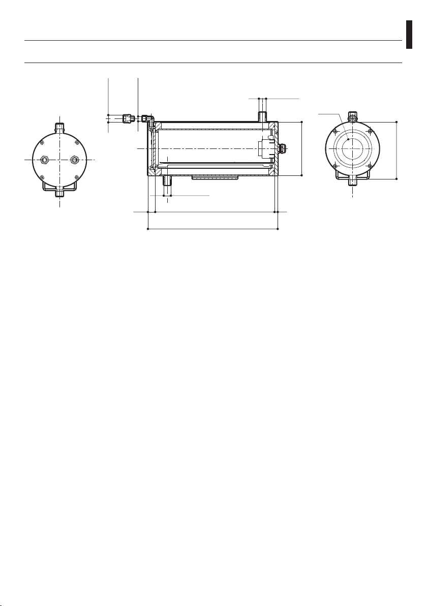
10 Technical drawings
The values are in millimeters.
Fig. 9 NTW
1/2" GAS
1/4" GAS
1/2" GAS
345
375
1/2" GAS
921
Ø 154
EN - English - Instructions manual
Ø 60
164
9

VIDEOTEC S.p.A.
www.videotec.com
Printed in Italy
MNVCNTW_0930_EN

NTW
Custodia raffreddata a liquido per telecamere termiche
IT
Italiano - Manuale di istruzioni

Sommario
ITALIANO
1 Informazioni sul presente manuale ............................................................................ 3
1.1 Convenzioni tipografiche .................................................................................................................................... 3
2 Note sul copyright e informazioni sui marchi commerciali ...................................... 3
3 Norme di sicurezza .......................................................................................................3
4 Identificazione .............................................................................................................. 4
4.1 Descrizione e designazione del prodotto ..................................................................................................... 4
4.2 Marcatura del prodotto ........................................................................................................................................ 4
5 Preparazione del prodotto per l'utilizzo .................................................................... 4
5.1 Contenuto e disimballaggio ............................................................................................................................... 4
5.2 Smaltimento in sicurezza dei materiali di imballaggio ............................................................................. 4
6 Assemblaggio e installazione ...................................................................................... 5
6.1 Installazione ............................................................................................................................................................. 5
6.1.1 Apertura della custodia........................................................................................................................................................ 5
6.1.2 Installazione della telecamera ........................................................................................................................................... 5
6.1.3 Circuito di raffreddamento .................................................................................................................................................6
6.1.4 Circuito flangia anteriore barriera d’aria ........................................................................................................................ 6
6.1.5 Installazione del kit alimentatore per telecamera ...................................................................................................... 7
6.1.6 Limiti di utilizzo ....................................................................................................................................................................... 7
7 Manutenzione e pulizia................................................................................................ 7
7.1 Pulizia del vetro ....................................................................................................................................................... 7
8 Smaltimento dei rifiuti ................................................................................................. 7
9 Dati tecnici .................................................................................................................... 8
9.1 Generale.....................................................................................................................................................................8
9.2 Meccanica ................................................................................................................................................................. 8
9.3 Elettrico ...................................................................................................................................................................... 8
9.4 Ambiente ................................................................................................................................................................... 8
9.5 Conformità ................................................................................................................................................................ 8
10 Disegni tecnici ............................................................................................................ 9
 Loading...