

Videotec GEKO IRN User Manual [en, de, fr, it]
GEKO IRN
LED illuminator
EN
English - Instructions manual
IT
Italiano - Manuale di istruzioni
FR
Français - Manuel d’instructions
DE
Deutsch - Bedienungslanleitung


GEKO IRN
LED illuminator
EN
English - Instructions manual

Contents
ENGLISH
1 About this manual ......................................................................................................... 3
1.1 Typographical conventions .................................................................................................................................. 3
2 Notes on copyright and information on trademarks ..................................................3
3 Safety rules..................................................................................................................... 3
4 Identication .................................................................................................................. 4
4.1 Product description and type designation..................................................................................................... 4
4.2 Product markings .................................................................................................................................................... 4
5 Declaration of conformity to product standards ........................................................ 4
6 Preparing the product for use ...................................................................................... 4
6.1 Unpacking and contents ....................................................................................................................................... 4
6.1.1 Unpacking .................................................................................................................................................................................. 4
6.1.2 Contents ......................................................................................................................................................................................4
6.2 Preparatory work before installation ................................................................................................................ 4
6.3 Safely disposing of packaging material ........................................................................................................... 5
7 Assembling and installing ............................................................................................ 5
7.1 Installation .................................................................................................................................................................. 5
7.1.1 Installation of wall-mounted illuminator ........................................................................................................................ 5
7.1.2 24Vac and 12/24Vdc wiring version ..................................................................................................................................6
7.1.2.1 24Vac and 12/24Vdc version power supply cable ............................................................................................................................6
7.1.2.2 Telemetry control cable .............................................................................................................................................................................. 6
7.1.3 90/240Vac wiring version ..................................................................................................................................................... 7
7.1.3.1 90/240Vac version power supply cable ................................................................................................................................................ 7
7.1.3.2 Telemetry control cable .............................................................................................................................................................................. 7
7.1.4 Maximum cable length ......................................................................................................................................................... 8
7.1.5 Adjusting the activation threshold ................................................................................................................................... 8
7.1.5.1 Photocell sensitivity ..................................................................................................................................................................................... 8
7.1.5.2 Disabling the photocell .............................................................................................................................................................................. 9
7.1.6 Adjusting the power of the infrared illuminators ........................................................................................................ 9
7.2 Operational test ......................................................................................................................................................10
7.2.1 Checking the power supply ...............................................................................................................................................10
7.2.2 Checking the photocell’s operation ................................................................................................................................10
8 Disposal of waste materials ........................................................................................ 10
9 Technical data .............................................................................................................. 10
9.1 General ......................................................................................................................................................................10
9.2 Mechanical ............................................................................................................................................................... 10
9.3 Electrical .................................................................................................................................................................... 10
9.4 Illuminators .............................................................................................................................................................. 10
9.5 Environment ............................................................................................................................................................10
9.6 Certications ...........................................................................................................................................................10
10 Technical drawings .................................................................................................... 11
1 About this manual
Before installing and using this unit, please read this
manual carefully. Be sure to keep it handy for later
reference.
1.1 Typographical conventions
DANGER!
High level hazard.
Risk of electric shock. Disconnect the
power supply before proceeding with any
operation, unless indicated otherwise.
DANGER!
Hot surface.
Avoid contact. Surfaces are hot and may
cause personal injury if touched.
WARNING!
Medium level hazard.
This operation is very important for the
system to function properly. Please read
the procedure described very carefully and
carry it out as instructed.
INFO
Description of system specications.
We recommend reading this part carefully
in order to understand the subsequent
stages.
2 Notes on copyright and information on trademarks
The quoted names of products or companies are
trademarks or registered trademarks.
3 Safety rules
During normal operation the surface of the
illuminator can reach high temperatures.
Do not, therefore, allow direct contact
and position the appliance where it is
inaccessible to unauthorised persons.
Before touching switch o the illuminator
and allow to cool for a minimum period of
10 minutes.
Do not stare directly into the lamp at a
distance of less than 1.7m.
The manufacturer declines all responsibility
for any damage caused by an improper use
of the appliances mentioned in this manual.
Furthermore, the manufacturer reserves
the right to modify its contents without any
prior notice. The documentation contained
in this manual has been collected with great
care, the manufacturer, however, cannot
take any liability for its use. The same thing
can be said for any person or company
involved in the creation and production of
this manual.
• The device must be installed only and exclusively
by qualied technical personnel.
• Before any technical work on the appliance,
disconnect the power supply.
• Do not use power supply cables that seem worn
or old.
• Never, under any circumstances, make any
changes or connections that are not shown in
this handbook: improper use of the appliance
can cause serious hazards, risking the safety of
personnel and of the installation.
• Use only original spare parts. Non-original spare
parts could cause re, electrical discharge or other
hazards.
• Before proceeding with installation check the
supplied material to make sure it corresponds
to the order specication by examining the
identication labels (4.2 Product markings, page 4).
Instructions manual - English - EN
3
4 Identification
4.1 Product description and type designation
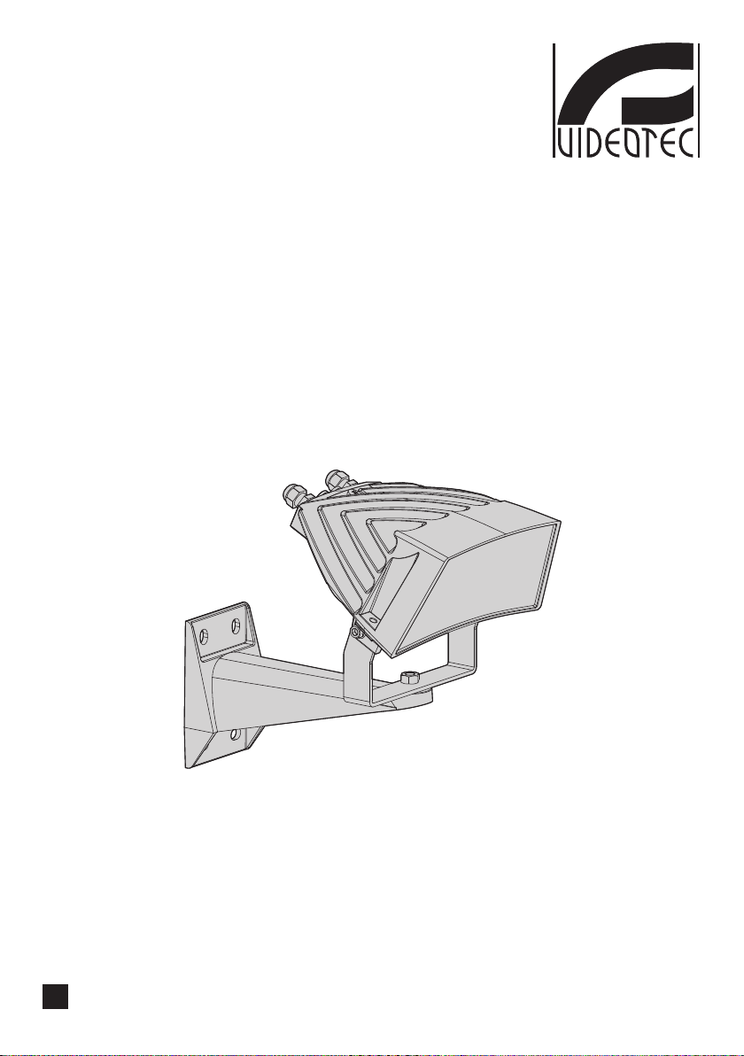
State of the art illuminator, which provides
high reliability and excellent image quality. The
GEKO lights the entire scene evenly, eliminating
hotspots and underexposures, for unbeatable
night-time images and secure surveillance of the
area. The high eciency heat sink body ensures
maximum LED durability and protection against
over-temperatures, whereas the front glass, made
EN - English - Instructions manual
of special technopolymer, provides high infrared
transmittance. The GEKO illuminators are protected
against electrostatic discharges.
The illuminator is available in versions 24Vac/1224Vdc or 90-240Vac with integrated power supply.
GEKO is supplied with a wall-mount bracket that
rotates horizontally and vertically.
4.2 Product markings
See the label attached to the outside of the package.
5 Declaration of conformity to product standards
• Electrical safety: EN60598
• Photobiological safety of lamps and lamp systems:
EN62471
• Electromagnetic compatibility: EN55022, Class A
• Immunity: EN50130-4
• FCC Part 15, Class A
6 Preparing the product for use
Any change that is not expressly approved
by the manufacturer will invalidate the
guarantee.
6.1 Unpacking and contents
6.1.1 Unpacking
When the product is delivered, make sure that the
package is intact and that there are no signs that it
has been dropped or scratched.
If there are obvious signs of damage, contact the
supplier immediately.
Keep the packaging in case you need to send the
product for repairs.
6.1.2 Contents
Check the contents to make sure they correspond
with the list of materials as below:
• GEKO illuminator with bracket
• Wall-fastening bracket
• Instructions manual
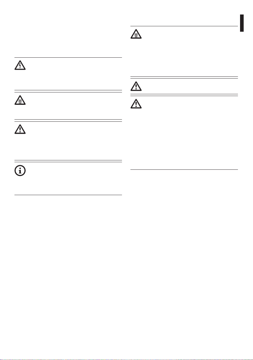
6.2 Preparatory work before
installation
Fasten the top bracket (01) to the lamp using the
screws and washers (02) supplied.
02
Fig. 1
4
02
01
6.3 Safely disposing of packaging material
The packaging material can all be recycled. The
installer technician will be responsible for separating
the material for disposal, and in any case for
compliance with the legislation in force where the
device is to be used.
Bear in mind that if the material has to be returned
due to a fault, using the original packaging for its
transport is strongly recommended.
7 Assembling and installing
During normal operation the surface of the
illuminator can reach high temperatures.
Do not, therefore, allow direct contact
and position the appliance where it is
inaccessible to unauthorised persons.
Before touching switch o the illuminator
and allow to cool for a minimum period of
10 minutes.
Do not stare directly into the lamp at a
distance of less than 1.7m.
Only specialised personnel should be
allowed to assemble and install the device.
7.1 Installation
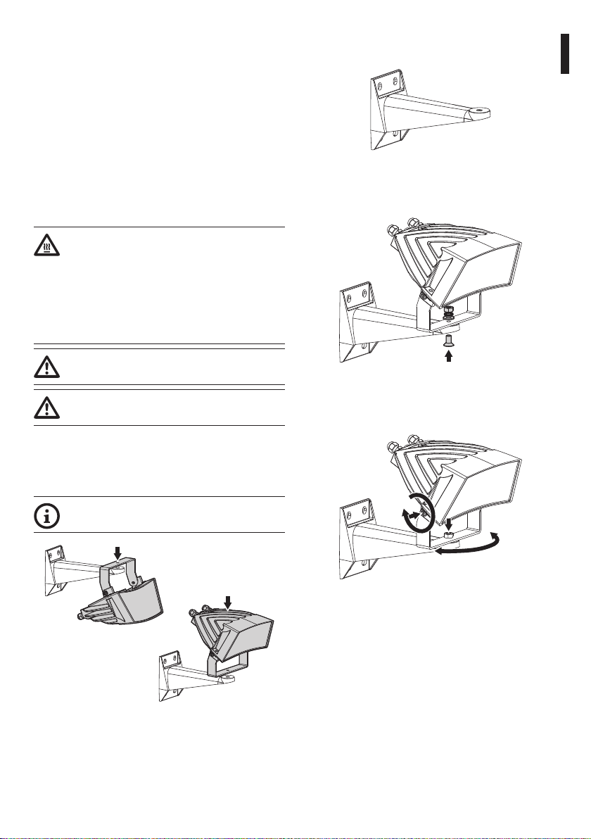
Fasten the bracket as shown in the gure. Drive the
wall screws in tight.
Instructions manual - English - EN
Fig. 3
Fasten the illuminator, complete with its bracket,
using the screw, the nut and the washer supplied.
Fig. 4
Set the illuminator’s vertical and horizontal
inclination by adjusting the two fastening screws.
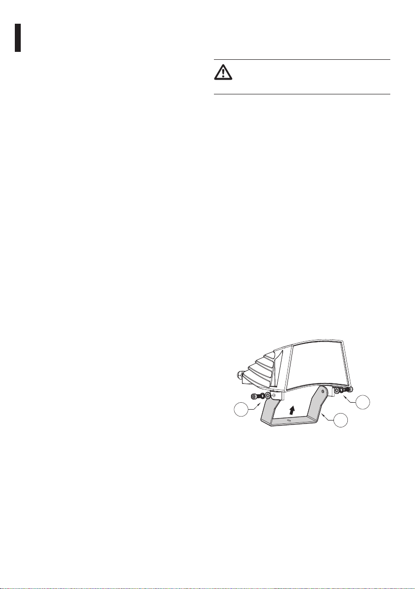
7.1.1 Installation of wall-mounted illuminator
The illuminator’s position can be decided at
the time of installation.
Fig. 2
Fig. 5
Check the resulting illumination range on the screen.
Tighten all the screws.
5
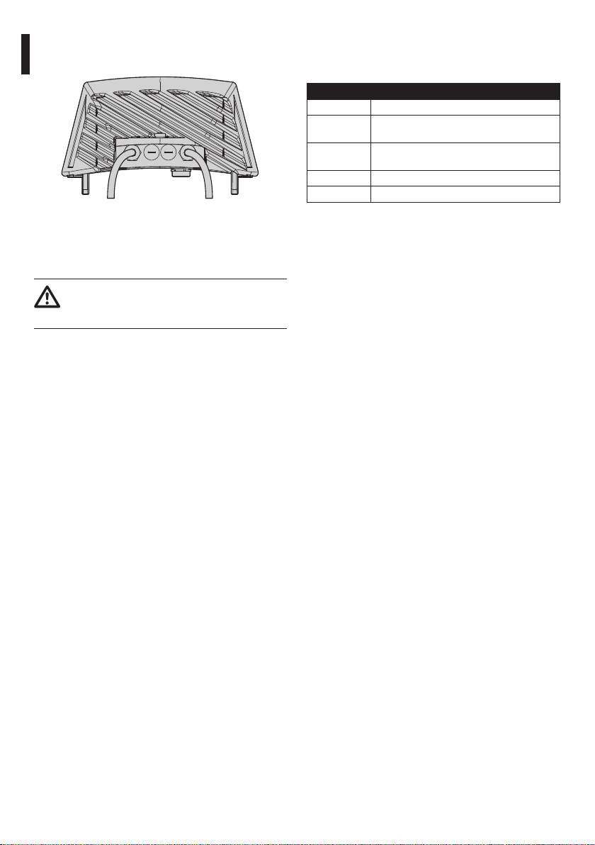
7.1.2 24Vac and 12/24Vdc wiring version
EN - English - Instructions manual
Fig. 6
7.1.2.1 24Vac and 12/24Vdc version power supply cable
The illuminator is provided with a 2m power cable.
Blue and brown power cables: Connect the two
poles to the supply (24Vac, 50/60Hz or 12-24Vdc). In
case of continuous current power supply, polarity is
irrelevant.
For maximum distances and recommended cable
sections, refer to the relative paragraph.
Control cable Power supply
The device is Class III. Provide power
supply using a safety transformer or a SELV
continuous current power supply.
7.1.2.2 Telemetry control cable
The product is equipped with a control cable to
manage one input contact and one output contact.
COLORS AND FEATURES OF THE CONTROL CABLE
Cable color Function
Red Input for activation by means of a volt free
relay contact
Green Input for activation by means of a volt free
relay contact
White Clean contact output (Follow)
Black Clean contact output (Follow)
Tab. 1
Input contact: It allows a remote activation of the
illuminator by means of a clean contact placed
between the ends of the red and green cables. For a
proper operation, ensure that the photocell has been
disabled (Fig. 9, page9). The input contact status is
the following:
• Open contact input (insulated red and green
poles): Illuminator on
• Short-circuit contact input (red and green poles
in short-circuit): Illuminator o
Output contact (Follow): The Follow output has
a clean contact in the white and black poles. The
Follow contact can be used to turn on or o other
illuminators simultaneously in the system or to verify
the camera day/night status. The Follow contact
status is the following:
• Open contact output (insulated white and black
poles): Illuminator on
• Short-circuit contact output (white and black
poles in short-circuit): Illuminator o
6
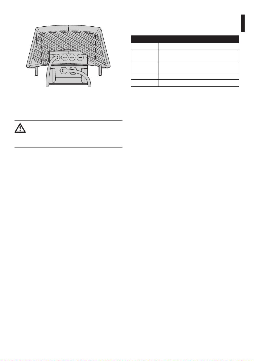
7.1.3 90/240Vac wiring version
Control cable Power supply
Fig. 7
7.1.3.1 90/240Vac version power supply cable
The device is Class I. Connection of the
yellow-green cable to the safety ground
is therefore necessary to ensure electrical
safety.
The illuminator is provided with a 2m power cable.
Blue, brown, yellow/green power cables: Connect
the brown cable to the phase, the blue one to the
neutral and the yellow-green one to the safety
ground.
For maximum distances and recommended cable
sections, refer to the relative paragraph.
7.1.3.2 Telemetry control cable
The product is equipped with a control cable to
manage one input contact and one output contact.
COLORS AND FEATURES OF THE CONTROL CABLE
Cable color Function
Red Input for activation by means of a volt free
relay contact
Green Input for activation by means of a volt free
relay contact
White Clean contact output (Follow)
Black Clean contact output (Follow)
Tab. 2
Input contact: It allows a remote activation of the
illuminator by means of a clean contact placed
between the ends of the red and green cables. For a
proper operation, ensure that the photocell has been
disabled (Fig. 9, page9). The input contact status is
the following:
• Open contact input (insulated red and green
poles): Illuminator on
• Short-circuit contact input (red and green poles
in short-circuit): Illuminator o
Output contact (Follow): The Follow output has
a clean contact in the white and black poles. The
Follow contact can be used to turn on or o other
illuminators simultaneously in the system or to verify
the camera day/night status. The Follow contact
status is the following:
• Open contact output (insulated white and black
poles): Illuminator on
• Short-circuit contact output (white and black
poles in short-circuit): Illuminator o
Instructions manual - English - EN
7
7.1.4 Maximum cable length
Depending on the type of illuminator and supply
voltage, comply with the following maximum
distances for the power cables.
Power supply 12Vdc: A 0.6V voltage drop is allowed
on the cables. Minimum voltage of 11.4Vdc at the
power cable input provided with the illuminator.
CABLES SPECIFICATIONS 12VDC POWER SUPPLY
Cable section (mm²)
0.75 18 4.5
1 17 6.5
EN - English - Instructions manual
1.5 16 9
2.5 14 15
4 10 24
Tab. 3
Power supply 24Vac: Maximum 3V voltage drop is
allowed on the cable. Minimum voltage of 21Vac at
the power cable input provided with the illuminator.
CABLES SPECIFICATIONS 24VAC/VDC POWER
SUPPLY
Cable section (mm²)
0.75 18 35
1 17 50
1.5 16 80
2.5 14 120
4 10 200
Tab. 4
AWG Maximum distance (m)
AWG Maximum distance (m)
Power supply 90/240Vac: The cable section is less
critical, therefore, it is sucient to ensure that the
ground connections is ecient for safety reasons.
We recommend using a section of at least 0.75mm²
(AWG18).
Control cable: External command, Colours red and
Green. Follow command, colours White and Black.
Use a minimum section cable of 0,34mm² (AWG22)
and a minimum distance of 200m.
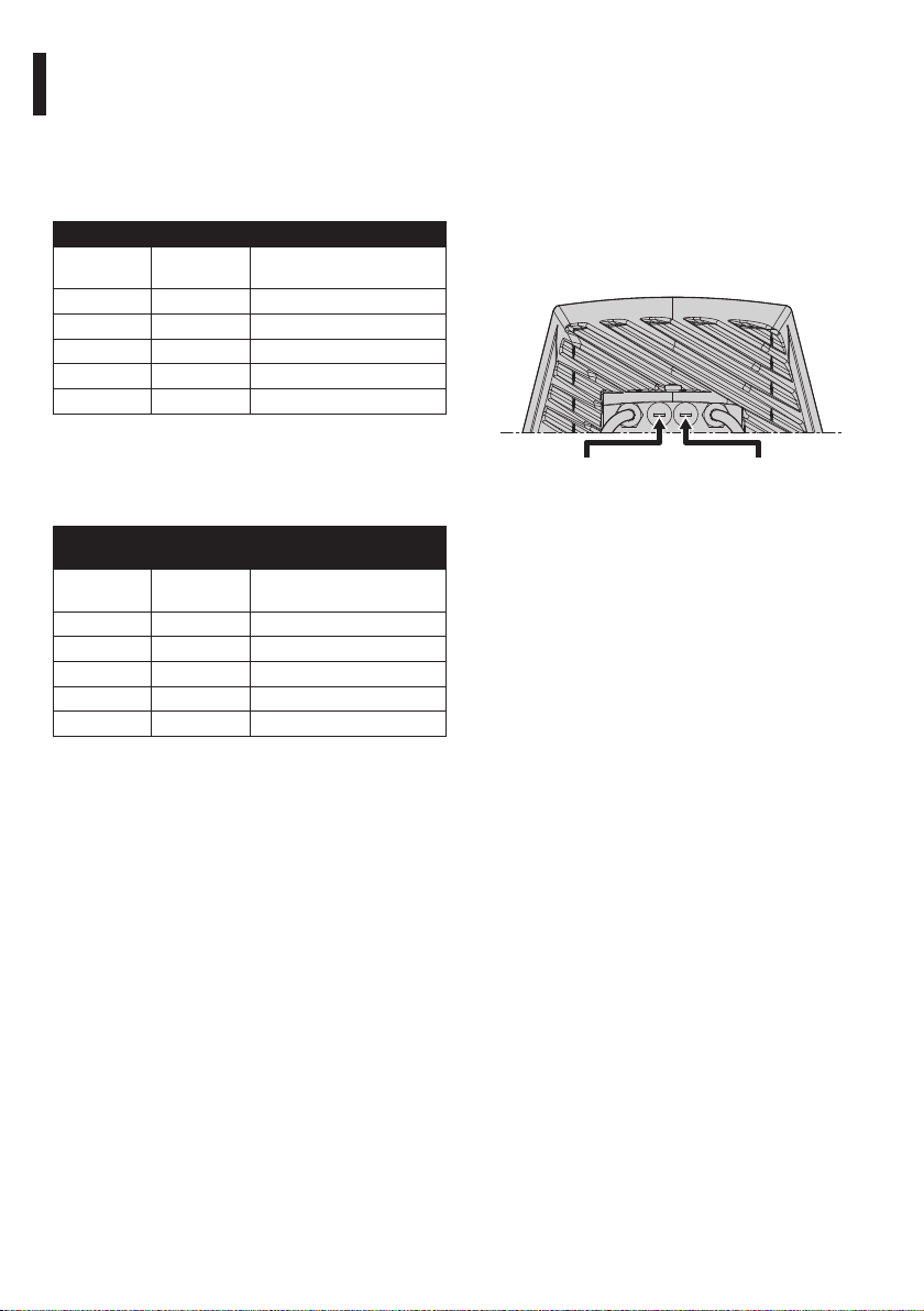
7.1.5 Adjusting the activation threshold
Switch-on threshold
regulation
Fig. 8
7.1.5.1 Photocell sensitivity
The illuminator has an integrated photocell that
allows its automatic activation and deactivation at
predened luminous conditions.
The photocell is set in the factory at a predetermined
luminous level, suitable for most installations
(approximately 50Lux). In the event the intervention
threshold (illuminator activation) must be adjusted
dierently, loosen the plug on the illuminator rear
and proceed adjusting.
Infrared illuminators
power setting
8
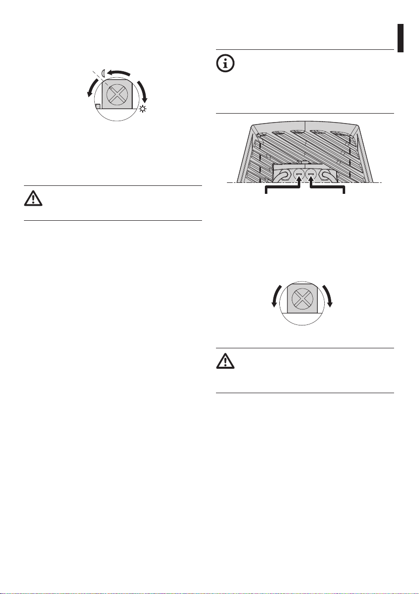
Using a Phillips screwdriver, turn the trimmer
anticlockwise to make the illuminator switch on in
low brightness conditions or clockwise to make it
switch on in better brightness conditions.
OFF
Fig. 9
Adjust the trimmer slowly, in the preset brightness
conditions, until the warning light next to the
trimmer turns on. Once you pass the threshold (LED
on), turn slightly back in the opposite direction.
After making the adjustments make sure
that the plug is closed tight to ensure
perfect sealing.
7.1.5.2 Disabling the photocell
To disable the illuminator (photocell) activation,
fully rotate the photocell adjusting trimmer
counterclockwise (Fig. 9, page9). This way the
illuminator is activated. To deactivate the illuminator,
act on the external command.
7.1.6 Adjusting the power of the
infrared illuminators
The illuminator is set in the factory to
provide maximum power. If long distances
should not be reached or if the image is
over-exposed for excessive brightness,
decrease the power, so that energy saving is
also obtained.
Switch-on threshold
regulation
Fig. 10
To adjust the power of the infrared illuminator, loosen
the hermetic plug. Then adjust the potentiometer,
clockwise to enhance the power of the infrared
illuminators and anti-clockwise to decrease it.
Infrared illuminators
power setting
MAX POWERMIN POWER
Instructions manual - English - EN
Fig. 11
After the adjustments, ensure that the
blanking plugs are appropriately tightened
to ensure that the product is hermetically
sealed.
9
7.2 Operational test
7.2.1 Checking the power supply
Depending on the type of illuminator, ensure that the
supply voltage is within the range.
POWER SUPPLY
Illuminator power supply Range
120-230Vac 10%
24Vac/Vdc 10%
12Vdc 5%
Tab. 5
EN - English - Instructions manual
7.2.2 Checking the photocell’s operation
Verify the photocell functions plugging it with black
tape.
8 Disposal of waste materials
This symbol mark and recycle system
are applied only to EU countries and not
applied to the countries in the other area of
the world.
Your product is designed and manufactured with
high quality materials and components which can be
recycled and reused.
This symbol means that electrical and electronic
equipment, at their end-of-life, should be disposed of
separately from your household waste.
Please dispose of this equipment at your local
Community waste collection or Recycling centre.
In the European Union there are separate collection
systems for used electrical and electronic products.
9 Technical data
9.1 General
Die cast aluminium body
Supplied complete with horizontal and vertical
rotating support in painted galvanized steel and
painted aluminium
Wavelengths 850, 940 nm
9.2 Mechanical
Dimensions: see drawings
9.3 Electrical
Power supply: 24Vac, 12-24Vdc and 90/240Vac
Consumption: 30W
State of the art SMD LED
Adjustable built-in photocell for automatic activation
and deactivation
Input for activation by means of a volt free relay
contact
Clean contact output (Follow)
Multipolar cable L: 2m (6.56ft)
- Telemetry: 4x0.34mm² (AWG22)
- Power supply 24Vac,12/24Vdc: 2x0.75mm²
(AWG18)
- Power supply 90/240Vac: 3x0.75mm² (AWG18)
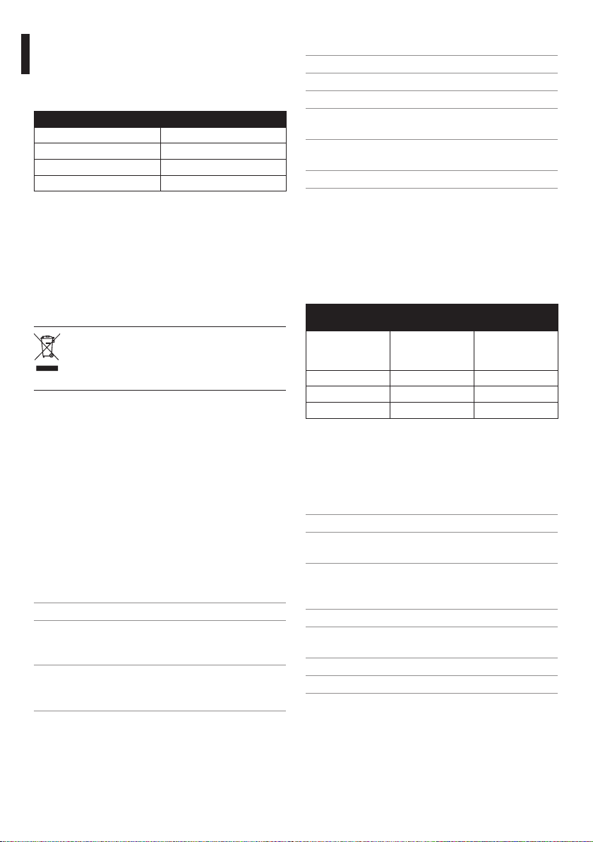
9.4 Illuminators
GEKO IRN BEAM PATTERN AND ACHIEVABLE DISTAN
CES FOR ONE ILLUMINATOR
Horizontal/
vertical beam
patterns
10˚ 240m 140m (460ft)
30˚ 130m 80m (262ft)
60˚ 80m (262ft) 60m (197ft)
Tab. 6 Achievable distance with: BOSCH LTC0620/11 Day/
Night camera. COMPUTAR lens H30Z1015 10-300mm,
F1.5. The typical distance of the subject to illuminate is
in function of the reection coecient of the illuminated scene.
850nm 940nm
9.5 Environment
Indoor / Outdoor
Operating temperature: -50°C/+60°C (with illuminator
on)
IP66/IP67 according to EN60529
9.6 Certications
Electrical safety: EN60598
Photobiological safety of lamps and lamp systems:
EN 62471
Electromagnetic compatibility: EN55022, Class A
Immunity: EN50130-4
FCC Part 15, Class A
10
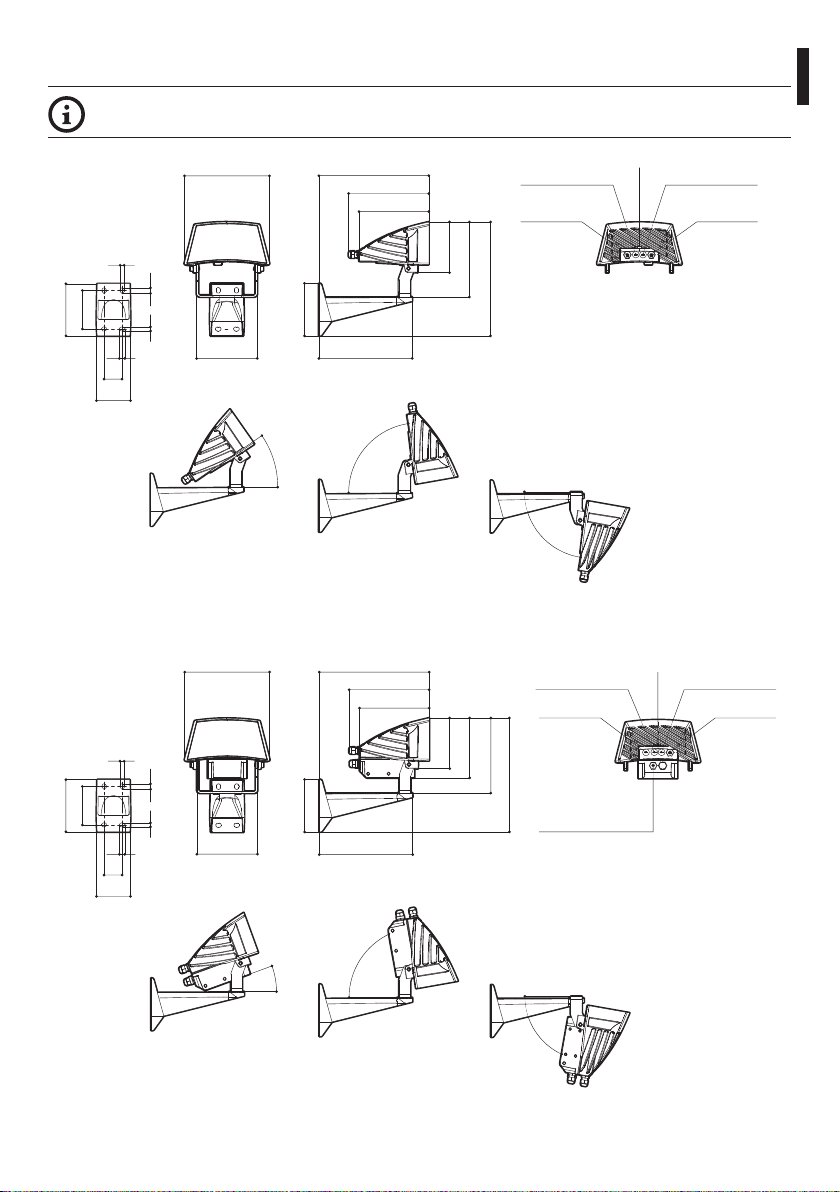
10 Technical drawings
The dimensions are in millimetres.
187
9
12
85
116
Fig. 12 GEKO IRN. 24Vac/12-24Vdc version.
9
12
40
75
134
35°
187
Instructions manual - English - EN
242
176
153
111
116
206
80°
242
176
153
POWER LIMIT
REGULATION
SIGNAL
CABLE
165
251
80°
POWER LIMIT
REGULATION
SIGNAL CABLE
PHOTOCELL
PHOTOCELL
LIGHT OUTPUT
REGULATION
POWER SUPPLY
CABLE
LIGHT OUTPUT
REGULATION
CAP
9
12
85
116
Fig. 13 GEKO IRN. 90-240Vac version.
9
12
40
75
134
111
132
165
251
116
206
20°
80°
POWER SUPPLY CABLE
80°
11

Headquarters Italy Videotec S.p.A.
Via Friuli, 6 - I-36015 - Schio (VI) Italy
Tel. +39 0445 697411 - Fax +39 0445 697414
Email: info@videotec.com
UK Representative oce
Tel./Fax +44 01353 775438 (Sales)
Tel. +44 0113 815 0047 (Technical support)
Tel. +44 0113 815 0031 (Orders/Shipping dept.)
Email: uksales@videotec.com
France Videotec France S.à.r.l.
Voie du Futur, Zac des Portes - 27100 - Val-de-Reuil, France
Tel. +33 2 32094900 - Fax +33 2 32094901
Email: info@videotec-france.com
Americas Videotec Security, Inc.
35 Gateway Drive, Suite 100 - Plattsburgh, NY 12901 - U.S.A.
Tel. +1 518 8250020 - Fax +1 425 648 4289
Email: usasales@videotec.com - www.videotec.us
Asia Pacic Videotec (HK) Ltd
Unit C 24 Floor - Gold King Industrial Building
35-41, Tai Lin Pai Road - Kwai Chung, NT, Hong Kong
Tel. +852 2333 0601 - Fax +852 2311 0026
Email: info@videotec.com.hk
www.videotec.com
MNVCIRN_1214_EN
GEKO IRN
Illuminatore a LED
IT
Italiano - Manuale di istruzioni

Sommario
ITALIANO
1 Informazioni sul presente manuale ............................................................................. 3
1.1 Convenzioni tipograche ..................................................................................................................................... 3
2 Note sul copyright e informazioni sui marchi commerciali ........................................ 3
3 Norme di sicurezza ........................................................................................................ 3
4 Identicazione ............................................................................................................... 4
4.1 Descrizione e designazione del prodotto ....................................................................................................... 4
4.2 Marcatura del prodotto ......................................................................................................................................... 4
5 Dichiarazione di conformità alle norme di prodotto .................................................. 4
6 Preparazione del prodotto per l'utilizzo ...................................................................... 4
6.1 Disimballaggio e contenuto ................................................................................................................................ 4
6.1.1 Disimballaggio .......................................................................................................................................................................... 4
6.1.2 Contenuto .................................................................................................................................................................................. 4
6.2 Lavoro preparatorio prima dell’installazione ................................................................................................. 4
6.3 Smaltimento in sicurezza dei materiali di imballaggio .............................................................................. 5
7 Assemblaggio e installazione ....................................................................................... 5
7.1 Installazione ............................................................................................................................................................... 5
7.1.1 Installazione dell'illuminatore a muro.............................................................................................................................. 5
7.1.2 Cablaggio versione 24Vac e 12/24Vdc ............................................................................................................................. 6
7.1.2.1 Cavo di alimentazione versione 24Vac e 12/24Vdc .......................................................................................................................... 6
7.1.2.2 Cavo di controllo telemetria ..................................................................................................................................................................... 6
7.1.3 Cablaggio versione 90/240Vac ........................................................................................................................................... 7
7.1.3.1 Cavo di alimentazione versione 90/240Vac ........................................................................................................................................7
7.1.3.2 Cavo di controllo telemetria ..................................................................................................................................................................... 7
7.1.4 Lunghezza massima cavi ...................................................................................................................................................... 8
7.1.5 Regolazione soglia di accensione ...................................................................................................................................... 8
7.1.5.1 Sensibilità fotocellula .................................................................................................................................................................................. 8
7.1.5.2 Disabilitazione della fotocellula .............................................................................................................................................................. 9
7.1.6 Regolazione della potenza degli infrarossi .................................................................................................................... 9
7.2 Verica di funzionamento ...................................................................................................................................10
7.2.1 Controllo dell’alimentazione elettrica ............................................................................................................................10
7.2.2 Controllo delle funzioni della fotocellula ......................................................................................................................10
8 Smaltimento dei riuti ................................................................................................ 10
9 Dati tecnici ...................................................................................................................10
9.1 Generale .................................................................................................................................................................... 10
9.2 Meccanica ................................................................................................................................................................. 10
9.3 Elettrico .....................................................................................................................................................................10
9.4 Illuminatori ............................................................................................................................................................... 10
9.5 Ambiente ..................................................................................................................................................................10
9.6 Certicazioni ............................................................................................................................................................ 10
10 Disegni tecnici ........................................................................................................... 11
 Loading...