

VideoSystemer Digital Video Recorder Operating Instruction
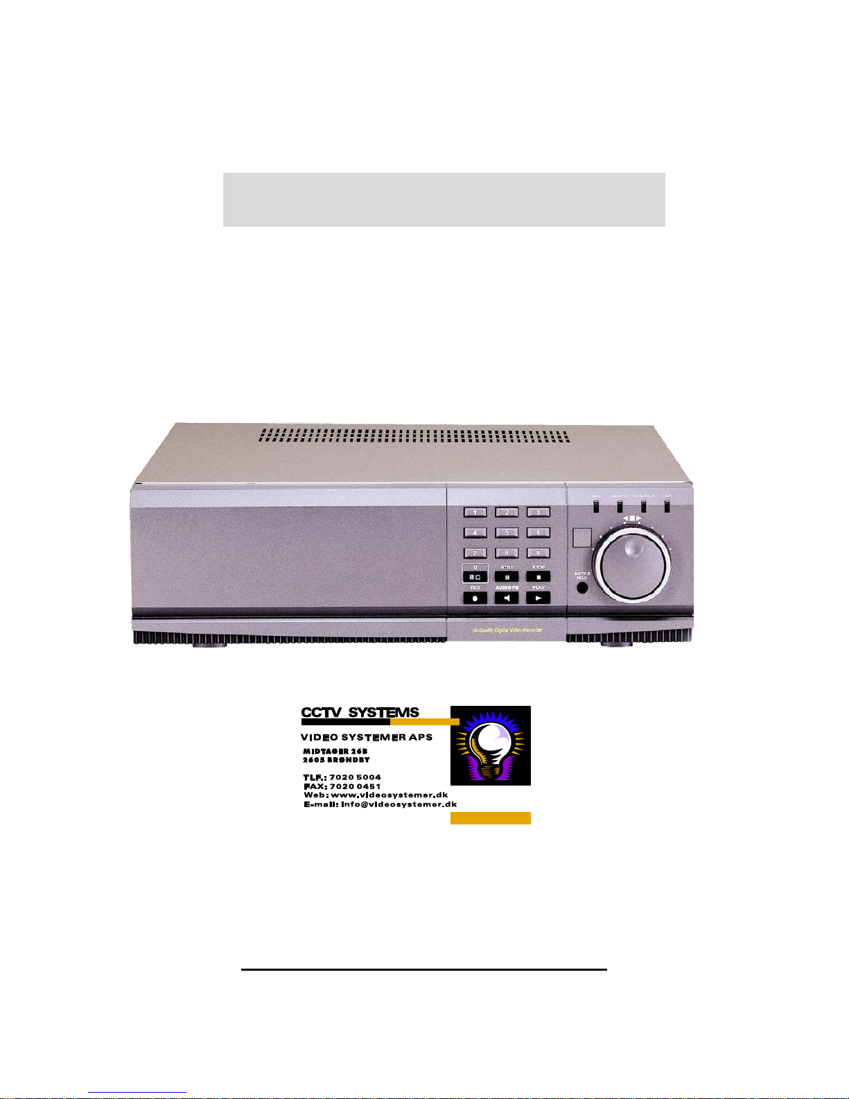
Operating Instruction
Digital Video Recorder
____________________________________________________________________________________________
DIGITAL VIDEO RECORDER
2
SAFETY PRECAUTIONS
CAUTION
RISK OF ELECTRIC SHOCK
DO NOT OPEN
CAUTION:
TO REDUCE THE RISK OF ELECTRIC SHOCK, DO NOT REMOVE
COVER (OR BACK). NO USER SERVICEABLE PARTS INSIDE.
REFER SERVICING TO QUALIFIED SERVICE PERSONNEL.
The lightning flash with arrowhead symbol, within an
equilateral triangle, is intended to alert the user to the
presence of uninsulated “dangerous voltage” within
the product’s enclosure that may be of sufficient
magnitude to constitute a risk of electric shock to
persons.
The exclamation point within an equilateral triangle is
intended to alert the user to the presence of important
operating and maintenance (servicing) instructions in
the literature accompanying the appliance.
WARNING:
TO PREVENT FIRE OR ELECTRIC SHOCK HAZARD, DO NOT EXPOSE

____________________________________________________________________________________________
DIGITAL VIDEO RECORDER
3
THIS APPLIANCE TO RAIN OR MOISTURE.
PRECAUTIONS
• Refer all work related to the installation of this product to qualified service personnel or
system installers.
• Do not block the ventilation opening or slots on the cover.
To prevent the appliance from overheating, place it at least 5 cm (2 inches) away from
the wall.
• Do not drop metallic parts through slots.
This could permanently damage the appliance. Turn the power off immediately and
contact qualified service personnel for service.
• Do not attempt to disassemble the appliance.
To prevent electric shock, do not remove screws or covers. There are no user-
serviceable parts inside. Contact qualified service personnel for maintenance.
• Handle the appliance with care.
Do not strike or shake, as this may damage the appliance.
• Fully charge up the backup battery.
Keep the appliance turned on for at least 48 hours to recharge the backup battery. This
procedure is necessary when using the appliance for the firs time or after it has been
unplugged for a long time from the AC outlet. Insufficient charging of the battery may
cause erasure of settings if the AC power supply should fail. The battery, if fully
charged, will back up the settings for 480 hours in an ordinary environment.
• Do not expose the appliance to water or moisture, nor try to operate it in wet areas.
Do take immediate action if the appliance becomes wet. Turn the power off and refer
servicing to qualified service personnel. Moisture may damage the appliance and also
cause electric shock.
• Do not use strong or abrasive detergents when cleaning the appliance body.
Use a dry cloth to clean the appliance when it is dirty. When the dirt is hard to remove,
use a mild detergent
and wipe gently.
• Do not operate the appliance beyond its specified temperature, humidity or power source ratings.
Do not use the appliance in an extreme environment where high temperature or high humidity
exists.
Use the appliance at temperatures within +5°C - +40°C (41°F - 104°F) and a humidity below
90 %.

____________________________________________________________________________________________
DIGITAL VIDEO RECORDER
4
The input power source for this appliance is 110V-220V AC 50/60Hz.
Contents
Ⅰ Controls
1. Front Panel
2. Rear Panel
3. Remote Controller
Ⅱ Installation & Connections
1. Camera, Monitor, Microphone, Alarm sensor and Power cord
2. Alarm inputs and Alarm outs
3. External Backup Device.
4. PAN/TILT/ZOOM Camera
5. NETWORK
Ⅲ Programming
1. Main Menu
2. Display Set
3. Record Set
4. Group Recording Set & Motion Detection Set
5. Alarm Recording Set
6. Schedule Recording Set
7. Time & Date Set
8. System Set
9. Network Set

____________________________________________________________________________________________
DIGITAL VIDEO RECORDER
5
Ⅳ Operation
1. Basic Recording
2. Alarm Recording
3. Schedule Recording
4. Motion Detection Recording
5. Playback
6. Time & Date Search
7. Alarm List Search
8. Information & Log List
9. Zoom
10. PAN/TILT/ZOON Camera Control
11. External Backup Device Control (DAT24)
Ⅴ Client Program
1. How to install and connect?
2. Features
3. Image file down load from the DVR server
4. DVR Setting
5. Local Player
Ⅵ How to connect modem
Ⅶ Specification & Contents
1. Specification
2. Contents
____________________________________________________________________________________________
DIGITAL VIDEO RECORDER
6
Ⅰ Controls
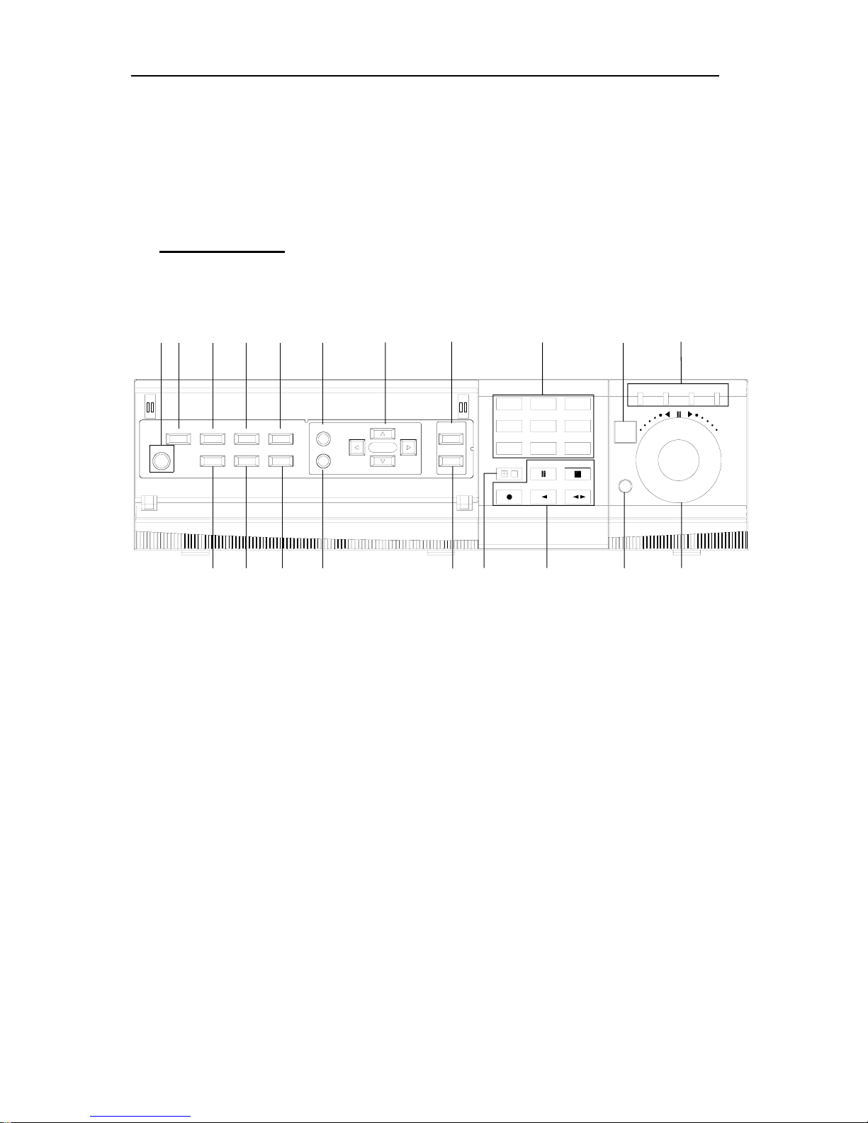
1. Front Panel Controls
POWER
LOCK
ZOOM
INFO
BACKUP
RESTORE
P/T/Z/FOCUS
SCHEDULE
CLEAR
MENU
CURSOR
Digital Surveillance Recorder
REC AUDIO-PB
0 STILL
PLAY
STOP
HOLD
SHUTTLE
ALARM
SEARCH
SEARCH
TIME
78
4596
123
LOCK
RECPOWER SCHEDULE
12345
67 8910
11 12
131415 16
17 18
19 20
1) POWER button
Press this button to turn the power on; press again to turn the power off. The
POWER LED (red) lights/goes off when the power is on/off. It flashes when
switching during initializing and disk checking.
2) LOCK button
Press this button to lock all unit’s key buttons including the remote controller.
The LOCK LED (green) lights/goes off when the lock is on/off. To release press it
again and enter the password.
3) RESTORE button
Press this button to restore recorded data to the main hard disk from an archive
device only when an external SCSI DAT24 is connected.
4) SCHEDULE button
Press this button to make scheduled recording standby. The SCHEDULE LED
(green) lights/goes off when the schedule is on/off.
5) INFO button
Press the button to display current system information; press again to display log list.

____________________________________________________________________________________________
DIGITAL VIDEO RECORDER
7
6) BACKUP button
Press this button to begin making a backup copy of the hard drive. If there is no
peripheral recording device connected, this button cannot be used.
7) PAN/TILT/ZOOM button
Press this button to control a PAN/TILT/ZOOM camera via RS-232 connection.
8) ZOOM button
Press this button to display zoom area box; press again to enlarge the image. Pressing
cursors can move this zoom area.
9) MENU button
Press this button to display the MAIN MENU screen.
It is also used as EXIT button to exit all kinds of OSD screen.
10) CLEAR button.
In Zoom mode, pressing this button reduces the image.
In stop mode and playback mode, pressing this button disappears time & date OSD.
Pressing it again appears the OSD.
On ‘RECORD GROUP SET’ menu, it sets each channel ‘Motion Detection’.
11) Direction (bcef) buttons.
In Menu setup mode, used to move the cursor.
In Zoom mode, used to move the zoom area.
12) TIME SEARCH button
Press this button to display the Time Search menu.
13) ALARM SEARCH button
Press this button to display the Alarm Search menu.
14) Numeric buttons (NO. 1~9)
Used to enter the password and select the camera numbers.
15) Quad/Sequence, 0 button
Press this button to display the cameras in quad mode or to switch sequence function.
In addition, this button can be used as number 0 to set the password.
16) AUDIO PB button
Press this button to synchronize the sound track with the scenes.
17) Remote control signal receiver.
18) Mode Indicator.
19) SHUTTLE HOLD button
This button retains the selected playback or reverse playback speed.
Rotate the SHUTTLE ring to the desired search speed, and then press the SHUTTLE
HOLD button while holding the SHUTTLE ring at the selected search speed. Search
speed will be maintained even when the SHUTTLE ring is returned to its original
____________________________________________________________________________________________
DIGITAL VIDEO RECORDER
8
position.
20) Jog and shuttle operation
SHUTTLE ring
Use the ring to set various menus and search functions, to adjust the playback speed,
and to rewind or forward the image.
JOG dial
Use the dial to set various menus and search functions, and to forward or reverse the
image during playback (field-by-field).
2.
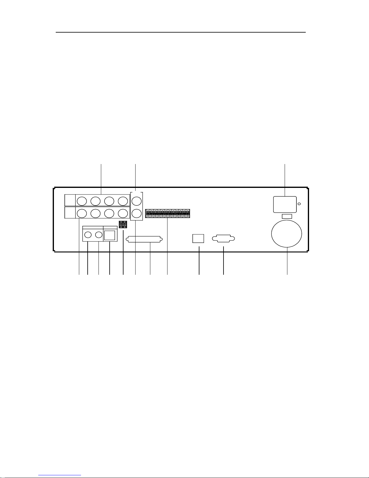
Rear Panel Connectors
R
E
C
S
T
A
R
T
INOUT
SCSI
OUT
IN
CAMERA
CAMERA
AUDIO MIC
1
1
23
23
OFF
ON
75ohm
S-VIDEO
4
4
COMPOSITE
VIDEO
OUT
A
L
A
R
M
I
N
4
A
L
A
R
M
I
N
3
A
L
A
R
M
I
N
2
A
L
A
R
M
I
N
1
G
N
D
P
O
W
E
R
O
N
P
O
W
E
R
O
F
F
A
L
A
R
M
O
U
T
P
U
T
G
N
D
ETHERNET
RS-232C
R
E
C
E
N
D
G
N
D
1 2
3 4567 8 9 10 11 12
13
14
1) CAMERA IN connectors
These are BNC input connectors for 4 cameras
2) VIDEO OUT connectors
A BNC standard composite video output connector
3) CAMERA OUT connectors
These are BNC output (looping) connectors for cameras.
4) S-VHS OUT connector
An S-VHS connector for separate luminance and chrominance (Y/C) signals
5) AUDIO OUT connector
This is an RCA output connector for an audio signal.
6) AUDIO IN connector
This is an RCA input connector for an audio signal.
7) MIC jack
This is an input connector for a microphone.

____________________________________________________________________________________________
DIGITAL VIDEO RECORDER
9
8) 75 Ohm Termination switch.
9) SCSI-2 connector
This connector is for peripheral recording device.
10) ALARM IN/OUT terminal.
11) RJ-45 ETHERNET connector
12) RS-232C
13) AC power socket
14) Power Fan
3. Remote Controller

____________________________________________________________________________________________
DIGITAL VIDEO RECORDER
10
POWER
MENU
PLAYT-SEARCH A-SEARCH
REC
STOP STILL
STEP
QUAD
1
2
3
4
56
7
8
9
0
ZOOM
INFO
SCH
CLEAR
BACKUPAUDIO-PB
P/T/Z
SCH
T
RESTORE
LIGHT
A
FAST
POWER
AUDIO-PB
BACKUP
RESTORE
INFORMATION
ZOOM
PAN/TILT/ZOOM
MENU
CLEAR
TIME SEARCH
PALYBACK
ALARM SEARCH
REC STILL
STOP
FAST VIEW FIELD BY FIELD
QUAD SCHEDULE REC ON/OFF
NUMBER
LIGHT
Ⅱ Installation & Connections.
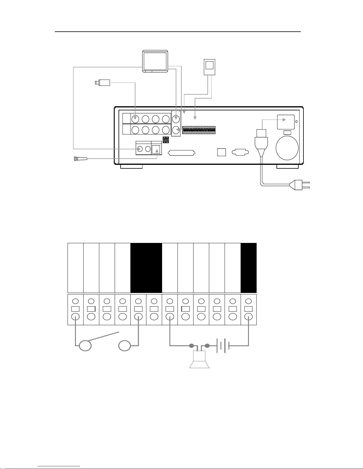
1. Camera, Monitor, Microphone, Alarm sensor and Power cord.
____________________________________________________________________________________________
DIGITAL VIDEO RECORDER
11
R
E
C
S
T
A
R
T
INOUT
SCSI
OUT
IN
CAMERA
CAMERA
AUDIO MIC
1123
23
OFF
ON
75ohm
S-VIDEO
4
4
COMPOSITE
VIDEO
OUT
A
L
A
R
M
I
N
4
A
L
A
R
M
I
N
3
A
L
A
R
M
I
N
2
A
L
A
R
M
I
N
1
G
N
D
P
O
W
E
R
O
N
P
O
W
E
R
O
F
F
A
L
A
R
M
O
U
T
P
U
T
G
N
D
ETHERNET
RS-232C
R
E
C
E
N
D
G
N
D
VIDEO OUT
or
S-VIDEO OUT
AUDIO OUT
Up to 4 cameras
MIC IN
MONITOR
CAMERA#1
MICROPHONE
POWER CORD
SENSOR#1
ALARM IN
GND
2. Alarm inputs and Alarm outs.
ALARM IN 1
ALARM IN 2
ALARM IN 3
ALARM IN 4
GND
GND
GND
ALARM OUTPUT
POWER OFF
POWER ON
REC START
REC END
Connection of N.O (Normally Open)
3. External Backup Device connection.
1) DDS3 HP Sure Store DAT24
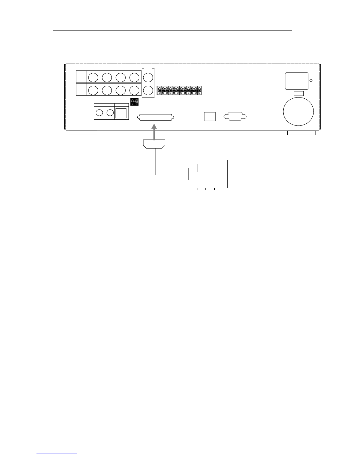
____________________________________________________________________________________________
DIGITAL VIDEO RECORDER
12
2) On-Stream ADR50 (50GB)
3) HDD SCSI-IF Type
R
E
C
S
T
A
R
T
OUT IN
SCSI
OUT
IN
CAMERA
CAMERA
AUDIO MIC
1
1
23
23
OFF
ON
75ohm
S-VIDEO
4
4
COMPOSITE
VIDEO
OUT
A
L
A
R
M
I
N
4
A
L
A
R
M
I
N
3
A
L
A
R
M
I
N
2
A
L
A
R
M
I
N
1
G
N
D
P
O
W
E
R
O
N
P
O
W
E
R
O
F
F
A
L
A
R
M
O
U
T
P
U
T
G
N
D
ETHERNET
RS-232C
R
E
C
E
N
D
G
N
D
SCSI cable
External Back-up Stroage
4. PAN/TILT/ZOOM Camera
1
) C&B Technology (Model: PTZ102)
2) The other models: as buyers request; the camera sample and protocol should be
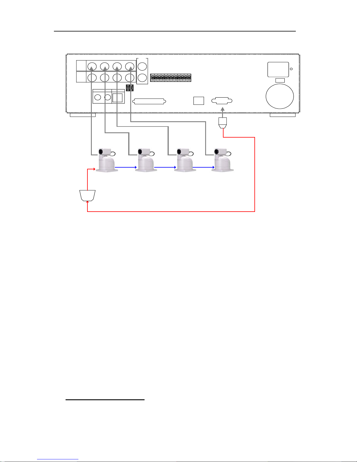
____________________________________________________________________________________________
DIGITAL VIDEO RECORDER
13
supported.
R
E
C
S
T
A
R
T
OUT
IN
SCSI
OUT
IN
CAMERA
CAMERA
AUDIO MIC
1123
23
OFF
ON
75ohm
S-VIDEO
4
4
COMPOSITE
VIDEO
OUT
A
L
A
R
M
I
N
4
A
L
A
R
M
I
N
3
A
L
A
R
M
I
N
2
A
L
A
R
M
I
N
1
G
N
D
P
O
W
E
R
O
N
P
O
W
E
R
O
F
F
A
L
A
R
M
O
U
T
P
U
T
G
N
D
ETHERNET
RS-232C
R
E
C
E
N
D
G
N
D
RS485 to RS232C
PTZ CAMERA
CAM1
CAM2 CAM3 CAM4
CONTROL LINE
5. NETWORK connection.
1) Enter the IP address, Net mask and Gateway on the NETWORK SET
menu
2) PC system requirement.
(a) 200MHz CPU
(b) 64MB RAM
(c) 4MB Video Card
(d) Windows 98, 98SE, 2000, ME
(e) Spare 10-BaseT Ethernet Port
(f) RJ-45 Network Cable
Ⅲ Programming

____________________________________________________________________________________________
DIGITAL VIDEO RECORDER
14
1. MAIN MENU
1) Press the MENU button or SHUTTLE HOLD button to display the MAIN MENU.
2) Press ST buttons or turn the JOG dial to go to the desired sub-menu.
3) Press X button or turn the SHUTTLE ring to the right to enter the desired sub-menu..
4) Press the MENU button to exit the MAIN MENU.
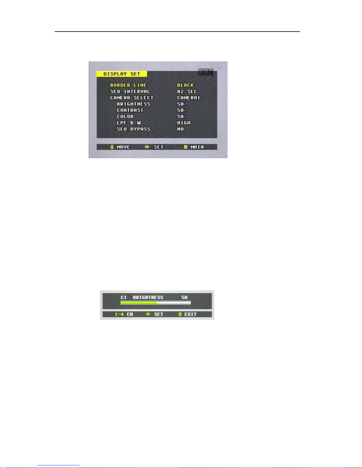
2. DISPLAY SET
1) Press the MENU button or SHUTTLE HOLD button to display the MAIN MENU,
And then, press X button or turn the SHUTTLE ring to the right while the DISPLAY
____________________________________________________________________________________________
DIGITAL VIDEO RECORDER
15
SET flashes. The DISPLAY SET sub-menu appears.
2) Press S T buttons or turn the JOG dial to move to the desired item, and then press
W X buttons or turn the SHUTTLE ring to switch the options.
3) Settings
(a) BORDER LINE colors in quad mode.
BLACK (default) DARK GRAY GRAY WHITE
(b) SEQ INTERVAL: Cameras can be sequenced individually,
and the sequence interval can be adjusted from 1 sec to 5 sec.
01SEC(default) 02SEC 03SEC 04SEC 05SEC
(c) CAMERA SELECT: Select the desired camera, and then the brightness, contrast,
color and sequence bypass of each camera can be adjusted individually.
CAM1 (default) CAM2 CAM3 CAM4
(d) BRIGHTNESS adjustment.
a) Camera number can be switched by pressing the number buttons (1,2,3,4).
b) The brightness of each camera can be adjusted by pressing W X buttons or
by turning the SHUTTLE ring.
(e)
CONTRAST adjustment.

____________________________________________________________________________________________
DIGITAL VIDEO RECORDER
16
5 Camera number can be switched by pressing the number buttons
(1,2,3,4).
6 The contrast of each camera can be adjusted by pressing W X buttons or
by turning the SHUTTLE ring.
(f) COLOR adjustment
a) Camera number can be switched by pressing the number buttons (1,2,3,4).
b) The contrast of each camera can be adjusted by pressing W X buttons or by
turning the SHUTTLE ring.
(g) LPF B/W (Low Pass Filter Bandwidth)
High: recommended for complicated image recording (Outside)
Low: recommended for simple image recording (Inside)
(g) SEQ. BYPASS (YES, NO)
If the SEQ. BYPASS is YES, then the selected camera will not be shown in the
sequential display mode.
To complete the setting and return to the MAIN MENU, press MENU button or
SHUTTLE HOLD button.
*NOTE:
Screen vertical position adjustment.
- The vertical position of monitoring screen can be adjusted upward/downward by pressing the
S or T button on the front panel/ remote controller in the Stop/Recording mode.
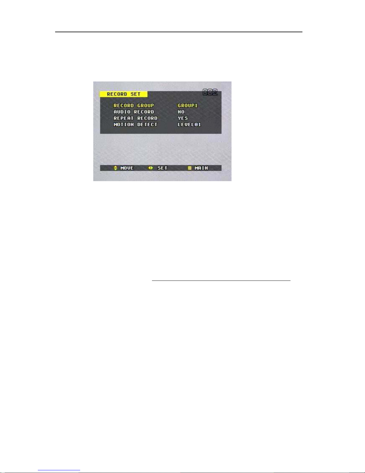
3. RECORD SET
____________________________________________________________________________________________
DIGITAL VIDEO RECORDER
17
1) Press the MENU button or SHUTTLE HOLD button to display the MAIN MENU,
And then, go to the RECORD SET using ST buttons or the JOG dial.
2) Press the X button or turn the SHUTTLE ring to the right while the RECORD SET
flashes. The RECORD SET sub-menu appears.
3) Press S T buttons or turn the JOG dial to move to the desired item, and then press W
X buttons or turn the SHUTTLE ring to switch the options.
4) Settings
(a) RECORD GROUP
Select the current recording group you wish to record.
* Refer to the REC GROUP SET.
GROUP1 (default) GROUP2 GROUP3 GROUP4
(b) AUDIO RECORD
NO (default) MIC LINE
(c) REPEAT RECORD (applies to both internal main HDD and external SCSI DISK)
YES (default): the recorder overwrites data repeatedly from the beginning of
HDD when the end of the disk is reached during recording.
NO: the recorder stops recording when the end of the disk is reached.
(d) MOTION DETECT: Sensitivity of Motion Detection (Duration: 1 Min)
Sensitivity Level; LEVEL 1(Low sensitivity) – LEVEL 15(High sensitivity)
To complete the setting and return to the MAIN MENU, press MENU button or
SHUTTLE HOLD button..
4. RECORD GROUP SET & MOTION DETECTION SET

____________________________________________________________________________________________
DIGITAL VIDEO RECORDER
18
1) Press the MENU button or SHUTTLE HOLD button to display the MAIN MENU,
And then, go to the REC GROUP SET using ST buttons or the JOG dial.
2) Press the X button or turn the SHUTTLE ring to the right while the REC GROUP
SET flashes. The REC GROUP SET sub-menu appears.
3) Press S T buttons or turn the JOG dial to move to the desired item, and then press W
X buttons or turn the SHUTTLE ring to switch the options.
4) Settings
(a) DEFINE GROUP
Select the group number you wish to define the picture quality and capture rates.
GROUP1 (default) GROUP2 GROUP3 GROUP4
(b) PICTURE QUALITY
Set the quality of the video picture for all cameras
SUPER+ (default) SUPER HIGH+ HIGH
MID+ MID LOW+ LOW
CAMERA1 ~ CAMERA4
Set the capture rate of each camera.
NTSC setting
CAMERA 1 & CAMERA 2: Real-Time recording
30F/S
15F/S (default)12F/S10F/S6F/S5F/S4F/S
3F/S 2F/S1F/S0F/S
CAMERA 3 & CAMERA 4: Max. 15F/S
15F/S(default)12F/S10F/S06F/S05F/S04F/S03F/S
02F/S01F/S00F/S
PAL setting
CAMERA 1 & CAMERA 2: Real-Time recording
25F/S
12F/S (default) 10F/S8F/S6F/S5F/S
4F/S 2F/S1F/S0F/S
 Loading...