

VideoSys IDU User Manual
WWW.VIDEOSYS.TV 1
IDU User Manual
Revision 3.0.1 01/05/2018
Videosys Broadcast Ltd
Unit 1-2 Forest Farm Barn
Turners Hill Road
Turners Hill
West Sussex, RH10 4QH
Tel: +44 1293 541200
www.videosys.tv

WWW.VIDEOSYS.TV 2
Contents
Your Camera Control Indoor Unit ............................................................................ 3
Front Panel ........................................................................................................ 3
Rear Panel......................................................................................................... 3
Getting Started ..................................................................................................... 4
Introduction ...................................................................................................... 4
Principal of Operation ......................................................................................... 4
Uni-directional ................................................................................................ 4
Bi-directional .................................................................................................. 5
Connecting Components ..................................................................................... 6
RCP ............................................................................................................... 6
ODU .............................................................................................................. 6
Tally .............................................................................................................. 6
Power ............................................................................................................ 6
Navigating Menus .................................................................................................. 7
Status Screens .................................................................................................. 7
Uni-directional Status Screen ............................................................................ 7
Bi-directional Status Screen ............................................................................. 7
Menu Structure .................................................................................................. 8
Web Interface .................................................................................................... 9
Accessing the Web Interface ............................................................................. 9
Navigating the Web Interface ......................................................................... 10
Unit Updates ................................................................................................... 11
Specification ....................................................................................................... 12
Supported Cameras & Commands ...................................................................... 12
Physical Parameters ......................................................................................... 12
Electrical Parameters ........................................................................................ 12
Backwards Compatibility ...................................................................................... 13
Connector Wiring Diagrams .................................................................................. 13
Data Out ......................................................................................................... 13
Power Input Connector ..................................................................................... 13
RCP legacy connectors ...................................................................................... 14
Generic Connectors ....................................................................................... 14
Sony Connectors ........................................................................................... 14
Bi-directional Data Return Port .......................................................................... 15
Tally Input Connector ....................................................................................... 15
WWW.VIDEOSYS.TV 3
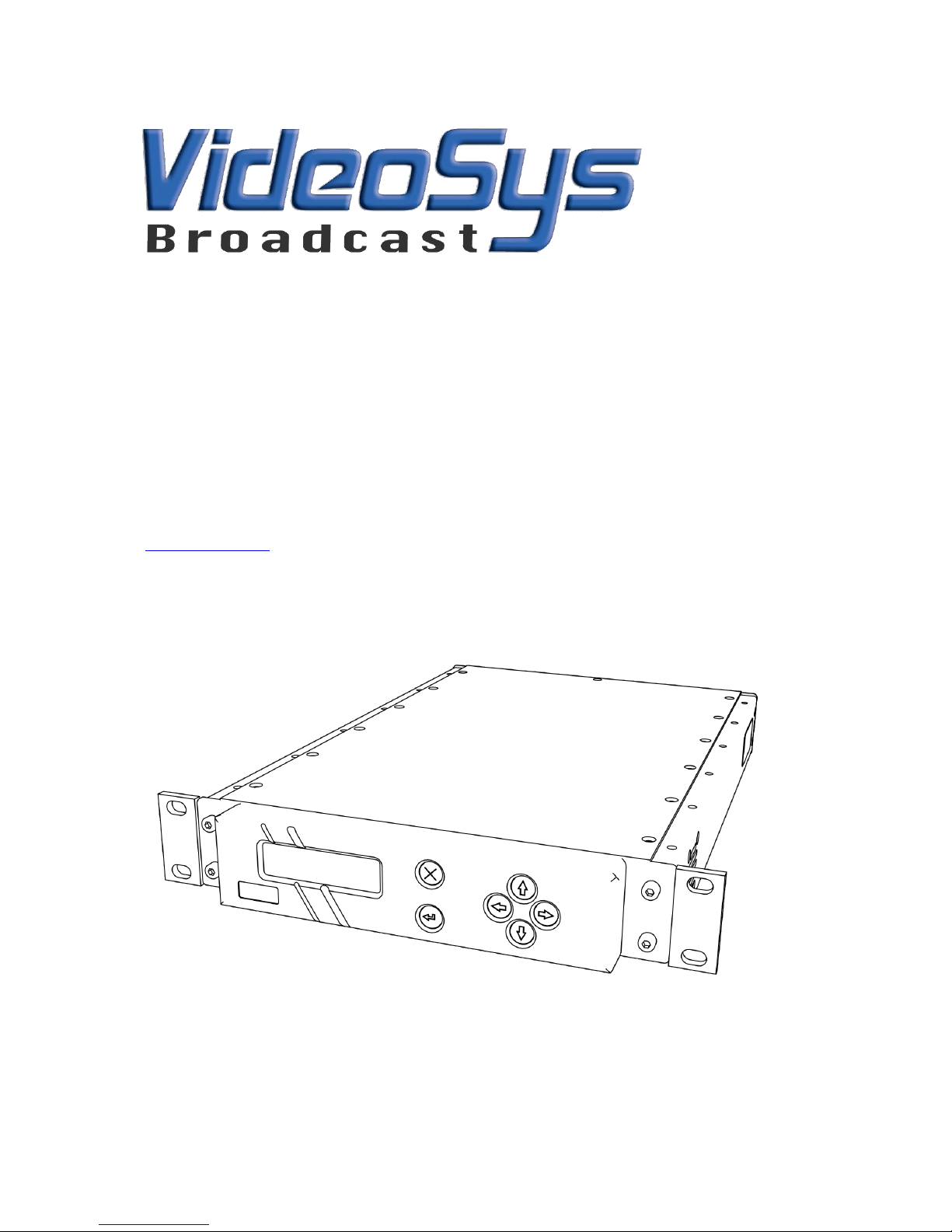
Your Camera Control Indoor Unit
Front Panel
1. OLED Display
2. Cancel Button
3. Up Button
4. Right Button
5. Down Button
6. Left Button
7. Enter Button
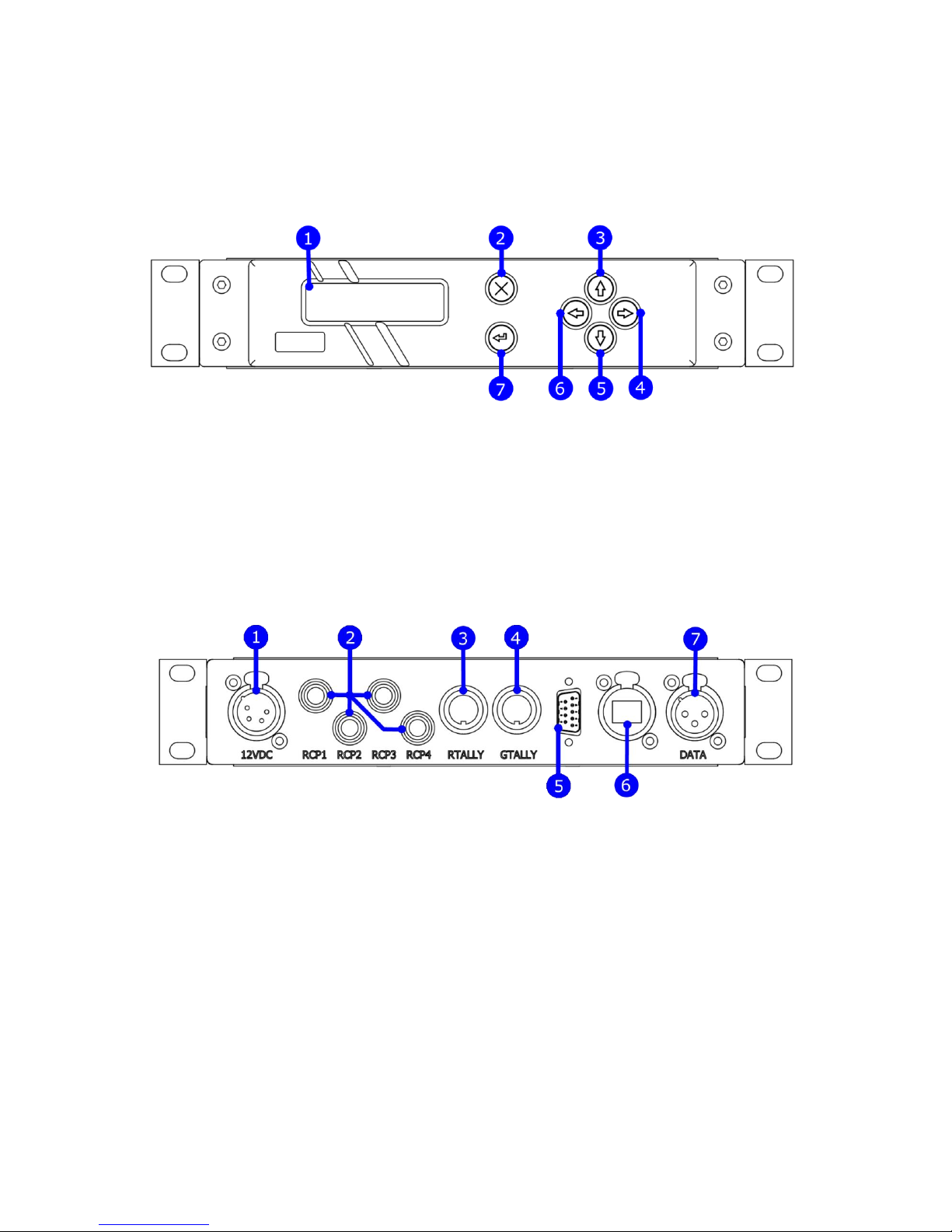
Rear Panel
1. Power Input Connector (4 Pin XLR, Male)
2. Legacy Camera Connectors (Either ‘Generic’ or ‘Sony’ as specified upon ordering)
3. Red Tally Input Connector (8 pin DIN)
4. Green Tally Input Connector (8 pin DIN)
5. Bi-directional Data Return Connector (D9)
6. Ethernet Connector (RJ45)
7. Data Output Connector (3 Pin XLR, Female)

WWW.VIDEOSYS.TV 4
Getting Started
Thank you for purchasing a Videosys IDU, we hope that you will find the necessary
information within this manual and our specific quick setup guides, if however, you
require additional support please don’t hesitate to contact your local distributor.
Introduction
The Videosys camera control system allows you to replace the cables between your
Remote Control Panels, Camera Control Units and Cameras, the Videosys IDU connects
directly to existing control panels and in combination with other components from the
Videosys camera control range will provide a robust broadcast quality solution.
The Videosys camera control solution consists of three distinct components; an ‘IDU’ (In
Door Unit), ‘ODU’ (Out Door Unit) and an ‘RX’ (Receiver). Multiples of these components
can be used to best fit the operators’ requirements, for example multiple IDU’s can be
connected to allow for many camera control paths over one ODU. Multiple ODU’s can be
used to increase RF coverage, and each camera to be controlled requires an RX.
From this point on to avoid ambiguity and keep things concise, the terms IDU, ODU, RCP
and RX will be used.
Principal of Operation
Our camera control system can be configured to operate using one of two fundamentally
different architectures, descriptions of the architectures and their relative advantages
and drawbacks are as follows:
Uni-directional
In this mode the IDU acts as a ‘Virtual Camera’ and talks to the RCP via its native
protocol. Changes to this Virtual Camera are then encoded into our low latency protocol.
Encoded data is routed from the IDU to the ODU where it is transmitted. Data is then
received via the RX, within the RX a ‘Virtual Panel’ is updated with the received
information, the ‘Virtual Panel’ then communicates with the camera using its native
protocol.
• This approach allows high performance even within an extremely poor RF
environment; as data loss will not cause link failure.
• Uni-directional operation boasts simple setup, as only one data path needs to be
configured.
• Due to the use of an intermediate protocol, Uni-directional operation allows
operators to mix and match different manufacturers cameras and control panels.
• As each command has to be specifically implemented and handled, not all of the
features available on manufacturers cameras and control panels will be available
when used with a Uni-directional control link.
WWW.VIDEOSYS.TV 5
Bi-directional
In this mode an RCP natively communicates to the IDU, data is then conditioned and
forwarded on to the ODU, where it is then transmitted. An RX then receives transmitted
data and communicates with the manufacturers camera. Return data is fed from the RX
via a return path, back to the IDU. Typically, this return path would be via the data path
provided on many COFDM video transmitters.
• All of the features that would be available via a cabled setup are available via our
Bi-directional setup.
• Due to the bandwidth restrictions of the RF path, RCP wakeup times might be
slightly longer than in a wired or Uni-directional set up.
• Because of the reliance on two communication paths, wireless control is not as
robust as with Uni-directional operation.
Depending on the specific requirements of your application, Bi-directional or Unidirectional should be selected.
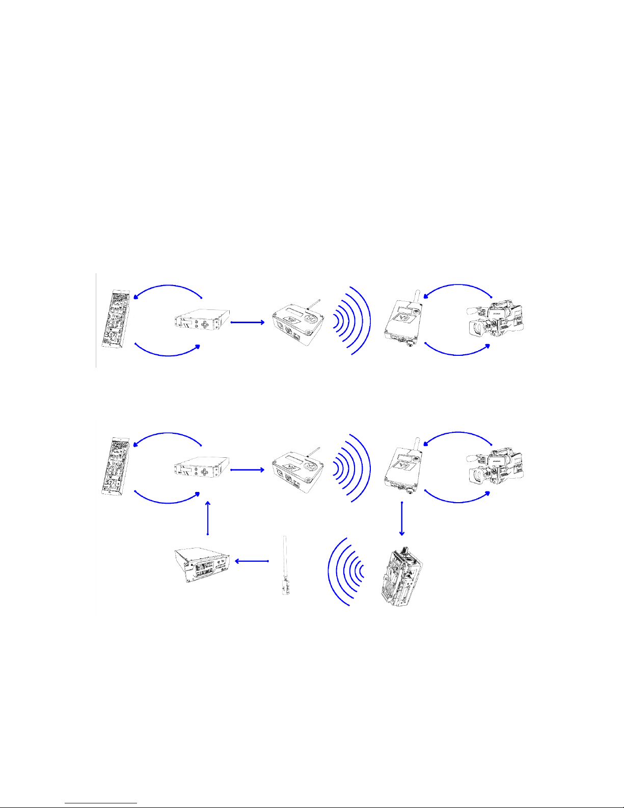
Fig 1. A simple uni-directional camera control setup
Fig 2. A simple bi-directional camera control setup utilising return via
videolink data path
 Loading...