

Videoswitch VS-200 User Manual

VS-Series Desktop Switchers
VS-201 2 Camera Switcher
VS-202 2 Camera Switcher with Alarms & Remote Control
VS-401 4 Camera Switcher
VS-402 4 Camera Switcher with Alarms & Remote Control
VS-601 6 Camera Switcher
VS-602 6 Camera Switcher with Alarms & Remote Control
VS-801 8 Camera Switcher with Dual Monitor Outputs
VS-802 8 Camera Switcher with Dual Monitor Outputs, Alarms & Remote Control
Document Ref: Vs680a.doc
Date: 10/02/2003
User Manual
Products covered by this manual:
Videoswitch Telephone 01252-851510
Units 15 & 16 Fax 01252-851296
Redfields Industrial Park Email sales@videoswitch.co.uk
Redfields Lane Web www.videoswitch.co.uk
Church Crookham
Hants GU52 0RD
England

Videoswitch VS-Series Desktop Switchers
Contents:
1 Installation................................................................................................................................2
1.1 Connecting Up..............................................................................................................................................................................2
1.2 Termination ..................................................................................................................................................................................2
2 Operation...................................................................................................................................3
2.1 Power-Up .....................................................................................................................................................................................3
2.2 Manual Switching ......................................................................................................................................................................... 3
2.3 Auto Sequencing..........................................................................................................................................................................3
2.4 Dual Monitor Switchers ................................................................................................................................................................3
2.5 Restore Factory Defaults..............................................................................................................................................................3
2.6 Reset Camera Titles.....................................................................................................................................................................3
3 Configuration Menu................................................................................................................4
3.1 ◄ Back.........................................................................................................................................................................................4
3.2 Auto Sequence List (Monitor A or B)............................................................................................................................................4
3.3 Auto Sequence Time (Monitor A or B) .........................................................................................................................................4
3.4 Auto Sequence Mode (Monitor A or B) ........................................................................................................................................4
3.5 Alarm Hold Time...........................................................................................................................................................................4
3.6 Alarm Sequence Time..................................................................................................................................................................4
3.7 Restore Camera after Alarm ........................................................................................................................................................4
3.8 Relay Hold Time...........................................................................................................................................................................4
3.9 Alarms Normally Open or Closed.................................................................................................................................................4
3.10 Text Mode ....................................................................................................................................................................................4
3.11 Camera Titles...............................................................................................................................................................................4
3.12 Screen Title .................................................................................................................................................................................. 4
3.13 Power Up States ..........................................................................................................................................................................4
3.14 Remote Control Address ..............................................................................................................................................................4
4 Alarms & Remote Control.....................................................................................................5
4.1 Alarms .......................................................................................................................................................................................... 5
4.2 RS485 Remote Control ................................................................................................................................................................5
4.3 RS232 Remote Control ................................................................................................................................................................5
1
Videoswitch VS-Series Desktop Switchers
A
1 Installation
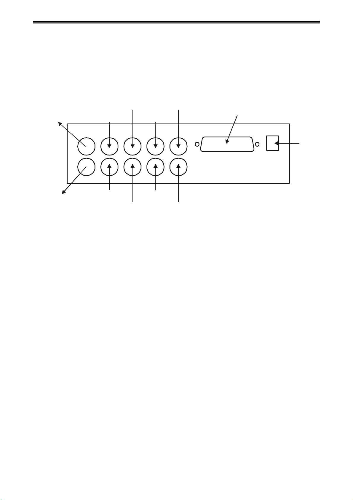
1.1 Connecting Up
Connect cameras and monitor(s) to the BNC connectors as shown below. This diagram shows a VS-800
Series switcher. Note that on other models some of the connectors are absent.
CAMERA 8
CAMERA 7
LARM INPUTS & OUTPUTS
MONITOR “A”
MONITOR “B”
CAMERA 4
CAMERA 2
CAMERA 1
CAMERA 3
CAMERA 6
CAMERA 5
1.2 Termination
If any camera inputs need to be un-terminated, remove the switcher’s base and carefully cut out the 75W
resistors R1 to R8 as required (Resistors R1, R2... relate to Camera1, Camera2...). Power must be off.
2
 Loading...