

Videoswitch VS - 12, VS - 16, VS - 14, VS - 28, VS - 12A User Manual
...
VS Series 2
User Manual
This manual covers the following products:
VS - 12 2-Camera, 1 Monitor Switcher
VS - 14 4-Camera, 1 Monitor Switcher
VS - 16 6-Camera, 1 Monitor Switcher
VS - 28 8-Camera, 2 Monitor Switcher
VS - 12A 2-Camera, 1 Monitor Switcher, 2 Alarm In puts
VS - 14A 4-Camera, 1 Monitor Switcher, 4 Alarm In puts
VS - 16A 6-Camera, 1 Monitor Switcher, 6 Alarm In puts
VS - 28A 8-Camera, 2 Monitor Switcher, 8 Alarm In puts
This manual relates to switchers fitted with software revision R1.0.
Every effort has been made to ensur e the accuracy of the information in this manual. However, Video
Switch Ltd assumes no liability for losses incurred as a result of out of date information, errors or
omissions. As part of a policy of continua l product improvement, Video Swit ch Ltd reserves the right
to make changes to product specifications and documentation without notice.
No reproduction of this document or any portion of it is permitted without the specific written
permission of Video Switch Ltd.
© Video Switch Ltd 1996
Video Switch Ltd
Units 15-16 Redfields Industrial Park
Church Crookham Tel: 01252-851510
Hants GU52 ORD Fax: 01252-851296
Video Switch VST605C.DOC

Video Switch VST605C.DOC

Contents
1. OVERVIEW...............................................................................................................2
2. GETTING STARTED.................................................................................................3
3. MANUAL SWITCHING..............................................................................................4
3.1 Selecting Manual Mode......................................................................................................................... 4
3.2 Selecting Camera.................................................................................................................................. 4
4. AUTO SWITCHING...................................................................................................5
4.1 Auto Sequencing (Monitor A)................................................................................................................ 5
4.2 Set Dwell Time (Monitor A) ................................................................................................................... 5
4.3 Auto Sequencing (Monitor B)................................................................................................................ 5
4.4 Set Dwell Time (Monitor B) ................................................................................................................... 5
5. ALARM HANDLING ............. .....................................................................................6
5.1 Alarm Hold Time.................................................................................................................................... 6
5.2 Multiple Alarm Dwell Time............................................................ ......................................................... 6
5.3 Alarm Relay Hold Time ......................................................................................................................... 6
5.4 Unlatched Alarm Mode.......................................................................................................................... 7
5.5 Latched Alarm Mode............................................................................................................................. 7
6. ALARM CONNECTOR PIN - OUT..............................................................................8
7. SETUP OPTIONS.....................................................................................................9
7.1 Number of Cameras....................................................................................... ....................................... 9
7.2 Random Sequencing........................................................................................................................... 10
7.3 Alarm Modes ....................................................................................................................................... 10
7.4 Interval Switching Mode ...................................................................................................................... 10
7.5 SET Key Lockout................................................................................................... .............................. 10
7.6 Camera Termination ........................................................................................................................... 11
8. SPECIFICATIONS..................................................................................................12
8.1 Auto Dwell Times ................................................................................................................................ 12
8.2 Alarm Hold Time.................................................................................................................................. 12
8.3 Alarm Cycle Time................................................................................................................................ 12
8.4 Alarm Relay Hold Time ....................................................................................................................... 12
8.5 DC Restoration.................................................................................................................................... 12
8.6 Camera Inputs............................................................... ...................................................................... 12
8.7 Monitor A Output(s)............................................................................................................................. 12
8.8 Alarm Inputs ........................................................................................................................................ 12
8.9 Alarm Outputs ..................................................................................................................................... 12
8.10 Power Requirements............................ ............................................................................................... 12
8.11 Dimensions.......................................................................................................................................... 12
8.12 Environmental ..................................................................................................................................... 13
9. SAFETY WARNING................................................................ ................................14

VS Series 2 User Manual Page 2
1. Overview
The VS Series 2 compact desktop switchers are suitable for colour and monochrome
CCTV installations, and cater for two to eight cameras and one or two monitors.
Individual camera select keys are provided for the second monitor rather than j ust a
spot key, providing increased speed and convenience of ca mer a sele ct ion .
Independent automatic sequencing on each monitor is possible and the cameras
that are to be included in each sequence may be specified. Random sequencing
may be specified if required. In dependent dwell times are programmed via the f ront
panel keys and are stored digitally in non-volatile memo r y .
Advanced latched and unlatched alarm facilities are provided in all alarm models.
Alarm inputs are provided for connection to PIR or other detectors associated with
each camera. Alarm output relay contacts in the switcher permit control of an
external warning device or a VCR. The alarm hold time, cycle time and the relay hold
time are all independently programmable via the front panel keys and are stored
digitally in non-volatile memory.
The unlatched alarm mode is suitable for unattended operation as, in this mode, the
switcher reverts to normal oper ation when the alarms end. It may be used with both
manual and auto operation. In auto, all alarmed cameras will be sequenced. In
manual, the last alarmed camera will be selected. A flashing indicator provides a
visual indication of whether the selected camera currently has an alarm.
The latched alarm mode provides similar facilities but provides an audible and visu al
warning which the operator must manually cancel.
These switchers are robustly constructed and have BNC connectors for cameras
and monitors, microprocessor control and bounce free interval switching in all
models. Most user options may be simply selected by means of switch settings.
Video Switch VST605C.DOC
VS Series 2 User Manual Page 3
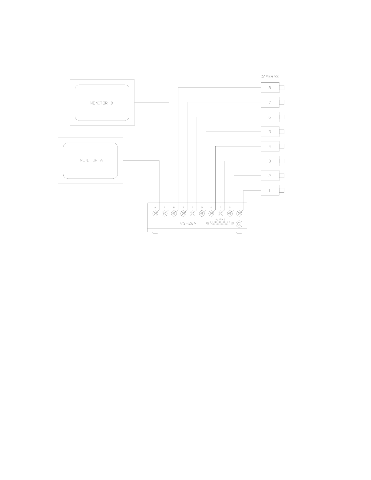
2. Getting Started
1/ Connect the switcher up as shown:
This diagram show the VS-28A. For other switchers, fewer camera inputs and
monitor outputs are available.
2/ Identify the 8 switches on the switcher which are visible thro ugh the cut-out in
the base of the unit near the front edge. Set all switches OFF except for
sections 1,2 and 3 which should ON (assuming 8 cameras).
3/ Switch ON the mains power. The switcher powers up in AUTO mode. Press a
camera select key to cancel the auto mode and view a partic ular camera.
Video Switch VST605C.DOC

VS Series 2 User Manual Page 4
3. Manual Switching
3.1 Selecting Manual Mode
Select manual mode for Monitor A by pressing the “AUTO A” switch to turn off its
LED, or any one of the Monitor A camera select keys (lower row).
The VS-28 and VS-28A switchers cater for a second monitor. Manual mode for the
Monitor B output may similar ly be selected by pressing the “AUTO B” switch to turn
off its LED, or any one of t he any one of the Monitor B camera select keys (middle
row).
3.2 Selecting Camera
Press one of the Monitor A camera select keys, identified 1,2,3,4,5,6,7 & 8 (lower
row) to display the required camera on Monitor A.
The VS-28 and VS-28A switchers cater for a second monitor. Press one of the
Monitor B camera select keys, identified 1,2,3,4,5,6,7 & 8 (upper row) to display the
required camera on Monitor B.
Video Switch VST605C.DOC
 Loading...