

Videoswitch VCM User Manual

Duplex Multiplexers User Manual Page 1
Videoswitch
Duplex Multiplexers
This manual covers the following Multiplexers:
Monochrome
VSM-24A 4 Camera Duplex Multiplexer (Desktop)
VSM-28A 8 Camera Duplex Multiplexer (Desktop)
VSM-24 4 Camera Duplex Multiplexer (Stackable)
VSM-28 8 Camera Duplex Multiplexer (Stackable)
VSM-212 12 Camera Duplex Multiplexer (Stackable)
VSM-216 16 Camera Duplex Multiplexer (Stackable)
VSM-220 20 Camera Duplex Multiplexer (Stackable)
Colour
VCM-24A 4 Camera Duplex Multiplexer (Desktop)
VCM-28A 8 Camera Duplex Multiplexer (Desktop)
VCM-24 4 Camera Duplex Multiplexer (Stackable)
VCM-28 8 Camera Duplex Multiplexer (Stackable)
VCM-212 12 Camera Duplex Multiplexer (Stackable)
VCM-216 16 Camera Duplex Multiplexer (Stackable)
VCM-220 20 Camera Duplex Multiplexer (Stackable)
Every effort has been made to ensur e the accu racy of the infor mation in this ma nual. Howe ver, Videosw itch
assumes no liability for losses incurred as a result of out of date information, errors or omissions. As part of
a policy of continual product improvement, Videoswitch reserves the right to make changes to product
specifications and documentation witho ut notice.
No reproduction of this document or any portion of it is permitted without the specific written permission of
Videoswitch.
This manual relates to multiplexers fitted with software Revision R3.01
Videoswitch is a trading division of Ocean Systems Ltd. ©Ocean Systems Ltd 1999.
Videoswitch Sales: 01252-851510
Unit 15 Redfields Industrial Park Other: 01252-851477
Church Crookham Fax: 01252-851296
Hants GU13 0RD Email: support@videoswitch.co.uk
____________________________________
Videoswitch VCM614d.doc
User Manual

Duplex Multiplexers User Manual Page 2
England Web: videoswitch.co.uk
____________________________________
Videoswitch VCM614d.doc

Duplex Multiplexers User Manual Page 3
Contents:
1. GETTING STARTED..........................................................................................................................................4
1.1 Step 1 - Connecting to Cameras, Monitors, VCR and Mains Supply ....................................................................................................................4
1.2 Step 2 - Step Cable ..................................................................................................................................................................................................4
1.3 Step 3 - Alarms........................................................................................................................................................................................................4
1.4 Step 4 - Identification of Switches..........................................................................................................................................................................5
1.5 Step 5 - Time-Lapse Mode Switch (S1)..................................................................................................................................................................5
1.6 Step 6 - Set-up Options Switch (S2) .......................................................................................................................................................................5
1.7 Step 7 - Camera Termination Switches (S3, S4, S5, S6 and S7)............................................................................................................................5
1.8 Step 8 - SET key options.........................................................................................................................................................................................5
2. OPERATION......................................................................................................................................................... 6
2.1 Record/Play Modes .................................................................................................................................................................................................6
2.2 VCR View Mode.....................................................................................................................................................................................................6
2.3 Display Options.......................................................................................................................................................................................................6
2.4 Auto-Sequence ........................................................................................................................................................................................................7
2.5 System Testing ........................................................................................................................................................................................................7
3. SWITCH OPTIONS.............................................................................................................................................8
3.1 Time Lapse Mode Switch (rotary) - with a Step Cable...........................................................................................................................................8
3.2 Time Lapse Mode Switch (rotary) - without a Step Cable......................................................................................................................................9
3.3 Set-up Switch (8-way DIL) ...................................................................................................................................................................................10
3.4 Camera Termination Switches (4-way DIL).........................................................................................................................................................10
3.5 Interface Connector Pin-out (25-way D-type) ......................................................................................................................................................11
3.6 RS232 Connector Pin-out (3.5mm Jack)...............................................................................................................................................................11
4. SET KEY OPTIONS................... ......................... ............................................................................................... 12
4.1 Auto Sequence Dwell Time (Full Screen) ............................................................................................................................................................12
4.2 Auto Sequence Dwell Time (Quad Screen) ..........................................................................................................................................................12
4.3 Auto Sequence Camera Selection .........................................................................................................................................................................12
4.4 Auto Sequence Quad Selection.............................................................................................................................................................................12
4.5 Alarm Hold Time...................................................................................................................................................................................................12
4.6 Alarm Sequence Dwell Time ................................................................................................................................................................................12
4.7 Alarm Relay Hold Time ........................................................................................................................................................................................12
4.8 Covert Cameras .....................................................................................................................................................................................................12
4.9 Temporarily Disable Alarms .................................................................................................................................................................................13
4.10 Quad and Multi Screen Video Interlace Selection..............................................................................................................................................13
4.11 User Defined Record Interval .............................................................................................................................................................................13
4.12 Factory-Set Defaults............................................................................................................................................................................................13
5. TROUBLE-SHOOTING.................................................................................................................................... 14
5.1 Things to check......................................................................................................................................................................................................14
5.2 No Images in Record mode ...................................................................................................................................................................................14
5.3 Missing Images in Record mode...........................................................................................................................................................................14
5.4 Missing Cameras in Auto Sequence......................................................................................................................................................................14
5.5 Washed Out Images...............................................................................................................................................................................................14
5.6 Dark Images...........................................................................................................................................................................................................14
5.7 Flashing Images.....................................................................................................................................................................................................14
5.8 No Images in Play mode........................................................................................................................................................................................14
5.9 Missing Images in Play mode................................................................................................................................................................................14
6. SPECIFICATIONS.............................................................................................................................................15
6.1 Resolution..............................................................................................................................................................................................................15
6.2 Dwell Times...........................................................................................................................................................................................................15
6.3 Video Inputs and Outputs......................................................................................................................................................................................15
6.4 VCR “STEP” Input................................................................................................................................................................................................15
6.5 Alarms....................................................................................................................................................................................................................15
6.6 RS232 ....................................................................................................................................................................................................................15
6.7 Power Requirements..............................................................................................................................................................................................15
6.8 Physical and Environmental..................................................................................................................................................................................15
7. SAFETY WARNING............................................................. ............................................................................. 16
____________________________________
Videoswitch VCM614d.doc
Duplex Multiplexers User Manual Page 4
1. Getting Started
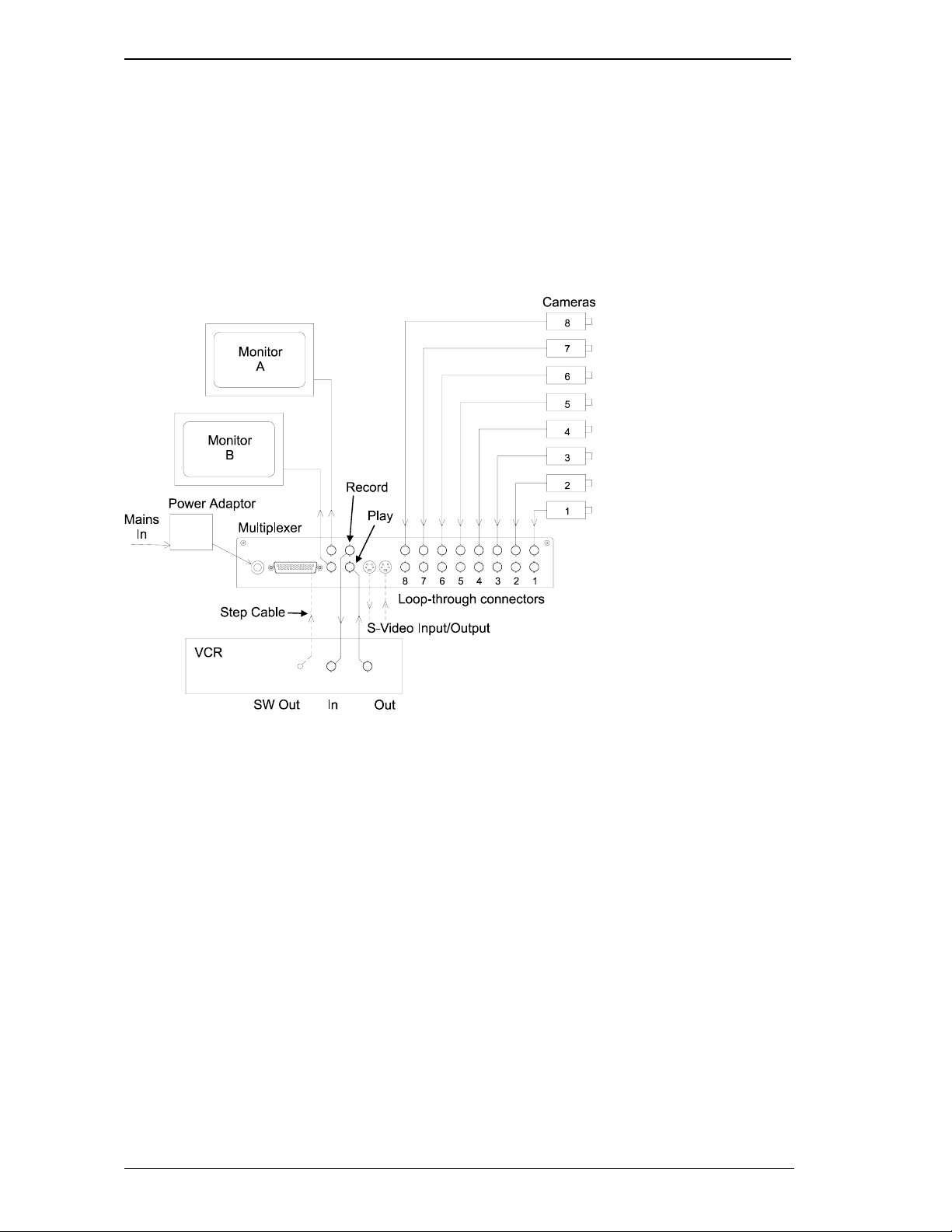
1.1 Step 1 - Connecting to Cameras, Monitors, VCR and Mains Supply
Connect the multiplexer to the cameras, monitor(s), VCR and mains supply as illustrated in this
diagram.
Note that an 8-camera multiplexer is used in this example. Other multiplexers differ in the number
and location of the connectors.
Each camera input is provided with two BNC connectors. This allows cameras to be loopedthrough to other equipment. Either connector may be used for input or output.
Note: This is an example only. Refer to the rear panel labelling for specific locations of connectors.
Desktop models do not have loop-through.
1.2 Step 2 - Step Cable
If a step cable is required, connect it between the multiplexer and the VCR as in the diagram above.
Refer to section 3.1 and section 3.2 for details.
1.3 Step 3 - Alarms
If alarms are required, connect these in accordance with the details in section 3.5.
____________________________________
Videoswitch VCM614d.doc

Duplex Multiplexers User Manual Page 5
1.4 Step 4 - Identification of Switches
Identify where the switches are on the underside of the multiplexer as illustrated in this diagram.
A 20-camera multiplexer is used in this example. Other models are similar but have fewer
termination switches.
1.5 Step 5 - Time-Lapse Mode Swi t ch ( S1)
Set this switch to suit the time lapse mode of the VCR or to specify whether a step cable is being
used. For example, set to position 4 for 24 time-lapse operation without a step cable. Refer to
section 3.1 and section 3.2 for details.
1.6 Step 6 - Set-up Options Switch (S2)
Set this switch to specify the basic set-up options. In most installations, the default setting of all
sections OFF, will be required. Refer to section 3.3 for details.
1.7 Step 7 - Camera Termination Switches (S3, S4, S5, S6 and S7)
Set these switches ON if camera termination is required. In most installations the default setting of
all sections ON will be required. Refer to section 3.4 for details.
1.8 Step 8 - SET key options
Further options are available by using the SET key in combination with other keys. In many cases it
is not necessary to access these facilities. Refer to section 4 for details.
____________________________________
Videoswitch VCM614d.doc
 Loading...