

Videoswitch CMOR-D18? CMOR-D26 User Manual
CMOR
Professional Dome
User Manual
Product ranges covered by this manual
CMOR-D18 & CMOR-D26
Professional Dome
CMOR-PSU-1
Document Reference
Vc601e.doc 18/02/2009 From Vc001A82
Date Firmware
Videoswitch
Ocean House, Redfields Industrial Park Fax 01252-851296
Redfields Lane, Church Crookham Email sales@videoswitch.co.uk
Hants GU52 0RD Web www.videoswitch.co.uk
CMOR-ALM-16 Options
Telephone 01252-851510
Page 1

Configuring the Dome....................................................4
1.1 Removing the DIP switch cover.............................................................................................4
1.2 Setting the dome address......................................................................................................5
1.3 Setting the dome protocol....................................................................................................10
1.4 Setting the baud rate............................................................................................................10
1.5 Setting the RS485 termination.............................................................................................11
1.6 Replacing the DIP switch cover...........................................................................................11
2 Installing the Dome ................................................13
2.1 Fixing the mounting ring.......................................................................................................13
2.2 Securing the bracket............................................................................................................14
2.3 Attaching the CMOR Dome .................................................................................................15
2.4 Attaching the umbilical cable ...............................................................................................15
2.5 Fitting the bracket cover.......................................................................................................16
3 Installing Power Supply.........................................17
3.1 Fixing power supply to wall..................................................................................................17
3.2 Power Supply Connections..................................................................................................18
3.2.1 Mains Input ......................................................................................................................18
3.2.2 Connections to dome.......................................................................................................18
3.2.3 Connections to DVR ........................................................................................................19
3.3 Alarm Module Connections..................................................................................................20
3.3.1 Alarm Inputs.....................................................................................................................20
3.3.2 Alarm Grounds.................................................................................................................20
3.3.3 Relay Connections...........................................................................................................20
4 Configuring the Alarm Module..............................21
4.1 Normally Open or Closed Alarm Inputs ...............................................................................21
4.2 RS485 Termination..............................................................................................................21
4.3 Setting the alarm module protocol .......................................................................................21
4.4 Setting the alarm module baud rate.....................................................................................22
5 Menus......................................................................23
5.1 Menu Navigation..................................................................................................................23
5.1.1 Entering Menu..................................................................................................................23
5.1.2 Moving cursor ..................................................................................................................23
5.1.3 Select...............................................................................................................................23
5.1.4 Cancel..............................................................................................................................23
5.1.5 Exit Menu.........................................................................................................................24
5.2 Login ....................................................................................................................................24
5.3 Setup....................................................................................................................................25
5.3.1 Enter date/time.................................................................................................................25
5.3.2 Daylight Saving................................................................................................................25
5.3.3 Language.........................................................................................................................25
5.3.4 Display.............................................................................................................................25
5.3.5 Passwords .......................................................................................................................25
5.3.6 Datum Check ...................................................................................................................26
5.3.7 Install date/time................................................................................................................26
5.3.8 Clear Settings ..................................................................................................................26
5.4 IR..........................................................................................................................................27
Page 2

5.4.1 IR Mode ...........................................................................................................................27
5.4.2 IR ON level.......................................................................................................................27
5.4.3 IR Off level hysteretic.......................................................................................................27
5.4.4 Auto IR delay ...................................................................................................................27
5.4.5 IR ON times .....................................................................................................................27
5.4.6 IR Power ..........................................................................................................................27
5.5 Camera ................................................................................................................................28
5.5.1 Main camera settings.......................................................................................................28
5.5.2 Context Camera...............................................................................................................29
5.5.3 Invert Image.....................................................................................................................29
5.6 Keyboard..............................................................................................................................29
5.6.1 Restore Mode (Preset & Tours).......................................................................................29
5.6.2 Restore delay (Preset & Tours) .......................................................................................29
5.6.3 Joystick/Speed Curve......................................................................................................29
5.6.4 Zoom Ratio ......................................................................................................................30
5.6.5 Max Joystick Speed.........................................................................................................30
5.6.6 Pan Limits........................................................................................................................30
5.6.7 Iris key usage...................................................................................................................30
5.7 Presets.................................................................................................................................30
5.7.1 Set Preset........................................................................................................................30
5.7.2 Preset Titles.....................................................................................................................30
5.7.3 Preset Speed...................................................................................................................31
5.8 Tours....................................................................................................................................31
5.9 Privacy .................................................................................................................................32
5.10 Alarms..................................................................................................................................32
5.10.1 New alarm dwell...............................................................................................................32
5.10.2 Alarm cycle time...............................................................................................................32
6 Technical Data........................................................33
6.1 CMOR-D18 Dome................................................................................................................33
6.1.1 Camera ............................................................................................................................33
6.1.2 IR Illumination..................................................................................................................33
6.1.3 Power requirements.........................................................................................................33
6.1.4 Physical and Environmental.............................................................................................33
6.2 CMOR-PSU-1 Power Supply...............................................................................................33
6.2.1 Power requirements.........................................................................................................33
6.2.2 Physical and Environmental.............................................................................................33
6.2.3 Safety...............................................................................................................................33
6.3 CMOR-ALM-16 Alarm Module.............................................................................................34
6.3.1 Alarm Inputs/Outputs .......................................................................................................34
6.3.2 Physical and Environmental.............................................................................................34
6.4 Brackets and Cables............................................................................................................34
6.4.1 Wall bracket.....................................................................................................................34
6.4.2 Corner adaptor.................................................................................................................34
6.4.3 Swan-neck bracket ..........................................................................................................34
6.4.4 Pendant bracket...............................................................................................................34
6.4.5 Cables..............................................................................................................................34
6.5 CE Marking ..........................................................................................................................34
Page 3

Configuring the Dome
The CMOR dome is supplied with DIP switches set for the following configuration:
Twisted pair: Addres s: 1
Protocol: Videoswitch VXP4
Baud rate: 9600 baud,
Termination: ON
Up-the-coax: BBV compatible
Dome
Address
1 1 0 0 0 0 0 0 0
Protocol, baud, termination
VXP4&Coax/9600 baud/On 0 0 0 0 0 1
8-way DIP switch
1 2 3 4 5 6 7 8
6-way DIP switch
1 23456
1.1 Removing the DIP switch cover
If you need to change DIP switch settings, you may do so either before or after the dome is
mounted on its bracket, whichever is more convenient.
• Using a large flat bladed screwdriver, unscrew the DIP switch access screw (A) on
the rear of the dome by turning counter-clockwise
Page 4
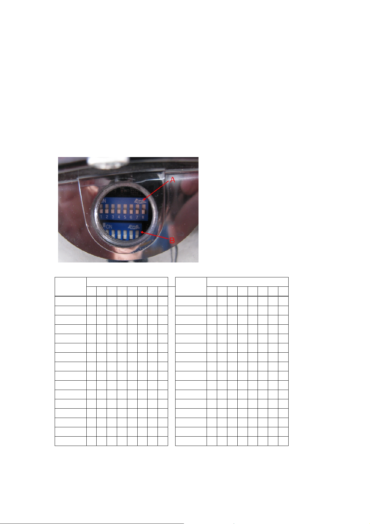
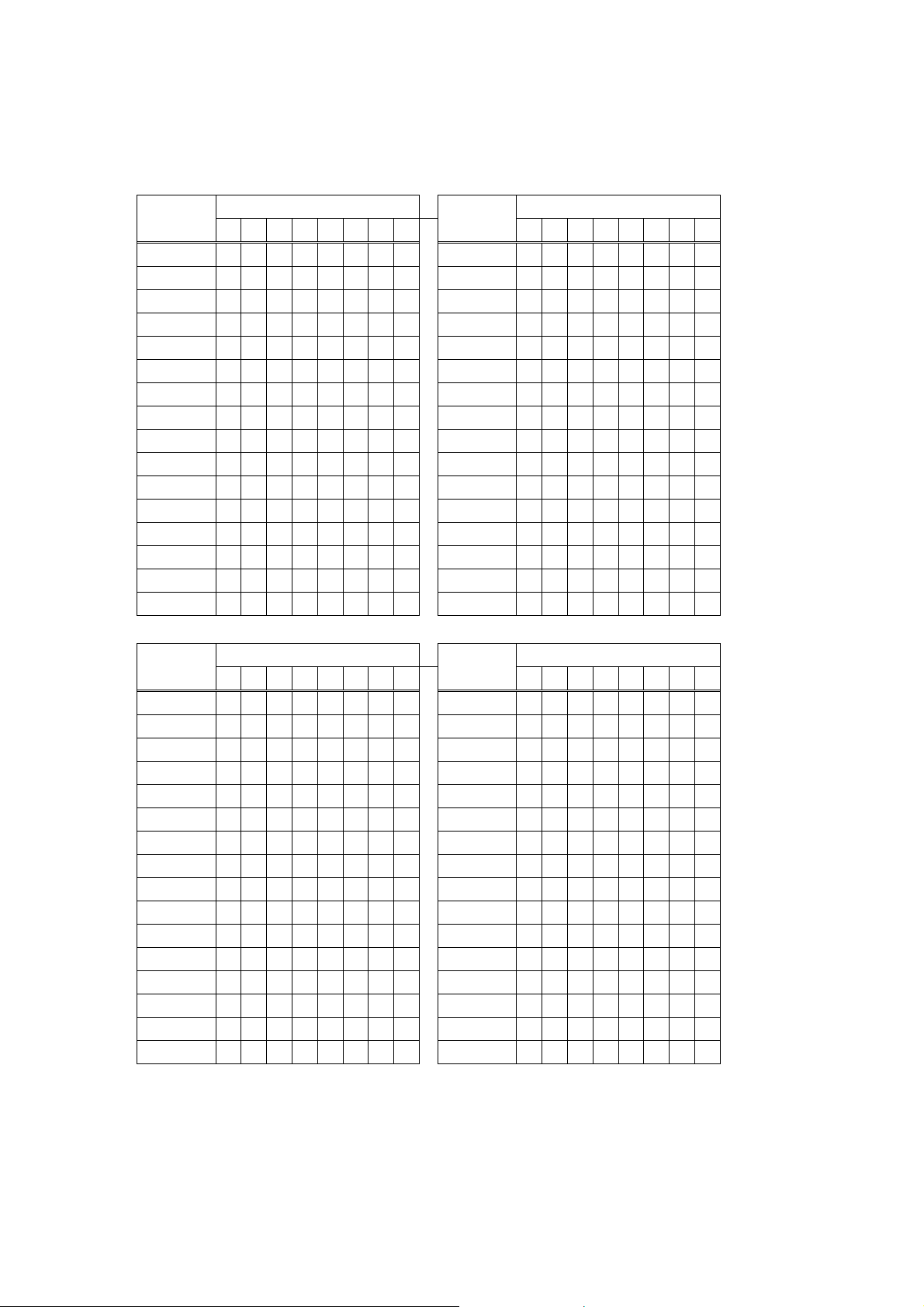
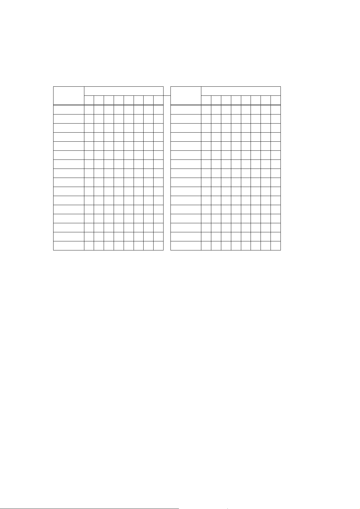
1.2 Setting the dome address
• Set the 8-way switch (A) to the required address (camera number) of the dome as
per the table below. “0” represents OFF (down) and “1” represents ON (up).
Dome
Address
not used 0 0 0 0 0 0 0 0 16 0 0 0 0 1 0 0 0
1 1 0 0 0 0 0 0 0 17 1 0 0 0 1 0 0 0
2 0 1 0 0 0 0 0 0 18 0 1 0 0 1 0 0 0
3 1 1 0 0 0 0 0 0 19 1 1 0 0 1 0 0 0
4 0 0 1 0 0 0 0 0 20 0 0 1 0 1 0 0 0
5 1 0 1 0 0 0 0 0 21 1 0 1 0 1 0 0 0
6 0 1 1 0 0 0 0 0 22 0 1 1 0 1 0 0 0
7 1 1 1 0 0 0 0 0 23 1 1 1 0 1 0 0 0
8 0 0 0 1 0 0 0 0 24 0 0 0 1 1 0 0 0
9 1 0 0 1 0 0 0 0 25 1 0 0 1 1 0 0 0
10 0 1 0 1 0 0 0 0 26 0 1 0 1 1 0 0 0
11 1 1 0 1 0 0 0 0 27 1 1 0 1 1 0 0 0
12 0 0 1 1 0 0 0 0 28 0 0 1 1 1 0 0 0
13 1 0 1 1 0 0 0 0 29 1 0 1 1 1 0 0 0
14 0 1 1 1 0 0 0 0 30 0 1 1 1 1 0 0 0
15 1 1 1 1 0 0 0 0 31 1 1 1 1 1 0 0 0
8-way DIP switch 8-way DIP switch
1 2 3 4 5 6 7 8
Dome
Address
123456 7 8
Page 5
Dome
Address
8-way DIP switch 8-way DIP switch
1 2 3 4 5 6 7 8
Dome
Address
123456 7 8
32 0 0 0 0 0 1 0 0 48 0 0 0 0 1 1 0 0
33 1 0 0 0 0 1 0 0 49 1 0 0 0 1 1 0 0
34 0 1 0 0 0 1 0 0 50 0 1 0 0 1 1 0 0
35 1 1 0 0 0 1 0 0 51 1 1 0 0 1 1 0 0
36 0 0 1 0 0 1 0 0 52 0 0 1 0 1 1 0 0
37 1 0 1 0 0 1 0 0 53 1 0 1 0 1 1 0 0
38 0 1 1 0 0 1 0 0 54 0 1 1 0 1 1 0 0
39 1 1 1 0 0 1 0 0 55 1 1 1 0 1 1 0 0
40 0 0 0 1 0 1 0 0 56 0 0 0 1 1 1 0 0
41 1 0 0 1 0 1 0 0 57 1 0 0 1 1 1 0 0
42 0 1 0 1 0 1 0 0 58 0 1 0 1 1 1 0 0
43 1 1 0 1 0 1 0 0 59 1 1 0 1 1 1 0 0
44 0 0 1 1 0 1 0 0 60 0 0 1 1 1 1 0 0
45 1 0 1 1 0 1 0 0 61 1 0 1 1 1 1 0 0
46 0 1 1 1 0 1 0 0 62 0 1 1 1 1 1 0 0
47 1 1 1 1 0 1 0 0 63 1 1 1 1 1 1 0 0
Dome
Address
8-way DIP switch 8-way DIP switch
1 2 3 4 5 6 7 8
Dome
Address
123456 7 8
64 0 0 0 0 0 0 1 0 80 0 0 0 0 1 0 1 0
65 1 0 0 0 0 0 1 0 81 1 0 0 0 1 0 1 0
66 0 1 0 0 0 0 1 0 82 0 1 0 0 1 0 1 0
67 1 1 0 0 0 0 1 0 83 1 1 0 0 1 0 1 0
68 0 0 1 0 0 0 1 0 84 0 0 1 0 1 0 1 0
69 1 0 1 0 0 0 1 0 85 1 0 1 0 1 0 1 0
70 0 1 1 0 0 0 1 0 86 0 1 1 0 1 0 1 0
71 1 1 1 0 0 0 1 0 87 1 1 1 0 1 0 1 0
72 0 0 0 1 0 0 1 0 88 0 0 0 1 1 0 1 0
73 1 0 0 1 0 0 1 0 89 1 0 0 1 1 0 1 0
74 0 1 0 1 0 0 1 0 90 0 1 0 1 1 0 1 0
75 1 1 0 1 0 0 1 0 91 1 1 0 1 1 0 1 0
76 0 0 1 1 0 0 1 0 92 0 0 1 1 1 0 1 0
77 1 0 1 1 0 0 1 0 93 1 0 1 1 1 0 1 0
78 0 1 1 1 0 0 1 0 94 0 1 1 1 1 0 1 0
79 1 1 1 1 0 0 1 0 95 1 1 1 1 1 0 1 0
Page 6

Dome
Address
8-way DIP switch 8-way DIP switch
1 2 3 4 5 6 7 8
Dome
Address
123456 7 8
96 0 0 0 0 0 1 1 0 112 0 0 0 0 1 1 1 0
97 1 0 0 0 0 1 1 0 113 1 0 0 0 1 1 1 0
98 0 1 0 0 0 1 1 0 114 0 1 0 0 1 1 1 0
99 1 1 0 0 0 1 1 0 115 1 1 0 0 1 1 1 0
100 0 0 1 0 0 1 1 0 116 0 0 1 0 1 1 1 0
101 1 0 1 0 0 1 1 0 117 1 0 1 0 1 1 1 0
102 0 1 1 0 0 1 1 0 118 0 1 1 0 1 1 1 0
103 1 1 1 0 0 1 1 0 119 1 1 1 0 1 1 1 0
104 0 0 0 1 0 1 1 0 120 0 0 0 1 1 1 1 0
105 1 0 0 1 0 1 1 0 121 1 0 0 1 1 1 1 0
106 0 1 0 1 0 1 1 0 122 0 1 0 1 1 1 1 0
107 1 1 0 1 0 1 1 0 123 1 1 0 1 1 1 1 0
108 0 0 1 1 0 1 1 0 124 0 0 1 1 1 1 1 0
109 1 0 1 1 0 1 1 0 125 1 0 1 1 1 1 1 0
110 0 1 1 1 0 1 1 0 126 0 1 1 1 1 1 1 0
111 1 1 1 1 0 1 1 0 127 1 1 1 1 1 1 1 0
Dome
Address
8-way DIP switch 8-way DIP switch
1 2 3 4 5 6 7 8
Dome
Address
123456 7 8
128 0 0 0 0 0 0 0 1 144 0 0 0 0 1 0 0 1
129 1 0 0 0 0 0 0 1 145 1 0 0 0 1 0 0 1
130 0 1 0 0 0 0 0 1 146 0 1 0 0 1 0 0 1
131 1 1 0 0 0 0 0 1 147 1 1 0 0 1 0 0 1
132 0 0 1 0 0 0 0 1 148 0 0 1 0 1 0 0 1
133 1 0 1 0 0 0 0 1 149 1 0 1 0 1 0 0 1
134 0 1 1 0 0 0 0 1 150 0 1 1 0 1 0 0 1
135 1 1 1 0 0 0 0 1 151 1 1 1 0 1 0 0 1
136 0 0 0 1 0 0 0 1 152 0 0 0 1 1 0 0 1
137 1 0 0 1 0 0 0 1 153 1 0 0 1 1 0 0 1
138 0 1 0 1 0 0 0 1 154 0 1 0 1 1 0 0 1
139 1 1 0 1 0 0 0 1 155 1 1 0 1 1 0 0 1
140 0 0 1 1 0 0 0 1 156 0 0 1 1 1 0 0 1
141 1 0 1 1 0 0 0 1 157 1 0 1 1 1 0 0 1
142 0 1 1 1 0 0 0 1 158 0 1 1 1 1 0 0 1
143 1 1 1 1 0 0 0 1 159 1 1 1 1 1 0 0 1
Page 7

Dome
Address
8-way DIP switch 8-way DIP switch
1 2 3 4 5 6 7 8
Dome
Address
123456 7 8
160 0 0 0 0 0 1 0 1 176 0 0 0 0 1 1 0 1
161 1 0 0 0 0 1 0 1 177 1 0 0 0 1 1 0 1
162 0 1 0 0 0 1 0 1 178 0 1 0 0 1 1 0 1
163 1 1 0 0 0 1 0 1 179 1 1 0 0 1 1 0 1
164 0 0 1 0 0 1 0 1 180 0 0 1 0 1 1 0 1
165 1 0 1 0 0 1 0 1 181 1 0 1 0 1 1 0 1
166 0 1 1 0 0 1 0 1 182 0 1 1 0 1 1 0 1
167 1 1 1 0 0 1 0 1 183 1 1 1 0 1 1 0 1
168 0 0 0 1 0 1 0 1 184 0 0 0 1 1 1 0 1
169 1 0 0 1 0 1 0 1 185 1 0 0 1 1 1 0 1
170 0 1 0 1 0 1 0 1 186 0 1 0 1 1 1 0 1
171 1 1 0 1 0 1 0 1 187 1 1 0 1 1 1 0 1
172 0 0 1 1 0 1 0 1 188 0 0 1 1 1 1 0 1
173 1 0 1 1 0 1 0 1 189 1 0 1 1 1 1 0 1
174 0 1 1 1 0 1 0 1 190 0 1 1 1 1 1 0 1
175 1 1 1 1 0 1 0 1 191 1 1 1 1 1 1 0 1
Dome
Address
8-way DIP switch 8-way DIP switch
1 2 3 4 5 6 7 8
Dome
Address
123456 7 8
192 0 0 0 0 0 0 1 1 208 0 0 0 0 1 0 1 1
193 1 0 0 0 0 0 1 1 209 1 0 0 0 1 0 1 1
194 0 1 0 0 0 0 1 1 210 0 1 0 0 1 0 1 1
195 1 1 0 0 0 0 1 1 211 1 1 0 0 1 0 1 1
196 0 0 1 0 0 0 1 1 212 0 0 1 0 1 0 1 1
197 1 0 1 0 0 0 1 1 213 1 0 1 0 1 0 1 1
198 0 1 1 0 0 0 1 1 214 0 1 1 0 1 0 1 1
199 1 1 1 0 0 0 1 1 215 1 1 1 0 1 0 1 1
200 0 0 0 1 0 0 1 1 216 0 0 0 1 1 0 1 1
201 1 0 0 1 0 0 1 1 217 1 0 0 1 1 0 1 1
202 0 1 0 1 0 0 1 1 218 0 1 0 1 1 0 1 1
203 1 1 0 1 0 0 1 1 219 1 1 0 1 1 0 1 1
204 0 0 1 1 0 0 1 1 220 0 0 1 1 1 0 1 1
205 1 0 1 1 0 0 1 1 221 1 0 1 1 1 0 1 1
206 0 1 1 1 0 0 1 1 222 0 1 1 1 1 0 1 1
207 1 1 1 1 0 0 1 1 223 1 1 1 1 1 0 1 1
Page 8
Dome
Address
8-way DIP switch 8-way DIP switch
1 2 3 4 5 6 7 8
Dome
Address
123456 7 8
224 0 0 0 0 0 1 1 1 240 0 0 0 0 1 1 1 1
225 1 0 0 0 0 1 1 1 241 1 0 0 0 1 1 1 1
226 0 1 0 0 0 1 1 1 242 0 1 0 0 1 1 1 1
227 1 1 0 0 0 1 1 1 243 1 1 0 0 1 1 1 1
228 0 0 1 0 0 1 1 1 244 0 0 1 0 1 1 1 1
229 1 0 1 0 0 1 1 1 245 1 0 1 0 1 1 1 1
230 0 1 1 0 0 1 1 1 246 0 1 1 0 1 1 1 1
231 1 1 1 0 0 1 1 1 247 1 1 1 0 1 1 1 1
232 0 0 0 1 0 1 1 1 248 0 0 0 1 1 1 1 1
233 1 0 0 1 0 1 1 1 249 1 0 0 1 1 1 1 1
234 0 1 0 1 0 1 1 1 250 0 1 0 1 1 1 1 1
235 1 1 0 1 0 1 1 1 251 1 1 0 1 1 1 1 1
236 0 0 1 1 0 1 1 1 252 0 0 1 1 1 1 1 1
237 1 0 1 1 0 1 1 1 253 1 0 1 1 1 1 1 1
238 0 1 1 1 0 1 1 1 254 0 1 1 1 1 1 1 1
239 1 1 1 1 0 1 1 1 255 1 1 1 1 1 1 1 1
Page 9
1.3 Setting the dome protocol
• Set sections 1,2 and 3 of the 6-way switch (B) as per the table below to select the
required protocol. “0” represents OFF (down) and “1” repre sents ON (up).
Protocol 1 2 3
Videoswitch VXP4 and BBV up-the-coax 0 0 0
Videoswitch VXP4 only 1 0 0
PelcoP 0 1 0
PelcoD 1 1 0
spare 0 0 1
spare 1 0 1
spare 0 1 1
spare 1 1 1
If coax telemetry is not being used, a protocol other than the first one should be selected to
minimise the possibility of spurious commands being received.
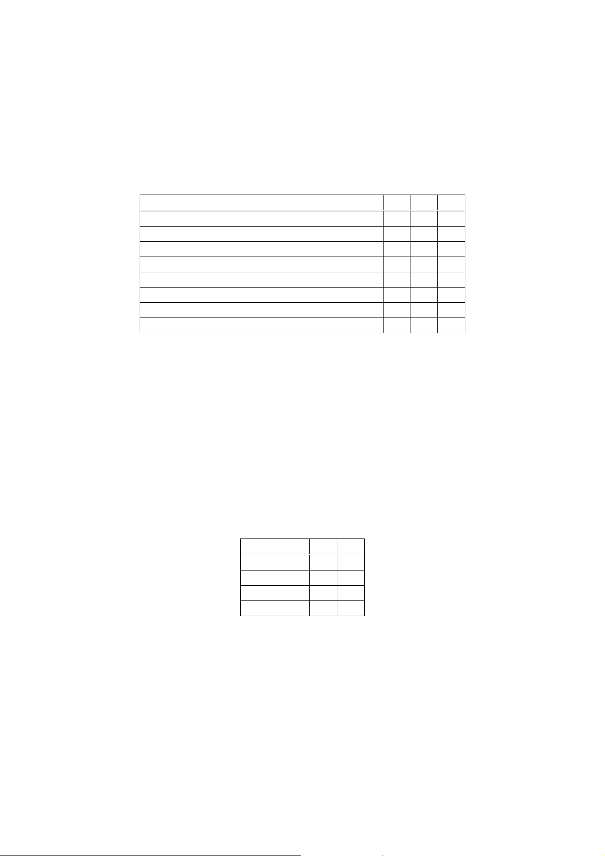
1.4 Setting the baud rate
• Set sections 4 and 5 of the 6-way switch (B) as per the table below to select the
required baud rate. “0” represents OFF (down) and “1” represents ON (up).
• The default setting is 9600 baud (both switches OFF)
• PelcoD normally uses 2400 baud
• PelcoP normally uses 4800 baud
Baud rate 4 5
9600 0 0
2400 1 0
4800 0 1
19200 1 1
Page 10

1.5 Setting the RS485 termination
Set section 6 of the 6-way switch (B) as per the table below to select the termination of the
RS485 twisted pair input. “0” represents OFF (down) and“1” represents ON (up). The default
position in ON (up).
Termination 6
OFF 0
ON 1
The termination switch should be ON if:
• The dome is the only one connected to the twisted pair
• The dome is the last one of several domes connected to the twisted pair
• An alarm module is fitted into the dome power supply
The termination switch should be OFF if:
• More than one dome is connected to the twisted pair and the dome is not the last in
the line.
1.6 Replacing the DIP switch cover
• Replace the DIP switch access screw (A) on the rear of the dome
• Take care that the thread is correctly aligned, that there is no dirt or grit that could
affect the waterproof seal.
• Using a large flat bladed screwdriver turn clockwise to secure the screw.
• Do not over-tighten.
Page 11
 Loading...