

Video Storm CMX1616A2 Owner's Manual

Model CMX1616A2
AV Matrix Switch with DSP audio
(firmware 1.0)
Overview:
This product is a full featured video & audio matrix switch. It is most commonly used to independently
distribute video & audio to several different viewing areas from a set of common sources. CMX1616A2
provides 16 audio output zones from 16 audio common sources. It also provides 8 video output zones from
8 video common sources.
The matrix switch has 3 control modes to choose from:
Manual control from the front buttons
IR control by remote control
Serial control via the RS-232 port (db9).
Unit includes
CMX1616A2 matrix switch
Owners manual
12V desktop power supply
3 year parts and labor warranty
Optional rack mounting ears & screws
Warranty
Video Storm LLC products are covered by our manufacture’s warranty. Our warranty covers parts and
labor for 3 years following purchase. In the unlikely event you receive an item that was not damaged in
shipping but is defective please contact support@video-storm.com and we will repair or replace the item
promptly.

Installation
Please use the following steps to install and set up your CMX1616A2.
When looking at the rear of the CMX1616A2, all inputs are on the left half and all outputs are on the right
half.
1. Analog audio: Connect the analog stereo audio sources to the input red/white RCA jacks marked
1-16. Connect the output cables to the output red/white RCA jacks marked 1-16. Be sure to
match the cable colors to RCA jack color.
2. Composite video: Connect the composite video sources to the input yellow RCA jacks marked 1-
8. Connect the output cables to the output yellow RCA jacks marked 1-8. Note that there are 2
different sets of yellow RCA jacks. The jacks near the TOSLINK connectors are composite
video.
3. Digital coax audio: Connect the digital audio sources to the yellow RCA jacks marked 1-16.
Connect the output cables to the output yellow RCA jacks marked 1-16. Note that there are 2
different sets of yellow RCA jacks. The jacks next to the red/white jacks are digital audio coax.
4. Digital TOSLINK audio: Connect the digital audio sources to the input TOSLINK jacks marked
1-6. Connect the output cables to the output TOSLINKS jacks marked 1-6.
5. RS-232: If needed, connect your computer or controller to the DB9 jack labeled “Control” using a
DB9 male to female normal modem cable.
6. RS-232 expansion: If using a HMX HDMI matrix, connect a DB9 male to female normal modem
cable from the RS-232 jack labeled “XP” to the RS-232 jack on the HMX matrix.
7. Connect the supplied wall transformer to a properly grounded power outlet. Plug into DC input of
the CMX1616A2.
8. Press one of the front panel buttons; you should see the LED display turn on.
Controlling the CMX1616A2
The CMX1616A2 can be controlled by 3 methods: front panel switch, infrared remote, or RS-232 serial.
You may use any or all methods in any combination. All methods can access all features and modes.
The left front panel button controls the output selection (left two LED digits). Each press will cycle
through the available outputs. The right button controls the input selection (right two LED digits). Each
press will cycle through the available inputs. Pressing and holding the left button for 3 or more seconds
will jump the output selection to the next connector type when released. Pressing and holding the right
button for 3 or more seconds is only used in Zerokey programming mode, config mode, for volume mute
toggle or for quick select mode.
NOTE: Output needs to be selected before setting the input.
Quick select can be used to easily send a single input to all outputs. To use quick select, simply select
output 1 using the left button, toggle to the input desired using the right button, and then press and hold the
right button for 3 or more seconds.
Flash modes allow the user to save and later recall up to 8 different switch setups. Flash modes are saved
to flash memory, so are unaffected by power cycling. To use the flash modes, select “Fx” (x is 1-8) using
the left button (or IR). The right LED will display “E” if no saved mode exists in this slot, otherwise “F”.
Use a short press with the right button to recall these settings. Use a long press with the right button to save
the current switch setup to this flash slot. When using IR, the sequence is (Output type select “F”, input
select 0-15). Use input select codes 0-7 to recall flash modes 1-8, and input select codes 8-15 to save to
flash modes 1-8.
The IR remote and RS-232 interface can select outputs and inputs directly. If using the RS-232 interface,
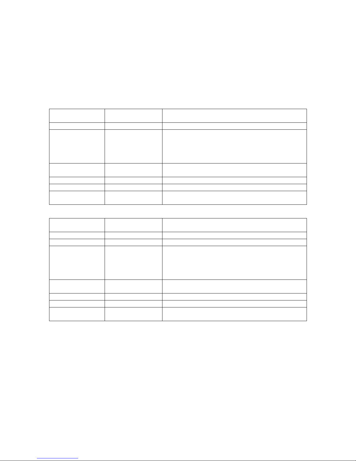
Left LED Display
(selected output)
Right LED Display
(selected input)
Description
A 1-16
0-16
Control for all outputs types
G 1-38
0-16
Volume control for audio outputs. G1-16 is analog audio.
G17-32 is digital coax. G33-38 is TOSLINK. The right
display is the volume, “00” is min while “16” is max
volume.
A “.” After the number indicates MUTE is ON
F 1-8
E/F
Flash mode slot 1-8. If right LED shows E, then slot is
empty. If right LED shows F, then slot is active.
CF
C-U , O/F
Config menu, please see setting below
SZ
0-40
Zerokey programming mode, please see Zerokey section
SU
00
Audio menu, press hold right button for 6 seconds to enter
audio menu
Left LED Display
(selected output)
Right LED Display
(selected input)
Description
A 1-16
0-16
Analog audio control.
P 1-8
0-8
Composite video control
G 1-38
0-16
Volume control for audio outputs. G1-16 is analog audio.
G17-32 is digital coax. G33-38 is TOSLINK. The right
display is the volume, “00” is min while “16” is max
volume.
A “.” After the number indicates MUTE is ON
F 1-8
E/F
Flash mode slot 1-8. If right LED shows E, then slot is
empty. If right LED shows F, then slot is active.
CF
C-U, O/F
Config menu, please see setting below
SZ
0-41
Zerokey programming mode, please see Zerokey section
SU
00
Audio menu, press hold right button for 6 seconds to enter
audio menu
please refer to the programming guide on our web site. The IR interface is explained later in this
document.
The table below explains what the LED displays indicate. Note that generally the left two digits display the
selected output and the right two digits display the selected input. When selecting an output greater than 9,
the letter will flash for 1 second and then the “1” will be displayed. When “0” is displayed as the selected
input that output is powered off.
Basic mode
Advanced mode
Right LED display for configuration menu:
1. C Clear memory. Press the right front panel key and hold for 6 seconds to reset all Zerokey IR
codes to factory defaults and put the switch into basic mode.
2. L LED OFF. Press and hold the right switch to black out the LED display. Any button will restore.
3. P Power OFF. Press and hold the right switch to turn off CMX1616A2. Any button will restore
power.
4. U O/F Controls basic or advanced mode selection. Press & hold the right switch to turn on/off .
F means basic mode, O means advanced mode.
5. 1 O/F Not used
6. 2 O/F Not used
7. 3 O/F Power up default. When this control is switched from F to O, it will save the current state
of all outputs to flash memory. At power up if this control is O, the saved state will be loaded at power
up. If it is F, all outputs will be disabled on power up.
 Loading...