

Video Server 4 Ch Video Sever User Manual
1/34
User Manual
4 Ch Video Sever
V1.1_110614
2/34
WARINGS
TO REDUCE THE RISK OF FIRE OR ELECTRIC SHOCK, DO NOT EXPOSE THIS
PRODUCT TO RAIN OR MOISTURE.
DO NOT INSERT ANY METALLIC & ELETRIC CONDUCTIVE OBJECT THROUGH
VENTILATION GRILLS.
CAUTION
CAUTION
RISK OF ELECTRIC SHOCK
DO NOT OPEN
CAUTION:TO REDUCE THE RISK OF ELECTRIC SHOCK.
DO NOT REMOVE COVER (OR BACK).
NO USER-SERVICEABLE PARTS INSIDE.
REFER SERVICING TO QUALIFIED SERVICE PERSONNEL.
COPYRIGHT
THE TRADEMARKS MENTIONED IN THE MANUAL ARE LEGALLY REGISTERED
TO THEIR RESPECTIVE COMPANIES.

3/34
Content
I. PREFACE ..................................................................................................................................................... 4
II. PRODUCT SPECIFICATIONS ................................................................................................................. 4
III. PRODUCT INSTALLATION ................................................................................................ ..................... 6
A. MONITOR SETTING ..................................................................................................................................... 6
B. HARDWARE INSTALLATION ........................................................................................................................ 7
C. IP ASSIGNMENT ....................................................................................................................................... 10
D. INSTALL ACTIVEX CONTROL (SETUP ONCE ONLY): ................................................................................... 13
IV. LIVE VIDEO .............................................................................................................................................. 15
V. VIDEO SERVER CONFIGURATION .................................................................................................... 17
A. SYSTEM.................................................................................................................................................... 18
B. NETWORK ................................................................................................................................................ 21
C. MULTIMEDIA ............................................................................................................................................ 26
D. EVENT ...................................................................................................................................................... 30
VI. FACTORY DEFAULT ................................................................ ................................ ............................... 34
VII. PACKAGE CONTENTS ........................................................................................................................... 34
APPENDIX I ........................................................................................................................................................ 34

4/34
I. PREFACE
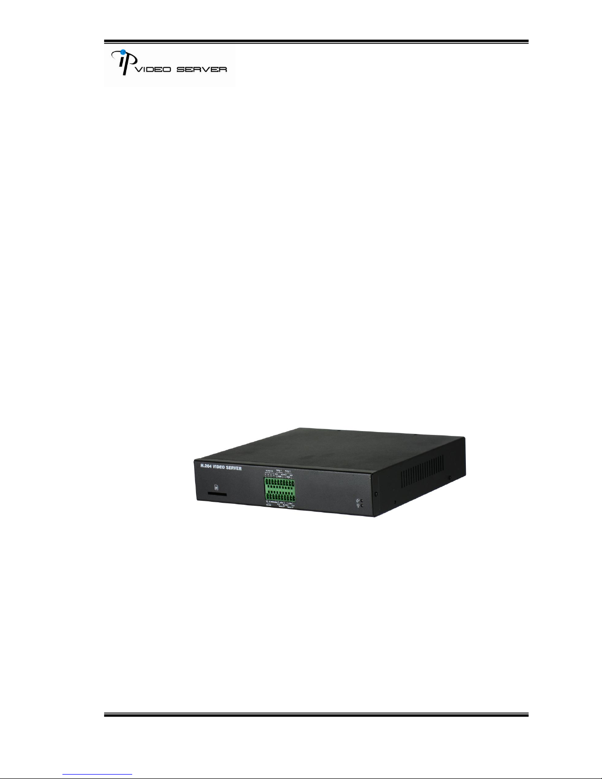
This is a four channel H.264/ MJPEG Video Server with web server built-in.
It encodes analogue signals of traditional cameras to digital signals; the users
can monitor real-time video via IE browser. H.264 and MJPEG compression
format support smooth video quality. Also, it supports SD Card backup. 2-way
audio enables the user to have a video conference. In addition, the user can
control Video Server with user friendly interface via IE browser to build a home
surveillance system.
II. Product Specifications
FEATURES:
H.264/ MJPEG compression formats
RS-485 Control Interface (PTZ)
RS-232 Interface
SD Card backup.
Wireless network connection (802.11 b/ g) - Optional
2-way audio.
4 video input
4 alarm input
4 relay out
5/34
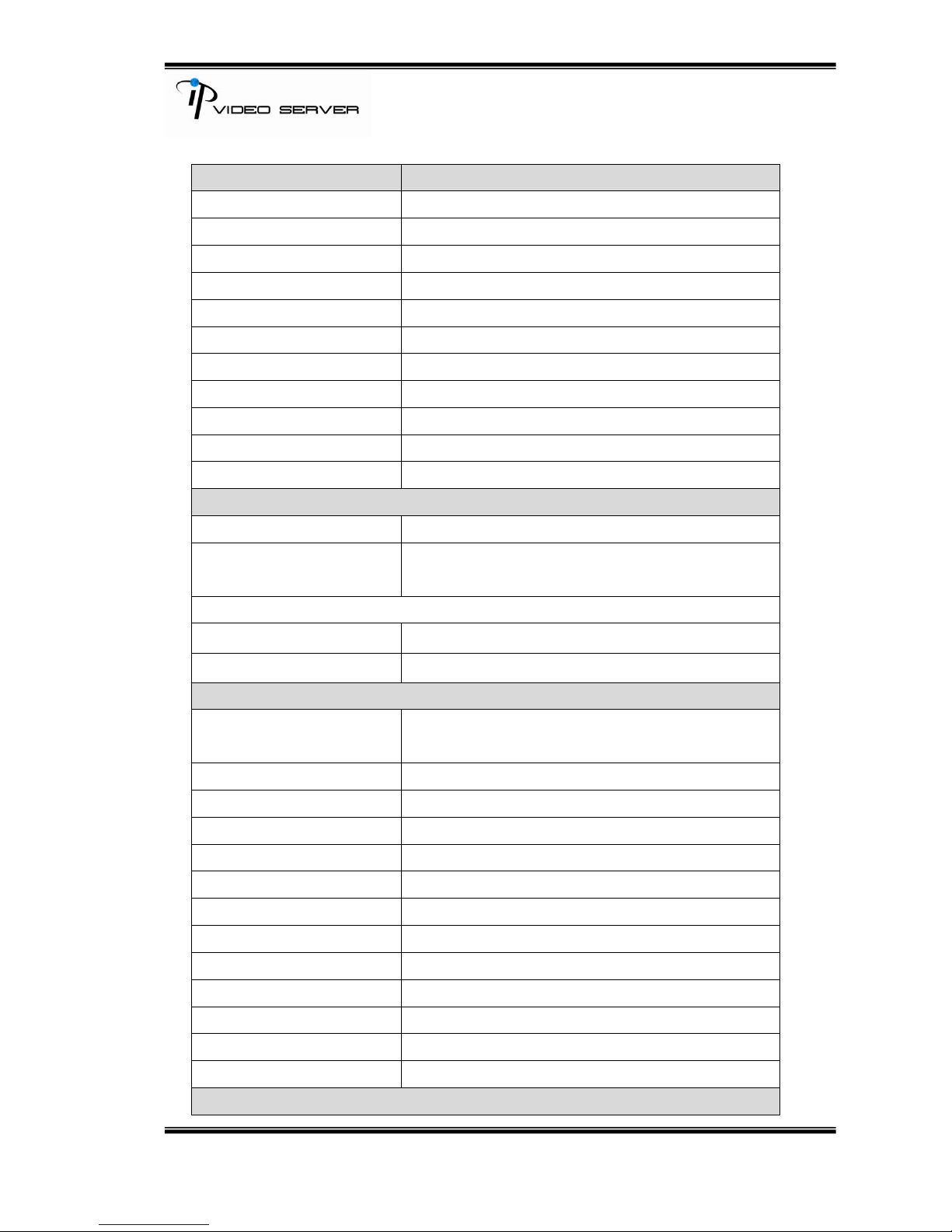
Hardware
4CH Server
CPU
ARM 9 ,32 bit RISC
RAM
256MB
ROM
16MB
Video Input
BNC x 4
Input Video Looping
BNC x 4
Audio In/Out
4 in / 1 out (RCA type)
Alarm Input
4
Relay Out
4
RS-485
X1, for PTZ control
Power
DC 12V Power Consumption :7.56W
Dimensions (WxHxD)
218x44x202mm
Network
Ethernet
10/ 100 Base-T
Network Protocol
HTTP, TCP/ IP, UDP, SMTP, FTP, PPPoE, DHCP,
DDNS, NTP
Wireless(optional)
Wireless Type
802.11b/g
Security
WEP,WPA-PSK,WPA2-PSK
System
Video Resolution
NTSC: 720x480 , 704x480, 352x240, 176x144
PAL: 720x576 , 704x576, 352x288, 176x144
Video adjust
Brightness, Contrast, Saturation, Hue
Image snapshot
Yes
Full screen monitoring
Yes
Compression format
H.264/MJPEG
Video bitrate adjust
CBR, VBR
Motion Detection
3 Areas per channel
Triggered action
Mail, FTP, Save to SD storage, Relay, Samba
Pre/Post alarm
Yes
Security
Password protection
Firmware upgrade
HTTP mode, can be upgraded remotely
Simultaneous connection
Up to 10
Audio
Yes, 2-way (Duplex Support)
SD Card Management
6/34
Recording trigger
Motion Detection, IP check, Network break down
(wire only), Relay
Video format
AVI, JPEG
Video Playback
Yes
Delete files
Yes
Browser requirement
OS
Windows7, 2000, XP, 2003, IE 6.0 or above
Hardware
Recommendation
Intel Dual Core 1.66G,RAM: 1024MB, Graphic
card: 128MB
Minimum
Intel 2.8G, RAM: 256MB, Graphic Card: 32MB
III. Product Installation
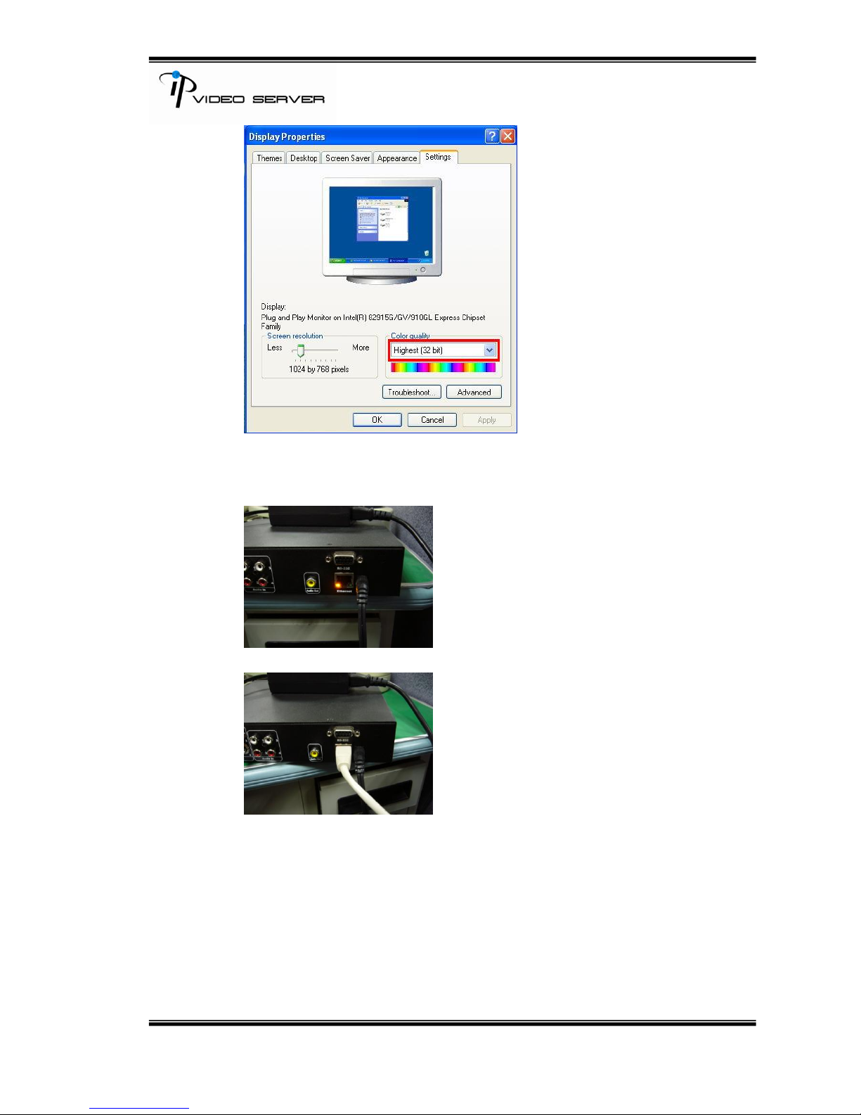
A. Monitor Setting
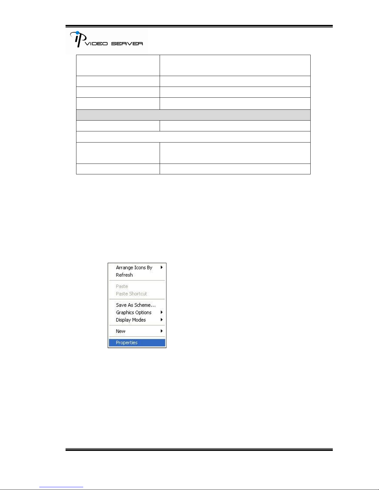
i. Right-Click on the desktop. Select “ Properties”.
ii. Change color quality to highest (32bit).
7/34
B. Hardware Installation
i. Connect power adaptor
ii. Connect Ethernet cable to Video Server
iii. Connect Video Server to a computer or Local network.
8/34
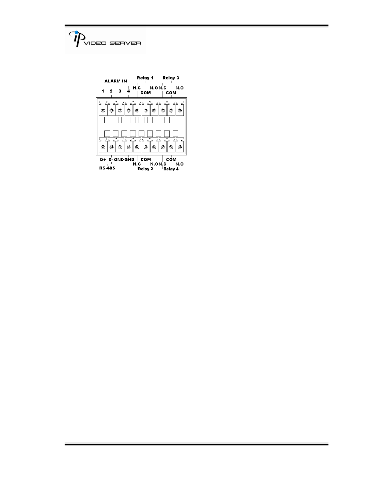
B-1 I/O Control Instruction
I/O terminal connector – used in application, for e.g., motion detection, event
triggering, alarm notifications. It provides the interface to:
1 Digital Input (GND+Alarm) – An alarm input for connecting devices that can toggle
between an open and closed circuit, for example: PIRs, door/window contacts, glass
break detectors, etc. When a signal is received the state changes and the input becomes
active.
1 Relay output (COM +N.O. / COM + N.C.) – An output to Relay switch, for example:
LEDs, Sirens, etc
Digital Input
Alarm Input
1. GND (Ground) : Initial state is LOW
2. Alarm : Max. 50mA, DC 3.3V
Relay Output
1. COM: (Common)
2. N.O. (Normally Open) / N.C. (Normally Close): Max. 1A, 24VDC or 0.5A,
125VAC
9/34
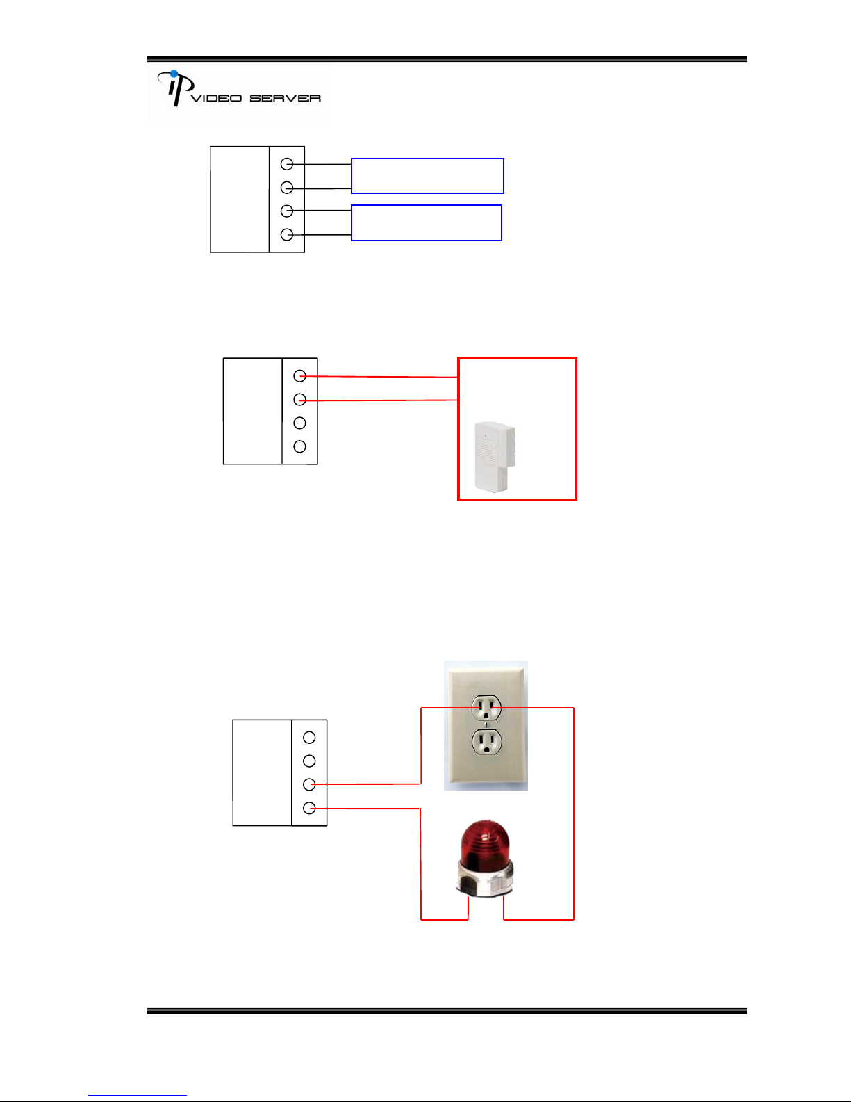
B-2. Relay Connection:
Digital Input connection
Relay Output Connection
GND
ALARM
COM
N.O./ N.C.
GND
ALARM
COM
N.O./ N.C.
Door/Window
Contacts
GND
ALARM
COM
N.O./N.C.
ALARM IN (1~4)
RELAY OUT (1~4)
10/34
C. IP Assignment
i. Use “IP Installer”, comes with CD, to assign the IP address of VIDEO
SERVER.
ii. There are two languages for IP Installer:
a. IPInstallerCht.exe: Chinese version
b. IPInstallerEng.exe: English version
iii. 3 different IP configurations based on different environments.
a. Fixed IP (Public IP or Virtual IP)
b. DHCP (Dynamic IP)
c. Dial-up (PPPoE)
iv. Execute IP Installer
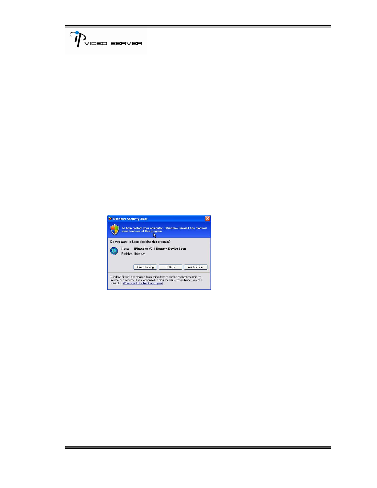
v. Use Windows XP SP2 or newer version. If the following message popup,
please click “Unblock.”
vi. The GUI of IP Installer:
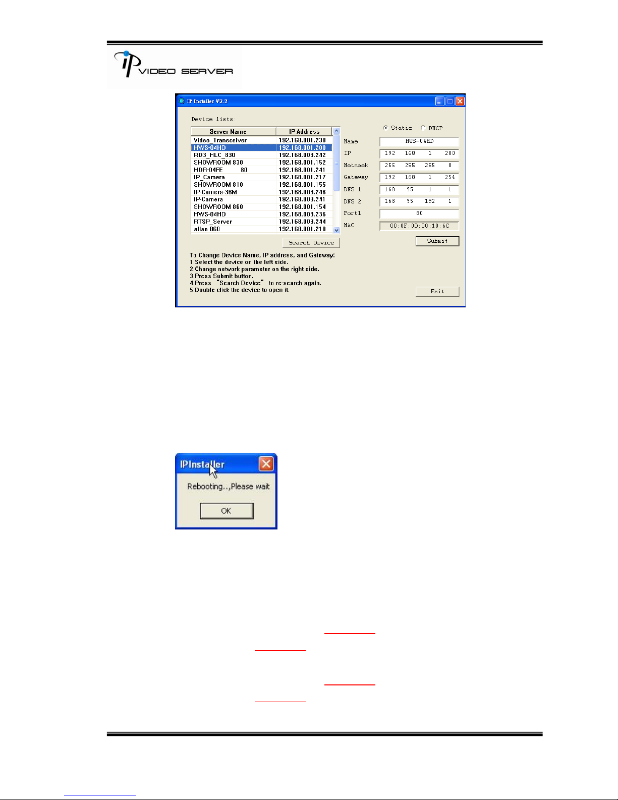
11/34
vii. IP Installer searches all IP deceives which connect with the internet and
it lists all of them on the left side or the user can click “Search Device” to
search again.
viii. When the user clicks on each IP device listed on the left side of IP
Installer, the network configuration of the IP device will show on the right
side. The user can change the parameter and click on “Submit”. And,
then, the following message will popup. Click on “OK” to reboot VIDEO
SERVER.
ix. Please make sure the subnet of PC IP address and VIDEO SERVER IP
address are the same.
The same Subnet:
VIDEO SERVER IP address: 192.168.1.210
PC IP address: 192.168.1.100
Different Subnets:
VIDEO SERVER IP address: 192.168.2.210
PC IP address: 192.168.1.100
 Loading...