

Videosec SNC-3302, SNC-4302, SNC-6032, SNC-6312IRH, SNC-5312IR User Manual

00P3NX063ZXSEA4
Full HD Multiple Streams Box IP Camera
User’s Manual
User Name: Admin
Password:
1234
Ver1.4

1
Table of Contents
1. Overview.................................................................................................................................. 2
1.1 Features........................................................................................................................2
1.2 Package Contents......................................................................................................... 3
1.3 Dimensions.................................................................................................................... 3
1.4 Connectors.................................................................................................................... 4
2. Camera Cabling....................................................................................................................... 5
2.1 Connect Power..............................................................................................................5
2.2 Connect Ethernet Cable................................................................................................ 5
2.3 Lens Mounting...............................................................................................................6
2.4 Connect Alarm I/O.........................................................................................................6
2.5 Connect RS485 (for DC12V/AC24V/PoE Model)..........................................................6
3. System Requirements............................................................................................................ 7
4. Access Camera....................................................................................................................... 8
5. Setup Video Resolution........................................................................................................ 11
6. Configuration File Export/ Import........................................................................................ 24
Appendix A: Technical Specifications........................................................................................25
Appendix B: Delete the Existing DC Viewer............................................................................... 29
Appendix C: Setup Internet Security .......................................................................................... 30
Appendix D: Back Focus Adjustment......................................................................................... 31
Log to NUUO as "Santec" :
SNC-3302 or SNC-4302 or SNC-5312IR or SNC-6032 or SNC-6312IRH

2
1. Overview
Supported with both H.264 and MJPEG standard, the product series not only
features in superior Full HD resolution for real-time streaming at 25/30 fps, but
also supplies D1 720p real-time streaming. With more computing power, the IP
Camera could provide more flexibility for users and system managers.
1.1 Features
z Progressive Scan CMOS Sensor
z Dual Streams, Full HD real-time + D1 real-time
z H.264 and MJPEG Compression
z Motion Detection
z Privacy Masks
z WDR
z Smart Picture Quality/3DNR
z Day/Night (ICR) (optional)
z Auto Iris Lens support (optional)
z Micro SD support (optional)
z BNC Analog output
z PoE support
z ONVIF Support
3
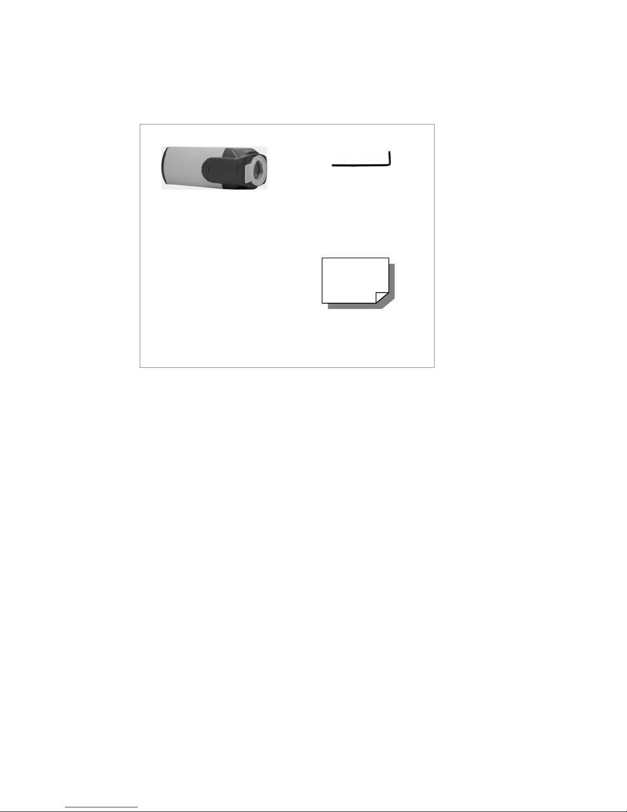
1.2 Package Contents
Please check the package contains the following items listed below.
Full HD Multiple Streams
IP Camera
Back focus adjuster
CD
(bundled software and
documentation)
Quick Guide
1.3 Dimensions
The IP Camera’s dimensions are shown below.

4
1.4 Connectors
The diagram below shows the IP Camera’s reset button and various connectors.
Definition for each connector will be given as follows.
DC 12V/ PoE
DC 12V/ AC 24V/ PoE
C/CS Mount Lens Motorized Lens
No. Definition Remarks
1 LINE OUT & LINE IN / MIC IN Two-way audio transmission
2 Power LED Power connection indication (green light)
3 Reset button Reset to factory default
4 AUTO IRIS connector Auto iris lens connector
5 NETWORK (with PoE) RJ-45 connector
6 Network LEDs Network connection and activity indication
1 Output+ 5 GND
2 Output- 6 D3 Input+ 7 D+
7 Alarm I/O
4 Input-
8 VIDEO (BNC connector) For video output
9 Micro SD Card slot For video recording storage
+
AC 24V: Power-1 DC 12V: Power
AC 24V: Earth GND DC 12V: Reserved
10
AC 24V/DC 12V connector
(AC 24V Model)
-
AC 24V: Power-2 DC 12V: GND

5
2. Camera Cabling
Please follow the instructions below to complete IP Camera installation.
2.1 Connect Power
Please refer to Section: Connectors. Alternatively, connect the Ethernet cable to
the camera’s PoE port and plug the other end of the cable into a PoE switch.
NOTE: If using PoE, make sure Power Sourcing Equipment (PSE) is in
use in the network.
2.2 Connect Ethernet Cable
Use of Category 5 Ethernet cable is recommended for network connection; to
have best transmission quality, cable length shall not exceed 100 meters.
Connect one end of the Ethernet cable to the RJ-45 connector of the IP Camera,
and the other end of the cable to the network switch or PC.
NOTE: In some cases, you may need use an Ethernet crossover cable
when connecting the IP Camera directly to the PC.
Check the status of the link indicator and activity indicator LEDs; if the LEDs are
unlit, please check LAN connection.
Green Link Light indicates good network connection.
Orange Activity Light flashes for network activity indication.
6
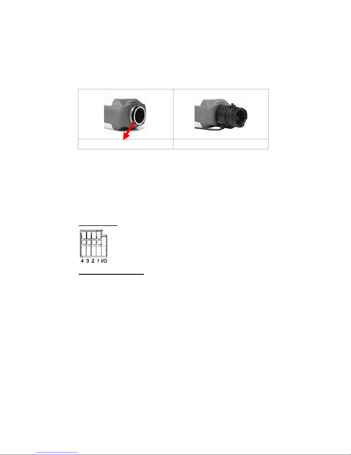
2.3 Lens Mounting
If use C-Mount lens, after removing the camera’s plastic cover, users need to
mount the C/CS mount adapter to the camera. Then attach the lens onto the
C/CS mount adapter, as the illustrations shown below.
C/CS Mount Adapter Completion
2.4 Connect Alarm I/O
The camera equips one alarm input and one relay output for alarm application.
Refer to alarm pin definition below to connect alarm devices to the IP Camera if
needed.
DC 12V/ PoE
DC 12V/ AC 24V/ PoE
PIN 1: Output+
PIN 2: OutputPIN 3: Input+
PIN 4: Input-
2.5 Connect RS485 (for DC12V/AC24V/PoE Model)
The RS-485 connector is the interface for connecting with the pan & tilt
positioning system.
PIN 6: DPIN 7: D+

7
3. System Requirements
To perform the IP Camera via web browser, please ensure your PC is in good
network connection, and meet system requirements as described below.
Items System Requirement
Personal Computer
1. Intel® Pentium® M, 2.16 GHz or Intel® Core
TM
2 Duo, 2.0
GHz
2. 2 GB RAM or more
Operating System
Windows VISTA/ Windows XP/ Windows 7
Web Browser
Microsoft Internet Explorer 6.0 or later
Firefox
Chrome
Safari
Network Card
10Base-T (10 Mbps) or 100Base-TX (100 Mbps) operation
Viewer
ActiveX control plug-in for Microsoft IE

8
4. Access Camera
For initial access to the IP Camera, users can search the camera through the
installer program: DeviceSearch.exe, which can be found in “DeviceSearch”
folder in the supplied CD.
Device Search Software Setup
Step 1: Double click on the program Device Search.exe. After its window
appears, click on the <Device Search> button on the top side.
Step 2: The security alert window will pop up. Click on <Unblock> to continue.
Device Search
Step 3: Click on <Device Search> again, and all the finding IP devices will be
listed in the page. The IP Camera’s default IP address is:
192.168.0.250.
Step 4: Double click or right click and select <Browse> to access the camera
directly via web browser.
Step 5: Then the prompt window of request for entering default username
and password will appear for logging in to the IP Camera.
The default login ID and password for the Administrator are:
Login ID Password
Admin 1234
NOTE: ID and password are case sensitive.
NOTE: It is strongly advised that administrator’s password be
altered for the security concerns. Refer to Full HD Multiple
Streams IP Camera Menu Tree for further details.

9
Additionally, users can change the IP Camera’s network property, either DHCP
or Static IP, directly in the device finding list. Refer to the following section for
changing the IP Camera’s network property.
Example of Changing IP Camera’s Network Property
Users can directly change an IP Camera’s network property, ex. from static IP to
DHCP, in the finding device list. The way to change the IP Camera’s network
property is specified below:
Step 1: In the finding device list, click on the IP Camera that you would like to
change its network property. On the selected item, right click and
select “Network Setup.” Meanwhile, record the IP Camera’s MAC
address, for future identification.
Step 2: The “Network Setup” page will come out. Select “DHCP,” and press
“Apply” button down the page.
Step 3: Click on <OK> on the Note of setting change. Wait for one minute to
re-search the IP Camera.
Step 4: Click on the <Device Search> button to search all the devices. Then
select the IP Camera with the correct MAC address. Double click on
the IP Camera, and the login window will come out.
Step 5: Enter User name and Password to access the IP Camera.
Installing DC Viewer Software Online
For the initial access to the IP Camera, a client program, DC Viewer, will be
automatically installed to your PC when connecting to the IP Camera.
If the Web browser doesn’t allow DC Viewer installation, please check the
Internet security settings or ActiveX controls and plug-ins settings (refer to
Section: Setup Internet Security
) to continue the process.
The Information Bar (just below the URL bar) may come out and ask for
permission to install the ActiveX Control for displaying video in browser. Right
click on the Information Bar and select <Install ActiveX Control…> to allow the
installation.
 Loading...