

Page 1

Analog Camera User’s Manual
CD-960H
Important Safeguards and Warnings
1.Electrical safety
All installation and operation here should conform to your local electrical safety codes.
The power shall conform to the requirement in the SELV (Safety Extra Low Voltage) and the Limited
power source is rated 12V DC or 24V AC in the IEC60950-1.
We assume no liability or responsibility for all the fires or electrical shock caused by improper handling
or installation.
2.Transportation security
Heavy stress, violent vibration or water splash are not allowed during transportation, storage and
installation.
Page 2

3.Installation
Do not apply power to the camera before completing installation.
Please install the proper power cut-off device during the installation connection.
Always follow the instruction guide the manufacturer recommended.
If this product is installed in the ceiling, please make sure the installation position can sustain the min
50N.
4.Qualified engineers needed
All the examination and repair work should be done by the qualified service engineers.
We are not liable for any problems caused by unauthorized modifications or attempted repair.
5.Environment
This series analog camera should be installed in a cool, dry place away from direct sunlight or strong
light, inflammable, explosive substances and etc.
The working temperature ranges from -10℃ to +60℃. Please keep it away from the electromagnetic
radiation object and environment.
Please make sure the CCD component is out of the radiation of the laser beam device. Otherwise it
may result in CCD optical component damage.
Please keep the sound ventilation.
Do not allow the water and other liquid falling into the camera.
6. Accessories
Be sure to use all the accessories recommended by manufacturer.
Before installation, please open the package and check all the components are included.
Contact your local retailer ASAP if something is broken in your package.
7. Daily Maintenance
Please shut down the device and then unplug the power cable before you begin daily maintenance
work.
Do not touch the CCD optic component. You can use the blower to clean the dust on the lens surface.
Always use the dry soft cloth to clean the device. If there is too much dust, please use the water to
dilute the mild detergent first and then use it to clean the device. Finally use the dry cloth to clean the
device.
Please put the dustproof cap to protec t the CCD component when you do not use the camera.
Page 3

1 General Introduction
This series analog camera adopts the high sensitivity CCD and advanced circui t desi gn. I t is
featuring the high quality video, the lowest distortion, low noise and etc. This series product is
suitable to be used in surveillance system and video process system.
1.1 Features
z High-performance SONY CCD, high resolution, 700 TVL, vivid and impressive video
z Support ICR (IR Cut Removal) auto switch, auto day/nigh mode switch or external activation
to realize the surveillance both in the daytime and at night. (Note: For F481EP, F581EP,
and F781EP series product only.)
z Support WDR 500X, suitable for backlight environments.
z Support ATW (auto trace white balance),
LOCK and etc. Restore high definition and more reliable video
z Support privacy mask function. Set zone color, transparent, mosaic and etc.
z Support motion detect function. Set zone sensitivity and block display.
z Support video mirror, hue and color gain setup.
z Support backlight compensation, high light compensati on, close and etc according to the
actual environments.
z Support ATR, ATR-EX functions.
z Support 2D and 3D de-noise. High signal to noise ratio (SNR), clear and impre ssive video.
(Note: The F480EP, F480CP series product does not support 3D de-noise function.)
z Support auto electronic gain control, self-adaptive brightness.
z Support auto aperture function (DC or video drive)
z Support flange-back adjustment, suitable for multiple models from various brands
z Auto exposure function
z Support OSD (on-screen display), suitable for user self-defined setup .
z Support RS485 remote control.
z Support various languages such as English.
ANTI CR (anti-color roll), MANUAL PUSH, PUSH
1.2 Functions
Motion detect
An alarm can be generated once the re is moving object in the surveillance area. You can select
the various sensitivity levels according to your actual requirements.
Privacy mask
Support privacy mask area setup. Privacy masking area is a user-defined, four-sided area that
can not be viewed by you during the surveillance to protect the privacy information (such as the
keyboard zone of the ATM).
Day/night mode switch (Color and black/white switch)
This function allows the camera to display the colo r vide o in the day while the black and white
video at the night. It is to enhance camera sensitivity and defi niti o n.
3
Page 4

Auto gain function
To output the standard video signal in the diff er e nt il lumination environments, the amplifier needs
to adjust in a wide range. The system can enhance the camera sensitivity in low illumination and
enhance the video signal output to get the clear and high definition video.
SNR
It is the ratio value between the signal voltage and the noise voltage. The higher the SNR value,
the lower the adverse effect. It is to guarantee the clear video.
OSD
User-friendly on-screen display for you to select the different functions.
INT and LL
There are two synchronization modes: INT/LL. INT is to use the oscillator of the camera to
generate the synchronization signal to complete the scan and synchronization. The LL is to
provide the AC current to the camera to realize the scan and synchronization.
White Balance
The white balance refers to the camera to restore the white object color. It allows th e camera to
adjust the color temperature in indoor and outdoor environment, just like our human eyes does.
ICR
The IR cut removal is to filter the IR light in the daytime and then auto switch to the general fitter
at night. This function allows the camera to output the high sensitivity and clear video.
Auto exposure
System can automatically set shutter speed and iris value according to the snapshot video
exposure condition.
Low illumination
The system can output the proper video even in dark environment.
4
Page 5

BLC
Once there is strong light at the back of the object, the main object video may become dark.
Backlight compensation technology is to automatically compensate the light to get vivid video.
You can refer to the following two figures to see the result of the backlight compensation
technology function.
Before After
WDR
When there is strong light, shadow and backlight all in one surveillance environment, the camera
output video may become white owning to the extra exposure while some sections become black
owning to the insufficient exposure. All of these will adversely affect the video quality. WDR is to
balance the light between these two sections .
You can compare the follow figure with the above figure on the left.
ATR and ATR-EX
ATR (Adaptive Tone-curve Reproduction) function allows the camera to digitally calculate the
video color again and then adjust the bright n ess to enhance the video quality. This function can
effectively enhance the color and black zone of the video when there is sharp light contrast in the
environments.
5
Page 6
HLC
HLC (High Light Compensation) function can effectively remove the risk of over exposure and
guarantee the proper monitor video when there are strong lights.
De-noise (Noise reduction)
There may be too much noise when you are monitor in the low illumination environments. You
can digitally calculate to reduce the noise to get the clear video.
Digital image stabilization
When the installation position is of much vibration, you can enable this function to guarantee
clear and stable video.
Digital zoom
This function can allow you to clearly monitor the remote object. The camera can zoom in the
remote object and then output.
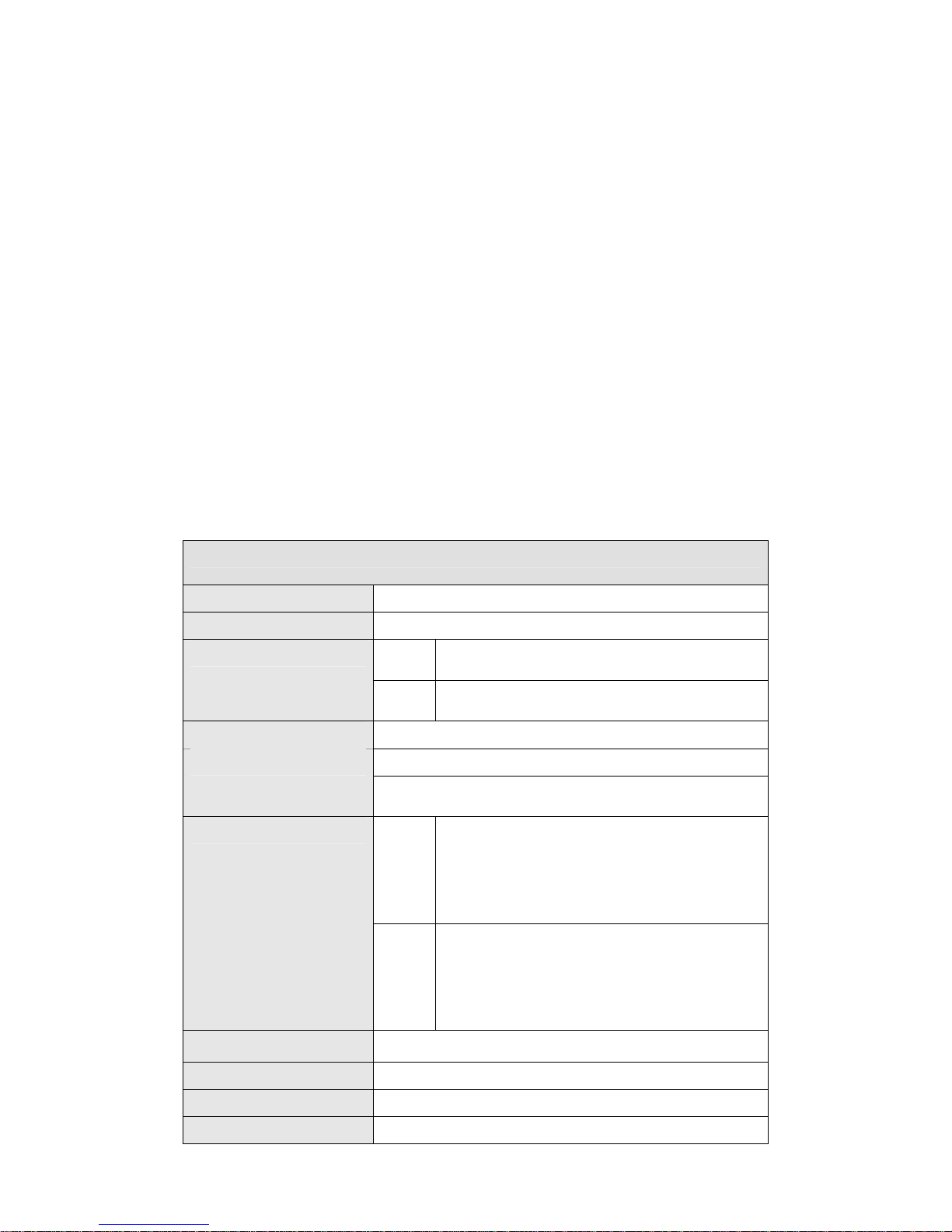
1.3 Specifications
Please refer to the following sheet for specification.
CD-960H
Video Processor
Video Format PAL/NTSC
Effective Pixel
Resolution (PAL) 960x576TVL
Min Illumination
Electronic Shutter
1/3" SONY EX view HAD CCD
PAL
NTSC
Color:0.02Lux/F1.2
Black and white:0.005Lux/F1.2
PAL Auto: 1/50s~1/100,000s
NTSC Auto: 1/60s~1/100,000s
976(H)×582(V)570K pixels
976(H)×494(V)480K pixels
Manual:
1/50s,1/120s,1/250s,1/500,1/1000s,1/2000s,
1/4000s,1/10,000s
Manual:
1/60s,1/100s,1/250s,1/500,1/1000s,1/2000s,
Iris Control Mode Auto/manual
Lens Connection Type C/CS mount
Day/Night Switch ICR auto switch
Synchronization Mode INT/LL
1/4000s,1/10,000s
6
Page 7

Video Output
SNR Above 60dB
1Vp-p Composite Output(75Ohm/BNC)
Menu
LENS Manual/Video/DC
SHUTTER/AGC Auto/Manual
BACKLIGHT
(BLC)
WHITE
BALANCE
DAY/NIGHT
MODE
PICTURE
ADJUST
ATR Off/luminance/contrast
MOTION
DETECT
PRIVACY
MASK
NR Level/Y level/C level
Camera ID Character/position
Off/BLC/HLC(High light compensation )
ATW/ ANTI CR /manual/push lock/push/user 1/user 2
Auto/external trigger/black and white/color
Mirror/brightness/contrast/sharpness/hue/gain
Detect sensitivity/block display/area selection
Area selection/color/transparent/mosaic
Language English/Japanese and etc
Communication Port RS485
Working Temperature -10ºC ~ +60ºC
Power
Power Consumption
Dimension (mm)
Weight 500g
AC24V±10% / DC12V±10%
6W Max
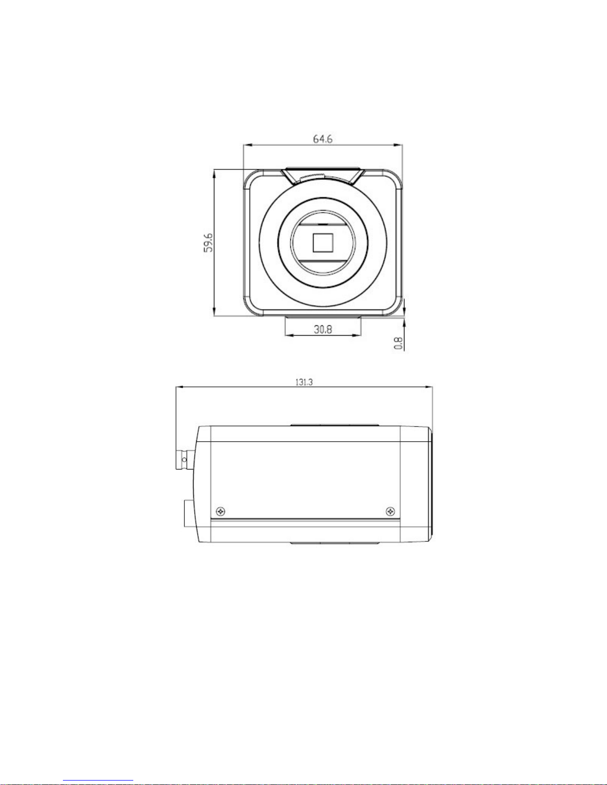
131.3(L)×64.6(W)×61.2(H)
7
Page 8
2 Framework
2.1 Dimension
Please refer to the following figures for dimension information. See Figure 2-1 and Figure 2-2.
Figure 2-1
Figure 2-2
8
Page 9
2.2 Side Panel
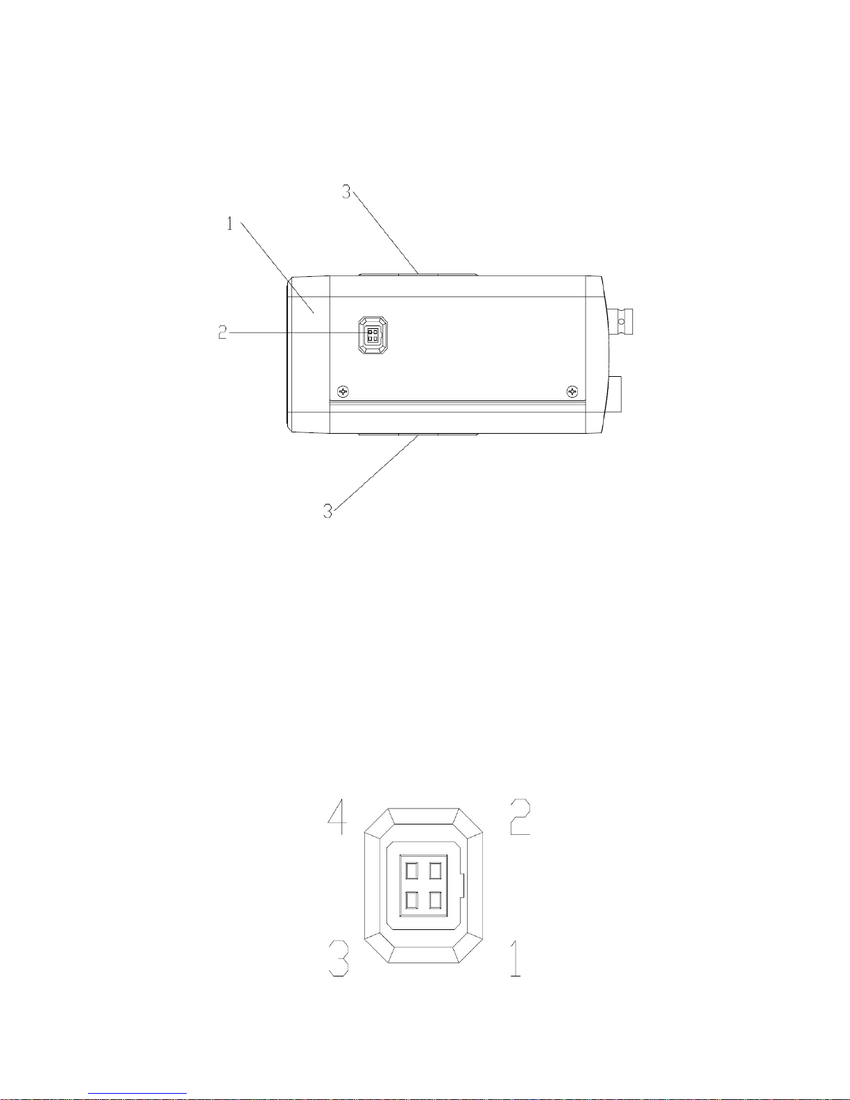
This series analog camera side panel stru ct ur e is shown as below. See Figure 2-3.
1: Flange-back. 2. Auto aperture port 3.Pedestal to secure the bracket
Figure 2-3
1 Flange-back
Usually the flange-back has been set to the proper position before it is shipped out of the factory.
But sometimes, you may still need to adjust a little bit to let it be suitable for different lens. Please
follow the steps listed below:
z Secure the lens.
z Loosen the screw to unlock the flange-back
z Turn the lens until you see the clear video.
z Fix the screw again.
2. Auto aperture port
The auto aperture port interface is shown as below. See Figure 2-4.
Figure 2-4
9
Page 10
Please refer to the following sheet for detailed information.
The video driver auto aperture uses the three pins: Power, Video and GND. The DC driver auto
aperture uses the four pins: Damp+, Damp-, driver +, Driver -.
Video DC
1 Power Damp-
2 NC Damp+
3 Video Driver+
4 GND Driver-
3. The pedestal to secure the bracket
It is to install the bracket.
Important
Please contact our local retailer if you want to use the video drive lens.
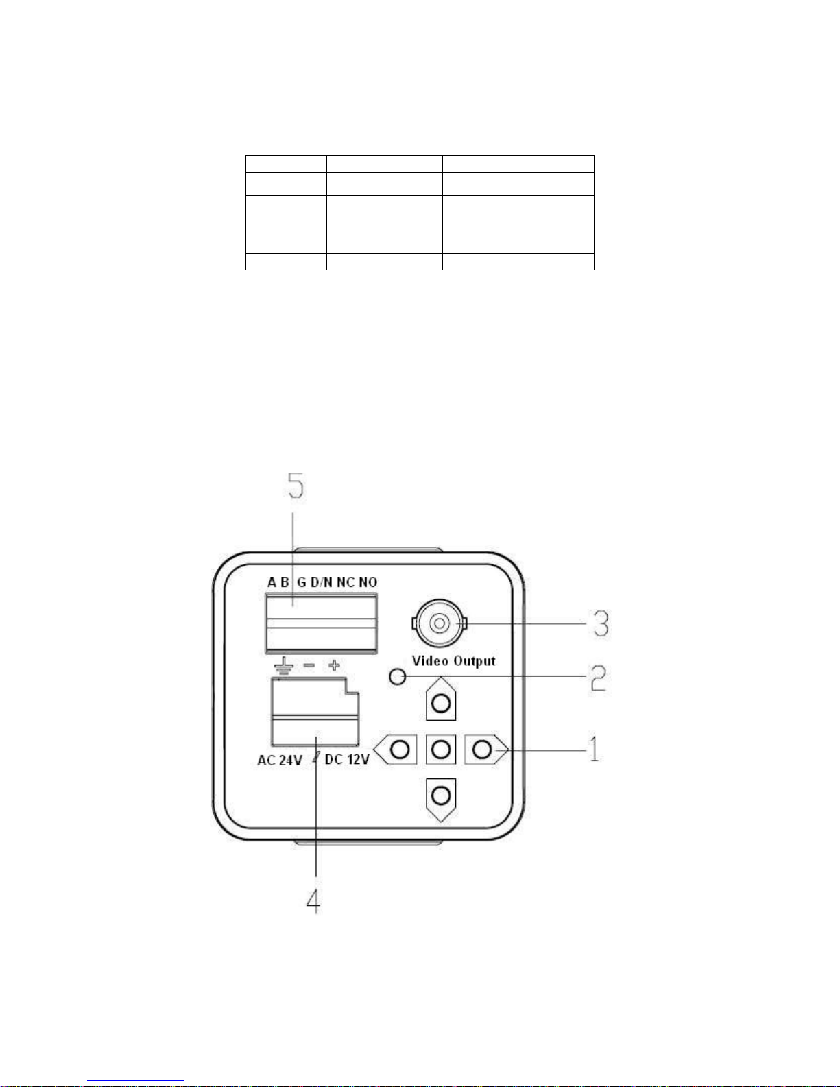
2.3 Rear Panel
2.3.1 CD-960H
This series product rear panel is shown as in Figure 2-5.
Figure 2-5
10
Page 11
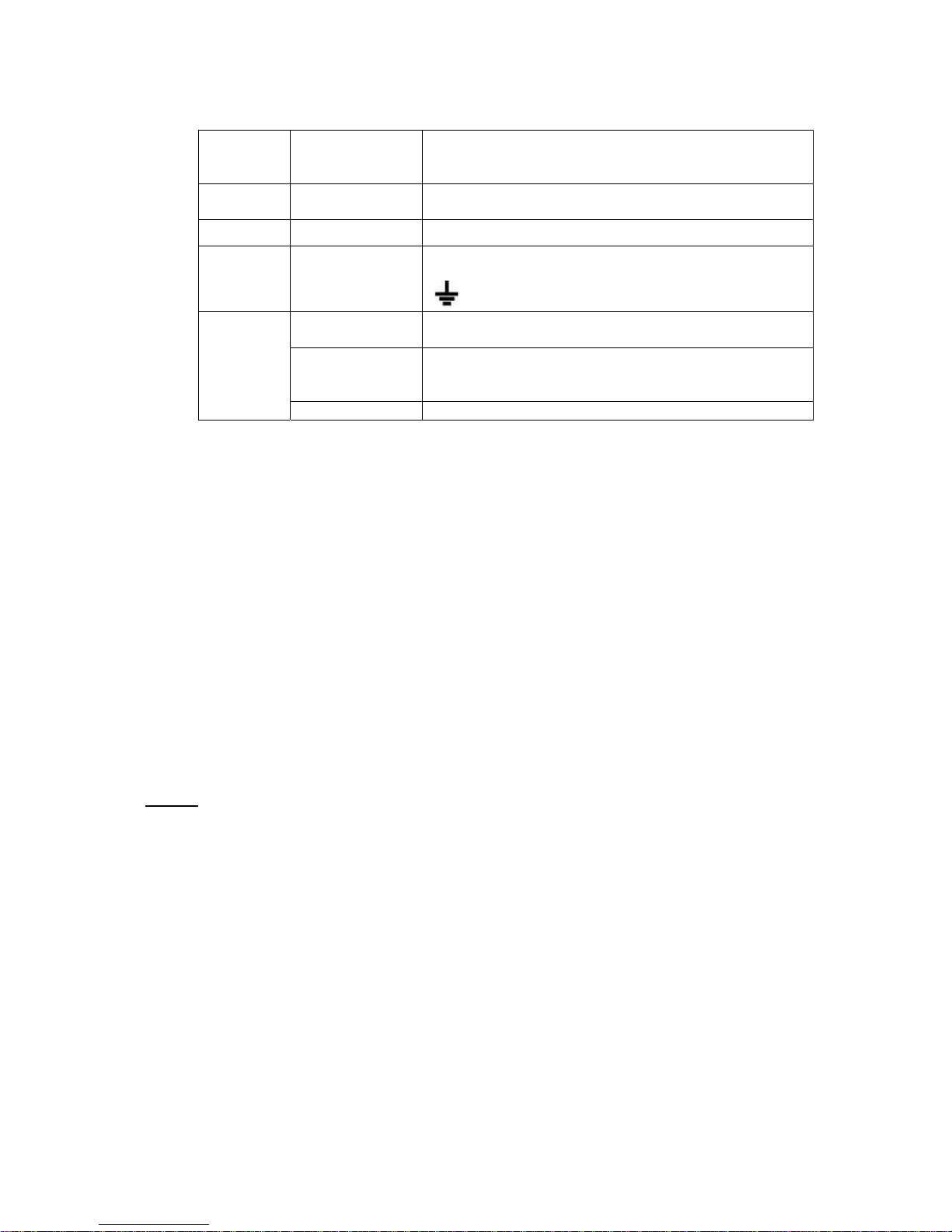
Please refer to the following sheet for detailed information.
1 Menu button Press it for two seconds to call the menu. Use the
up/down button to move the function and use the
left/right button to select the item.
2 Power indication
3 Video output It is to output analog video signal.
4 Power “+” is to connect to the positive end.
5
Important
light
A,B Support RS485 control. Can connect to the DVR,
G,D/N It is the input port for the device (such as the IR light)
NC, NO Connect to the external alarm device .
It is the power indication light. The LED light is on
when the power supply is proper.
“-” is to connect to the negative end.
” is the ground end.
“
keyboard and etc to realize remote control.
to confirm the day/night environment so that the device
can realize the day/night switch.
Please refer to the specifications sheet for power voltage and working environment
information.
Installation
Important
z Please make sure all the accessories are included.
z Please make sure the lens is the CS model and it is less than 1Kg.
z The jut after the installation section shall be less than 5mm.
z Please use the C/CS mount adapter when you are using C model lens.
2.4 Installation
This series camera support two installation modes: wall mount and in-ceiling mount.
All the steps listed below are based on the in-ceiling mount. Th e wall mo unt installation is the
same.
Step 1
Please select the corresponding installation bracket before your installation.
If it is the cement wall, please install the expansion bolt first. Please make sure the expansion
bolt installation position shall be identical with the b r acket . Then you can install the bracket. See
Figure 2-6.
If it is the wood wall, you can use the self-tapping bolt to install the bracket directly.
Important
Please make sure the installation surface can min support the 3X weight of the camera and the
bracket.
11
Page 12
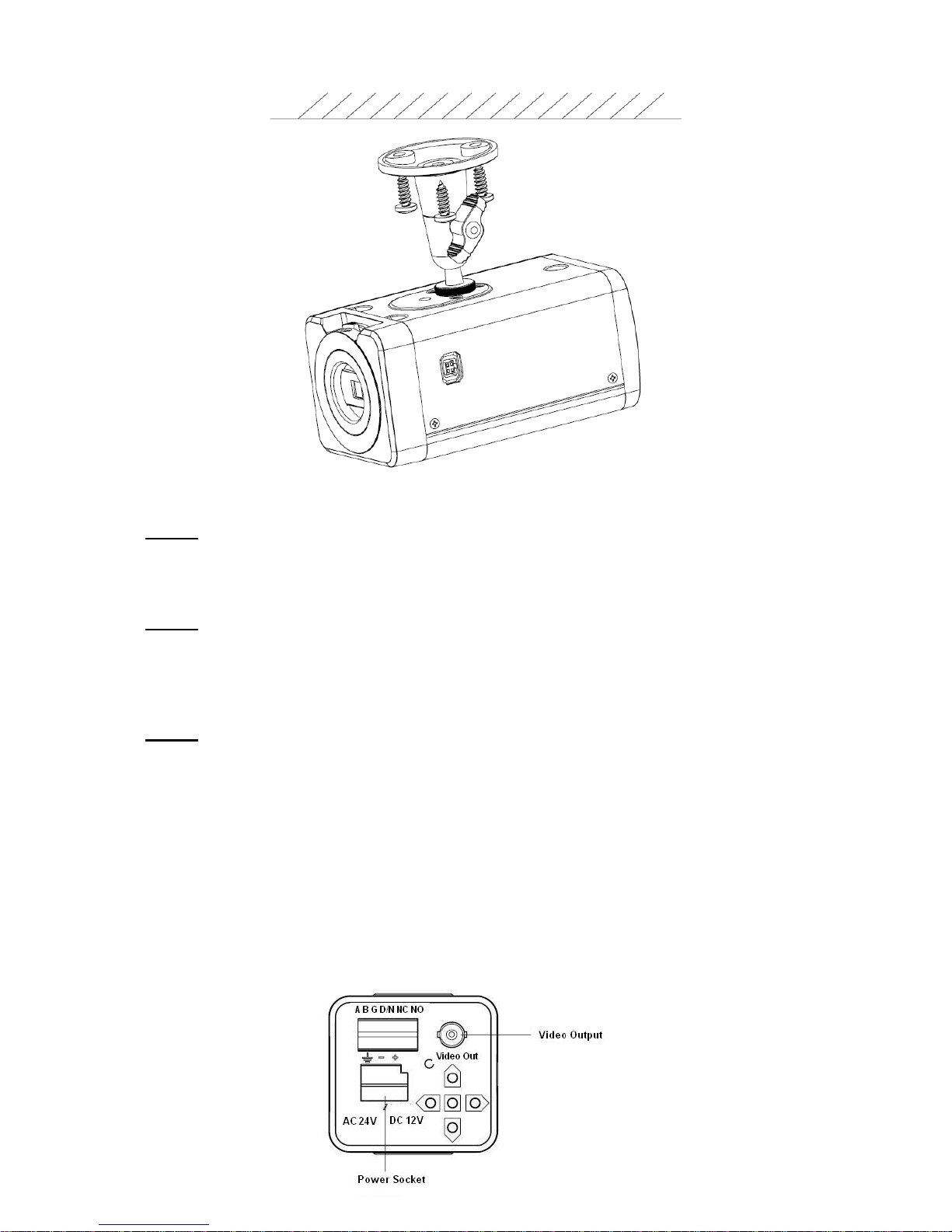
Figure 2-6
Step 2
Install the camera. Please use the installation pedestal at the top of the camera to turn the
camera into the bracket.
Step 3
After adjust the camera to proper surveillance position, secure the knob of the bracket to fix the
camera.
Step 4
Install the lens to the camera head. Adjust the focus and then secure the lens. See
2.5 Hardware Installation
Please refer to the following figure for rear panel connection. See Error! Reference source not
found..
Important
Before you boot up the camera, please make sure the provided power voltage is conform to the
camera specifications. Usually the analog camera voltage is DC 12V or AC 24V.
12
Page 13
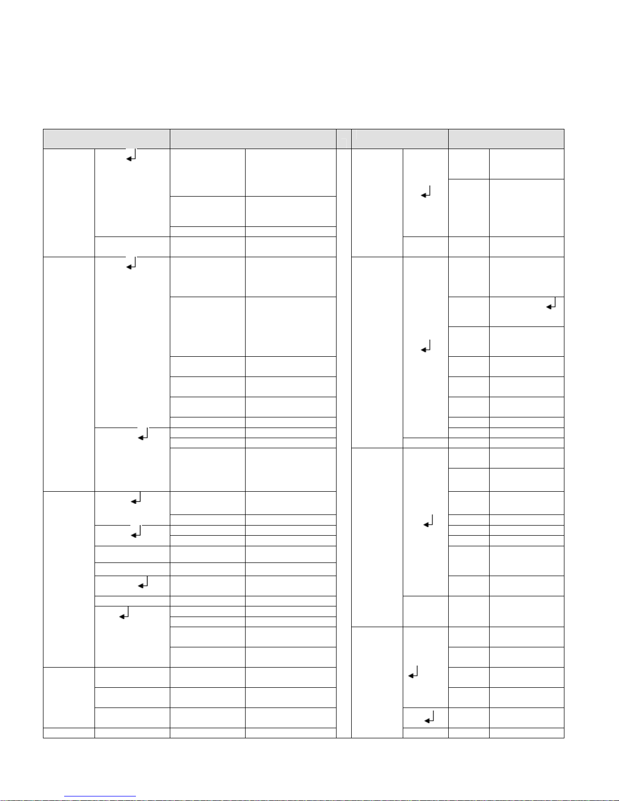
3 Menu
3.1 Main Menu
Please refer to the following sheet for menu information.
THE 1st MENU THE 2ND MENU
LENS
SHUTTER
AGC
WHITE
BALANCE
BACKLIG
HT
PICT BRIGHTNESS 0-255
AUTO
MANUAL
AUTO
MANUAL
USER1
USER2
ANTI CR
PUSH LOCK
MANUAL
PUSH
ATW
OFF DAY→
BLC
HLC
TYPE DC,VIDEO
MODE AUTO.
SPEED
HIGH
LUMINANCE
MODE SHUTTER+AUTO
BRIGHTNESS 0-255 AREA
LOW
LUMINANCE
MODE AUTO GAIN
BRIGHTNESS
MODE SHUTTER+AGC
SHUTTER 1/50~1/10, 000
AGC 6.00~44.80
B-GAIN 0-255
R-GAIN 0-255 LEFT 000~468
B-GAIN 0-255 RIGHT 000~468
R-GAIN 0-255 COLOR 1~8
LEVEL 018-040
SPEED 0-255
DELAY CNT 0-255
ATW FRAME ×0.50~×2.00
ENVIRON
MENT
ON,
OFF
DETEC
IRIS
AUTO IRIS
SHUTTER
OFF
×0.25~×1.00
INDOOR
OUTDOOR
THE 1st MENU THE 2ND MENU
ATR
MOTION
DETECT
PRIVACY
MASK
DAY/NIG
HT
ON
OFF
ON
OFF
ON
OFF
AUTO
B/W
COLOR
LUMIN
ANCE
CONTR
AST
T
SENSE
BLOCK
DISPLA
Y
MONIT
OR
AREA
SEL
TOP
BOTTO
M
LEFT 000-288
RIGHT 000-288
AREA
SEL
TOP
BOTTO
M
TRANS
PAREN
T
MOSAI
C
BURST
DELAY
CNT
NIGHT
NIGHT
→DAY
BURST
LOW
MIDDLE
HIGH
LOW
MIDLOW
MID
MIDHIGH
HIGH
000-127
ON/OFF/SET
ON
OFF
1/4-1/4
000-288
000-288
1/4~4/4
000~288
000~288
0.00~1.00
ON
OFF
ON
OFF
000-255
000-255
000-255
ON
OFF
13
Page 14
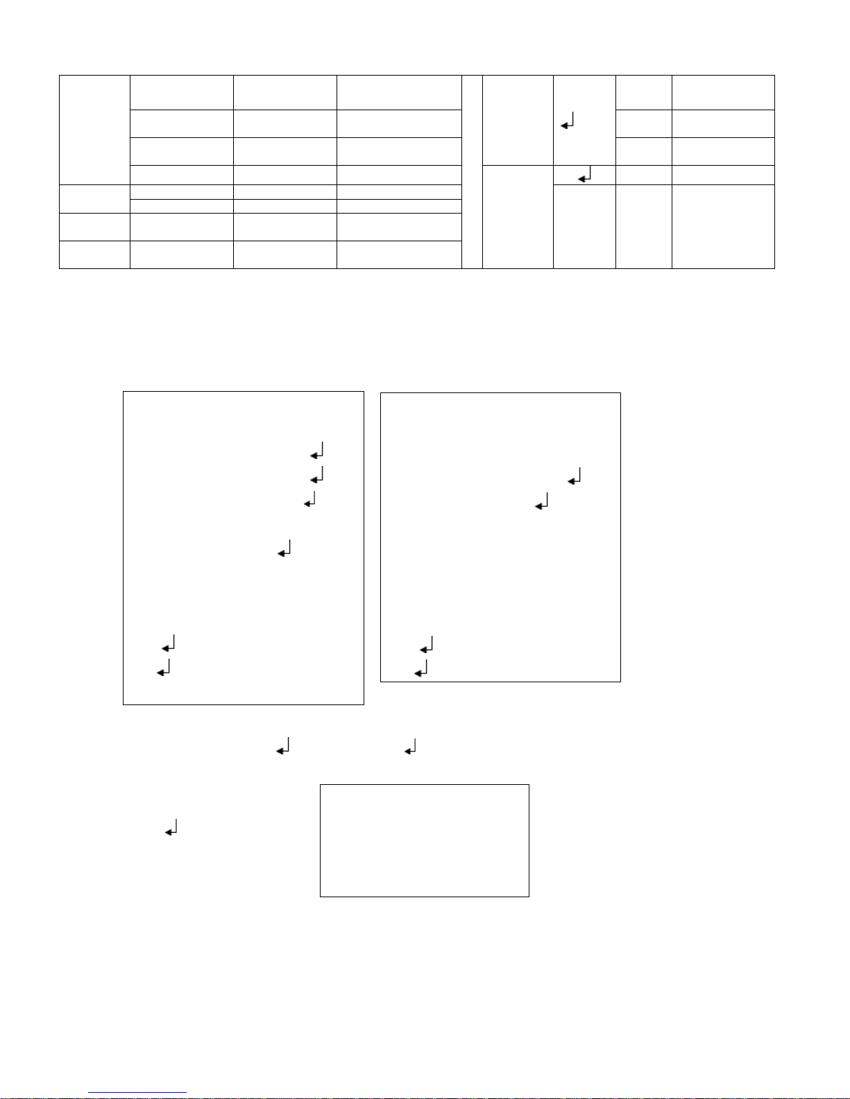
ADJUST
SYNC
LANGUA
GE
CAMERA
RESET
CONTRAST 0-255
SHARPNESS 0-255 Y
HUE 0-255
GAIN 0-255
INT
LL
ENGLISH
NR
CAMERA
ID
ON
OFF
NR
MODE
LEVEL
C
LEVEL
OFF,Y/C, Y,
C
000-015
000-015
3.2 Main Interface
Press the menu button for 2 seconds; you can see the OSD menu appear in the monitor.
3.2.1 F481EP and F480CP
MENU
LENS
SHUTTER⁄AGC
WHITE BALANCE
BACKLIGHT OFF
AUTO
AUTO
ATW
MENU
PRIVACY MASK OFF
DAY/NIGHT
NR
CAMERA ID OFF
AUTO
3.3 Detail
ed
Oper
PICT ADJUST
ATR OFF
MOTION DETECT OFF
NEXT
EXIT
SAVE ALL
corresponding parameter. You can click the confirm button to go to the sub-menu if current
parameter checked with
. Select the BACK to go back to previous menu.
3.3.1 LENS
Auto
z Mode: The parameter includes DC/VIDEO.
The DC is the DC auto iris and the VIDEO is
video drive lens.
Please connect to the auto iris port when you select the auto iris lens.
z Mode: It includes auto/on/off.
z Speed: Click the left/right button to set the value. The value ran ges from 0 to 255.
AUTO IRIS
TYPE DC
MODE AUTO
SPEED 080
RETURN
SYNC INT
LANGUAGE ENGLISH
CAMERA RESET
BACK
EXIT
SAVE ALL
Use the
up/down
button to
move the
cursor to the
ST
1
MENU, Use the left/right button to set the
ation
14
Page 15
Manual
It is the manual iris lens.
3.3.2 SHUTTER GAIN
The parameter includes: auto , manual .
AUTO
AUTO SETUP
HIGH LUMINANCE
MODE SHUTTER+AUTO IRIS
BRIGHTNESS 028
LOW LUMINANCE
MODE AGC
BRIGHTNESS ×1.00
RETURN
z High luminance/low luminance: It is the high brightness/low brightness.
z Mode: The high luminance parameter includes shutter+auto iris, auto iris, and shutter. The
low luminance parameter includes auto gain control (AGC), off.
z Brightness: The high luminance parameter ranges from 0 to 255. Please use the left/right
button to set. The low luminance parameter includes ×0.25,×0.50,×0.75,×1.00.
Manual
z Mode: Right now the system supports shutter, slow shutt er, a nd WDR shutter.
z Shutter: The parameter includes 1/50, 1/120, 1/250, 1/500, 1/1000, 1/2000, 1/4000, 1/10,000.
MANUAL SETUP
MODE SHUTTER+AGC
SHUTTER 1⁄50
AGC 6.00
RETURN
z Auto gain: The parameter includes 6.00, 12.00, 18.00, 24.00, 30.00, 36.00, 42.00, and 44.80.
3.3.3 WHITE BALANCE (WB)
The parameter includes: manual , anti cr, push lock, user1 , user2 , ATW .
Manual
MANUAL WB
LEVEL UP
LEVEL DOWN
PRESET
RETURN
15
Page 16
User1
USER1 WB
B-GAIN 030
R-GAIN 033
z B-gain: It is to adjust the blue gain. Please use the left/right button to set. The value ranges
from 0 to 255.
z R-gain: It is to adjust the red gain. Please use the left/right button to set. The value ranges
from 0 to 255.
Note:
The user2 setup is the same with the user1.
ATW
z ATW: It is the auto trace white balance. The camera can adjust the color temperature
z Speed: The value ranges from 0 to 255. Please use the left/right button to set.
z Delay control: The value ranges from 0 to 255.Please use the left/right button to set.
ATW
SPEED 239
DELAY CNT 003
ATW FRAME ×1.00
ENVIRONMENT INDOOR
RETURN
according to the actual color hue environments.
z ATW frame: The parameter includes ×0.50、×1.00、×1.50、×2.00.
z En vironment: The parameter includes: indoor, outdoor. Please use the left/right button to set.
Push lock
It is to click the OK button to lock the white balance.
Anti-color roll (ANTI CR)
Click it to enable the color roll control function.
3.3.4 HLC/BLC
The backlight compensation parameter includes: OFF, BLC, HLC.
z BLC: This function allows you to see the vivid video in the backlight environment.
z HLC: This function allows you to see the vivid video in the highlight environment.
16
Page 17

3.3.5 PICTURE ADJUST
Click the confirm button to go to the sub-menu.
PICT ADJUST
MIRROR OFF
BRIGHTNESS 000
CONTRAST 128
SHARPNESS 128
HUE 128
GAIN 128
RETURN
z Mirror: It is to set the horizontal mirror. The parameter includes on, off.
z Brightness: The value ranges from 0 to 255. Please use the left/right button to setC ontra st:
The value ranges from 0 to 255. Please use the left/right button to set. Sharpness: The value
ranges from 0 to 255. Please use the left/right button to set. Hue: The value ranges from 0 to
255. Please use the left/right button to set.
z Gain: The value ranges from 0 to 255. Please use the left/right button to set. (Note: it is the
color gain )
3.3.6 ATR/ATR-EX
The parameter includes on, off .
Select the on button and then click the confirm button to go to the sub-menu.
ATR
LUMINANCE MID
CONTRAST MID
RETURN
z Luminance: The parameter includes: low, middle, high.
z Contrast: The parameter includes: low, middle low, middle, middle high, high.
3.3.7 MOTION DETECT
The parameter includes: on/off .
Select the on button and then click the confirm button, you can go to the sub-menu.
MOTION DETECT
DETECT SENSE 111
BLOCK DISP OFF
DETECT AREA
MONITOR AREA ON
AREA SEL 1/4
TOP 000
BOTTOM 000
LEFT 000
RIGHT 000
RETURN
17
Page 18

z Detect sensitivity: The value ranges from 000 to 127. Please use the left/right button to set.
z Block: display: The parameter includes on, off, set
. Click the set button; you can use the
direction buttons to set the area to display the block.
z Monitor area: The parameter includes on, off.
z Area selection: The value ranges from 1/4 to 4/4. Please use the left/right button to set.
System max supports 4 areas. You can use the up/down/left/right button to set.
z Top: The value ranges from 000 to 288. Please use the left/right button to set. Button: The
value ranges from 000 to 288. Please use the left/right button to set. Left: The value ranges
from 000 to 288. Please use the left/right button to set. Right: The value ranges from 000 to
288. Please use the left/right button to set. (Note: This function is invalid when the digital
image stabilization (DIS) function is on.
3.3.8 PRIVACY MASK
The parameter includes on, off .
Select the on button and then click the confirm button, you can go to the sub-menu.
PRIVACY
AREA SEL 1/4
MODE ON
POSITION
COLOR RED
TRANP 0.05
MOSAIC OFF
RETURN
z Area selection: The value ranges from 1/4 to 4/4. Please use the left/right button to set.
System max supports 4 areas. You can use the up/down/left/right button to set.
z Top: The value ranges from 000 to 288. Please use the left/right button to set.
z Bottom: The value ranges from 000 to 288. Please use the left/right button to set.
z Left: The value ranges from 000 to 468. Please use the left/right button to set.
z Right: The value ranges from 000 to 468. Please use the left/right button to set.
z Color: The value ranges from 1 to 8. Please use the left/right button to set.
BLACK,RED,GREEN,BLUE,
z Transparent: The parameter includes: 0.00, 0.50, 0.75, and 1.00.
z Mosaic: The parameter includes on, off.
3.3.9 DAY/NIGHT
The function can become valid from the external activation. This function is enabled when the IR
light on if the D/N port in the rear panel can output the 5V high-level IR light. In this way, the
device realizes the day/night mode switch.
The parameter includes: auto
Auto
DAY/NIGHT MODE
BURST ON
DEALY CNT 003
DAY→NIGHT 001
NIGHT→DAY 007
RETURN
, color, black and white , and external-trigger.
18
Page 19

z Burst: The parameter includes on, off.
z Delay control: The value ranges from 000 to 255. Please use the left/right button to set.
z Day-night: It is to set the minimum parameter to switch from the day mode to the night mode.
The value ranges from 000 to 255. Please use the left/right button to set.
z Night-day: It is to set the maximum parameter to switch from the night mode to the day
mode. The value ranges from 000 to 255. Please use the left/right button to set.
Note:
In day-night mode, the smaller the value, and the hard for the camera to switch to the black and
white mode. In night-day mode, the larger the value, and the hard for the camera to switch to the
color. Here we recommend the default value. If the system switches back and forth when you are
using, please set the value in night-day mode larger and the value in the day-night mode smaller.
Black and white
z Burst: The parameter includes on, off.
B/W
BURST OFF
RETURN
External-trigger
MODE MODE1
MODE2
RETURN
Note:
z You can use this function when you are using the external IR light. The outp ut l evel is +5V or
0V when the compatible IR light is on.
z The F481EP series product only supports the high level output IR light. The IR light
becomes valid once it connected to the device. You do not need to set in the OSD.
z The F480CP and F780CP series product does not support this function.
3.3.10 NR (NOISE REDUCE/DE-NOISE)
Click the confirm button to go to the sub-menu.
Select the on button and then click the confirm button, you can go to the sub-menu.
NR
NR MODE Y/C
Y LEVEL 004
C LEVEL 004
RETURN
z NR mode: The parameter includes off, Y/C, Y, C,
z Y level: The value ranges from 000 to 015. Please use the left/right button to set.
z C level: The value ranges from 000 to 015. Please use the left/right button to set.
19
Page 20

3.3.11 DIGITAL ZOOM
MAG 000-255
PAN 000-1023
TILT 000-511
RETURN
Note
This function is null when the digital image stabilization function is on.
3.3.12 CAMERA ID
The parameter includes on, off.
Select the on button and then click the confirm button, you can go to the sub-menu. Please use
the direction buttons to select the character or the function and then click the confirm button to
select.
In the above figure, 0001 is the camera RS485 address. System default setup is 0001. You need
to set the initial character as 1 if you want to modify current setup. Then you can set the f ollowing
three characters. After you completed all the setup, you can set the initial character as 0.
Use the up/down button to move the cursor to the mark position and then click the confirm button
to set the mark position. Please use the left/right button to select the characters and then click
the confirm button to select.
CHR1: Library 1.
CHR2: Library 2.
←→↑↓: Select the character you want to modify.
CLR: Clear current character.
POS
Mark setup
After you go to the camera ID setup interface, use the direction buttons “←→↑↓” to select the
initial character of the mark code “0”. Use the direction buttons to select the CHR1 and then use
the direction buttons to select character “1”. Click the confirm button to change the initial
character “0” as “1” You can repeat the above steps to modify the following three-digit code.
Select the character and then click the ‘CLR’, click the confirm button to remove the specified
character. Please change the initial mark code “1” as “0”. Now you have completed the camera
ID mark code. Use the direction buttons to select “POS
can go to the position setup interface. Please click the direction buttons to set the camera ID
overlay position on the screen. Click the confirm button to exit.
CAMERA ID
0001
A B C D E F G H I J K L M N O P Q R S T U V
W X Y Z 0 1 2 3 4 5 6 7 8 9 —!”# $ % & ’
()_,¥:;< = >?@﹨^*. ×+⁄
CHR1 CHR2
←→↑↓ CLR POS
RETURN
: Select it to go to the camera mask position interface.
” and then click the confirm button, you
20
Page 21

3.3.13 RS485
RS485 addr: (1-255): For F481EP series product, please refer to the camera ID setup
information for the RS485 setup.
RS485 baud rate: 9600bps.
RS485 protocol: Auto-adaptive PELCOD, PELCOP, DH-SD.
Note:
This function is for F481EP, F581EP and F781EP series product only.
3.3.14 SYNC MODE
The system supports INT and LL setup.
Important
The F480CP and F780CP series product do not support the L L sy nchr onization mode.
3.3.15 LANGUAGE
The parameter includes: English, Japanese and etc. The default setup is English.
3.3.16 CAMERA RESET
Please select the reset item and then click the confirm button to restore the factory default setup.
3.3.17 OTHERS
Next: Click it to go to the sub-menu.
Back: click it to return to the previous menu.
Return: click it to exit the menu setup interface.
SAVE ALL: Click it to save current setup.
Important
After you completed the setup, please click the “SAVE ALL” button to save current setup and
then exit the menu. It is to guarantee the camera setup after the power failure.
21
Page 22

Appendix Toxic or Hazardous Materials or Elements
Component
Name
Circuit Board
Component
Device
Construction
Material
Wire and Cable
Packing
Components
Accessories ○ ○ ○ ○ ○ ○
Pb Hg Cd Cr VI PBB PBDE
○ ○ ○ ○ ○ ○
○
○
○ ○ ○ ○ ○ ○
Toxic or Hazardous Materials or Elements
○ ○ ○ ○ ○
○ ○ ○ ○ ○
O: Indicates that the concentration of the hazardous substance in all homogeneous materials in
the parts is below the relevant threshold of the SJ/T11363-2006 standard.
Note
• This manual is for reference only. Slight difference may be found in the user
interface.
• All the designs and software here are subject to change without prior written
notice.
• If there is any uncertainty or controversy, please refer to the final explanation of us.
• Please visit our website or contact your local service engineer for more
information.
22
 Loading...