

Page 1
Defender MSS Operator's Manual
Page 2

MSS
Operator's Manual, 1.00.00
Copyright Notice
This material is copyright protected. No material may be reproduced or transmitted in any form or by
any means for any purpose without expressed written consent of VideoRay LLC.
Copyright © 2019, VideoRay LLC - The Global Leader in Micro-ROV Technology
Page 3
MSS
Operator's Manual, 1.00.00
Table of Contents
Copyright
Table of Contents
About this Document
How to Get Help
Product Overview
MSS Vehicle Configurations
Quick Start Instructions
Safety First
System Components
Pre-Dive Preparations
Dive Operations
Post-Dive Operations
ROV System Specifications
ROV Modules Specifications
Power Module
Communications Module
AHRS Module
Thruster Module
Camera Module
LED Light Module
ROV Accessories Specifications
Sonar Specifications
DVL Specifications
Manipulator Specifications
ROV GPS Specifications
System Voltage Advisory
Equipment Guide
ROV Submersible
ROV Nomenclature
Submersible Frame
Buoyancy
Ballast
Power Module
Communications Module
AHRS Module
Thruster Module
Alpha Frame Thrusters
Defender Frame Thrusters
Pro 5 Frame Thrusters
Camera Module
High Definition Camera
Low Light Camera
Light Module
Alpha Frame Lights
Defender Frame Lights
Pro 5 Frame Lights
ROV Connections
Tether Strain Relief
User Control Console
Page 4

Safety Circuits
Switches and Connections
Computer
HD Monitor
Hand Controller
Tether
Tether Specifications
Connections Summary
Accessories
Included Accessories
Mission Support Accessories
Software Guide
Greensea Interface Overview
VideoRay Interface Overview
Software Management
Folder Structure
Module Configuration
Configuration Commands
Command: vr_refresh
Updating Firmware
Command: vr_enum
Command: vr_setid
Command: vr_debug_putty
Command: vr_create_virtport
Maintenance Guide
User Maintenance Policy
Module Replacement
Power Module
Communications Module
AHRS Module
Thruster Module
Camera Module
LED Light Module
MSS Operator's Manuals
Page 5
MSS
Operator's Manual, 1.00.00
About this Document
Online Manual
This Quick Start Guide is a subset of the full version of this manual, which is available on the MSS
control panel and online in the following formats:
Installed on the MSS control panel at: Home/VideoRay/documentation/mss for viewing the
HMTL locally.
http://download.videoray.com/mss for viewing the HMTL online.
http://download.videoray.com/documentation/mss/pdf/videoray_doc_mss.pdf for viewing the
PDF online.
http://download.videoray.com/documentation/mss/zip/videoray_doc_mss.exe for downloading
the HTML and PDF files.
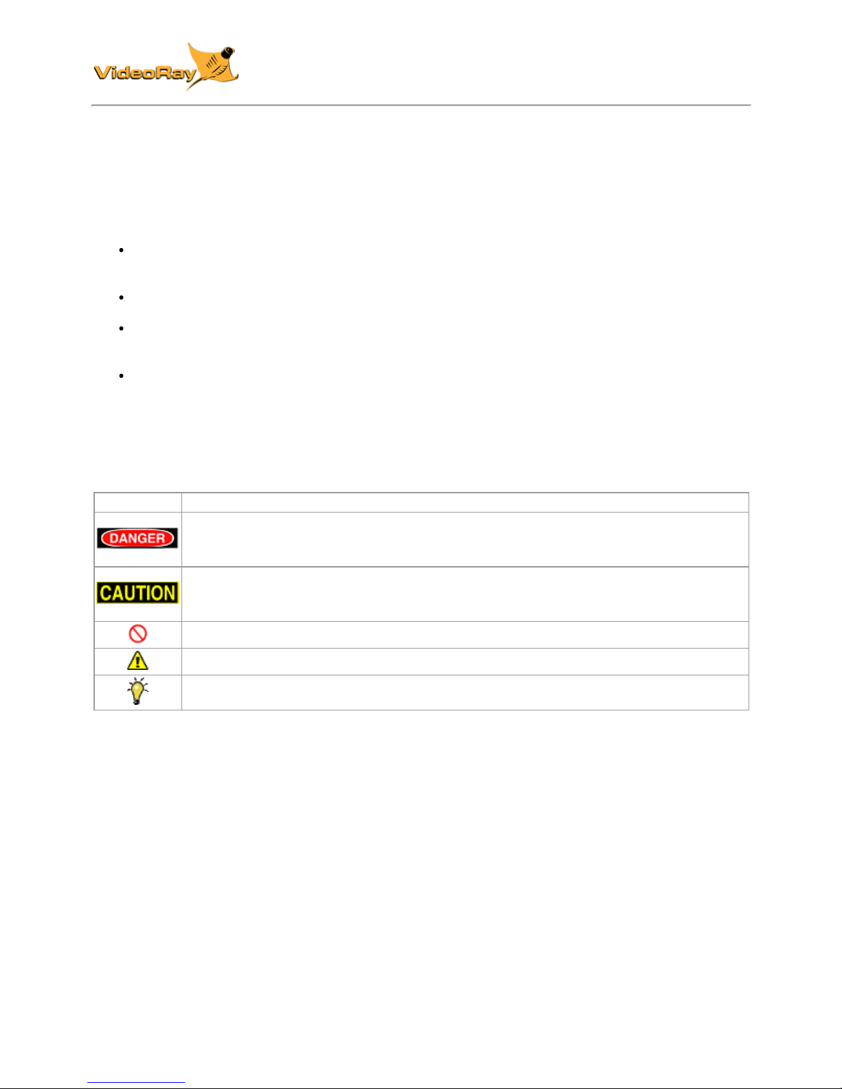
Document Conventions
Several symbols are used throughout this documentation to add emphasis and to assist in relocating
important information. The following table describes these symbols and their uses.
SYMBOL DESCRIPTION
The Danger icon is used to indicate there is a potential risk of personal injury or death.
Extra care should be taken to understand the risks, and all personnel should exercise
caution. It may also be appropriate to warn others in the immediate vicinity.
The Caution icon is used to indicate there is a potential risk of damage to the
equipment or surrounding property. Personnel should receive training in the appropriate
procedures before attempting to operate or maintain the equipment.
The Do Not icon is used to indicate that an action or activity should NOT be performed.
The Note icon is used to highlight a specific detail or point of information.
The Tip icon is used to highlight a suggestion or recommendation.
Beyond this Document
There is no substitute for experience and/or training, especially with respect to the real purpose for
which you plan to use this equipment. We encourage you to explore options beyond the scope of
these materials to expand your knowledge and skills necessary to support your applications. In
addition to this documentation, VideoRay offers training and technical support and hosts a general
user discussion forum and user image gallery.
We also realize that collectively, users of our products spend considerably more time operating our
systems than we do ourselves. Users also encounter more diverse operating environments across an
extremely broad range of applications. We highly value this vast experience base, and invite and
encourage you to share your experiences and suggestions with us. Please feel free to contact us by
any of the methods listed below.
Quality Commitment
VideoRay strives to design, manufacture, deliver and support the highest quality products and
services, including this documentation. We have made every effort to ensure that this documentation
is accurate and provides you with the most up-to-date information.
Page 6

If you find any errors in this documentation or have suggestions for improvements, each page contains
a "Help us improve this document" feedback link in the left margin (you must be connected to the
Internet to use this link).
Address
VideoRay LLC
212 East High Street
Pottstown, PA 19464
USA
Email
info@videoray.com General Information and Sales
support@videoray.com Technical Support
Telephone
+1 610-458-3000 Office
+1 610-458-3010 Fax
Disclaimer
This document is deemed accurate at the time of its writing, however it is not a legal contract and the
information contained herein should not be construed to represent any form of commitment. This
document as well as the associated products and services are subject to change without notice.
Page 7
MSS
Operator's Manual, 1.00.00
How to Get Help
Help for your MSS is available through several channels.
All Hours Self-Service / Crowd-Source Tools
Operator's Manuals and Standard Operating Procedures www.videoray.com/support/manuals.html
Software Downloads www.videoray.com/support/downloads.html
Frequently Asked Questions www.rovfaq.com
ROV User Forum www.rovinfo.com
Global Support
Email support@videoray.com
Phone +1 610-458-3000 (select option 1)
Skype videoray.support (by appointment )
Remote Sessions www.videoray.com/support/remote-support.html (by appointment )
Regional Support
VideoRay Authorized Dealers and Service Centers www.videoray.com/dealer.html
Training
Operator Training www.videoray.com/learn-more/training.html
Advanced Maintenance
Training
http://www.videoray.com/learn-more/training/advanced-maintenancetraining.html
Operational Strategies and Tactics Support
If you need help understanding how to apply your system to a specific project, contact VideoRay or
you local VideoRay dealer. We can provide guidance or help you find a certified consultant.
Page 8

MSS
Operator's Manual, 1.00.00
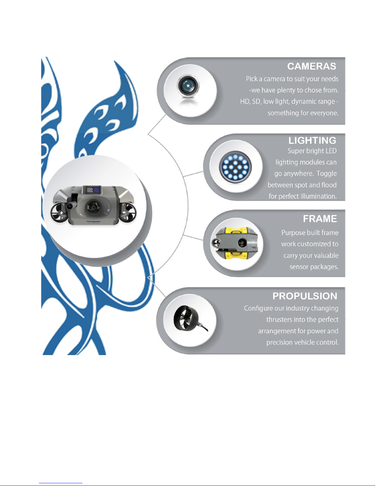
MSS Overview
The VideoRay Mission Specialist Series is the world's first ROV to deliver custom purpose-built
vehicles using a standard production packaging process. Mission Specialist ROVs are literally built
around the payload using core modules instead of figuring out how to adapt an existing vehicle
platform in order to mount the payload. The overall system represents the difference between a pickup
truck and purpose-built construction vehicles, with equal differences in performance for specific
applications.
Based on modular components and standard interfaces, the development a specific Mission Specialist
Series ROV is orders of magnitude faster than designing a vehicle form the ground up or customizing
an existing monolithic vehicle.
Modular Primary Components
Standard Interfaces
Rapid Prototyping
Additive Manufacturing
Sensor Integration
Page 9
MSS
Operator's Manual, 1.00.00
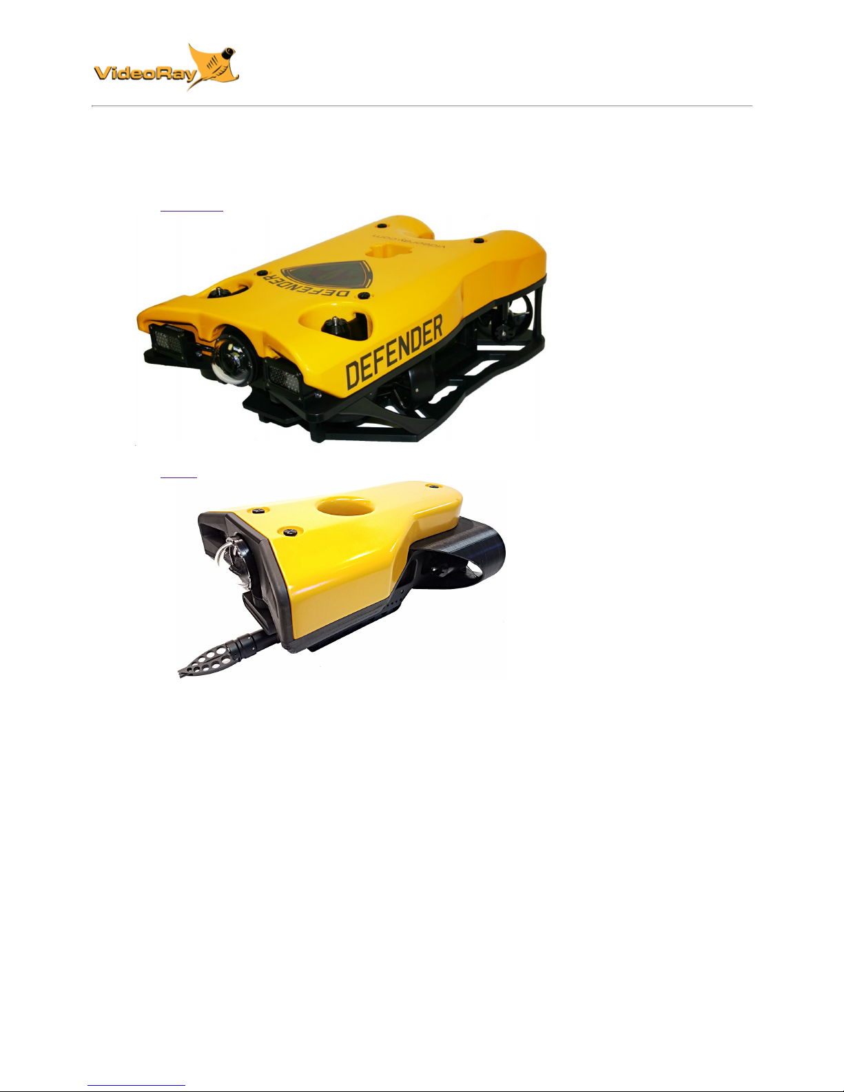
MSS Vehicle Configurations
MSS vehicle configurations include:
the Defender
the Pro 5
Vehicles are shown approximately to scale.
Page 10
MSS
Operator's Manual, 1.00.00
Quick Start Instructions
These Quick Start Instructions are streamlined to cover just the essentials of operating your MSS system.
They are provided to get you started as quickly as possible, while keeping you and the equipment safe.
They cover the equipment set up and basic operation, but are not intended to result in a comprehensive
base of knowledge or set of operational and piloting skills. The remaining sections of this documentation
should be referenced for a complete understanding of the features, capabilities, operating procedures and
maintenance requirements of your MSS system.
Topics in this Section
Safety First
System Components
Pre-Dive Preparations
Dive Operations
Post-Dive Operations
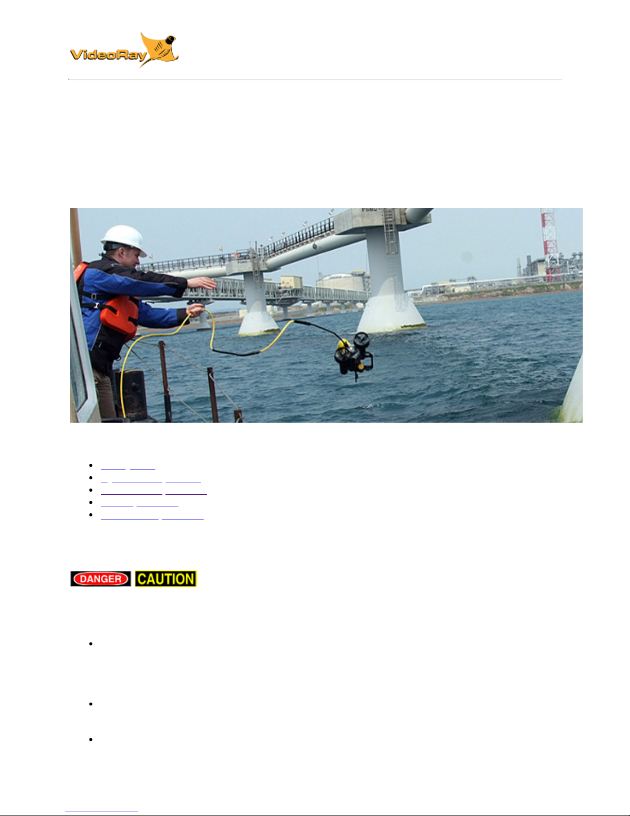
Safety First
Operating electrical devices in and near the water can be dangerous. There
is always a risk of drowning or electrocution in such an environment. Reduce these risks by using
common sense and observing safety regulations and recommended safe practices including the
following:
Never handle power cords while in contact with water or allow power cord connectors or the
control panel to enter the water. The only components that can safely be placed in water are the
submersible, any onboard accessories and tether, and only after making sure the connections
are secure.
Always test the safety components, such as GFCI switches and interlock devices, before
beginning operations. Follow the procedures described in this manual for.
Have proper safety equipment, such as PFDs (Personal Flotation Devices), on hand and make
sure you know how to use them before you need them.
Page 11
Keep fingers, hair, loose clothing and other objects away from VideoRay's propellers and other
pinch points.
Monitor weather and sea conditions and heed any warnings or alerts.
Be aware of and follow any legal ordinances or regulations in your area regarding operation of
vessels and underwater equipment in the water.
Before setting up for or commencing any dive, it is a good practice to make sure there are no
hazards to people or the equipment on land or in the water. If there are other people in the water
nearby, you should advise them that you are going to be operating the ROV. As the owner/operator, it
is your responsibility to ensure the safety of those around you as well as that of the equipment and
nearby property.
How Safe Is Safe Enough?
Addressing all aspects of safety while working in a water environment is beyond the scope of this
documentation. VideoRay encourages you to participate in safety training appropriate for your industry
and applications, including such topics as vessel operations, first aid, survival and other relevant
topics.
Introduction to the System Components
Unpack the system and familiarize yourself with the components.
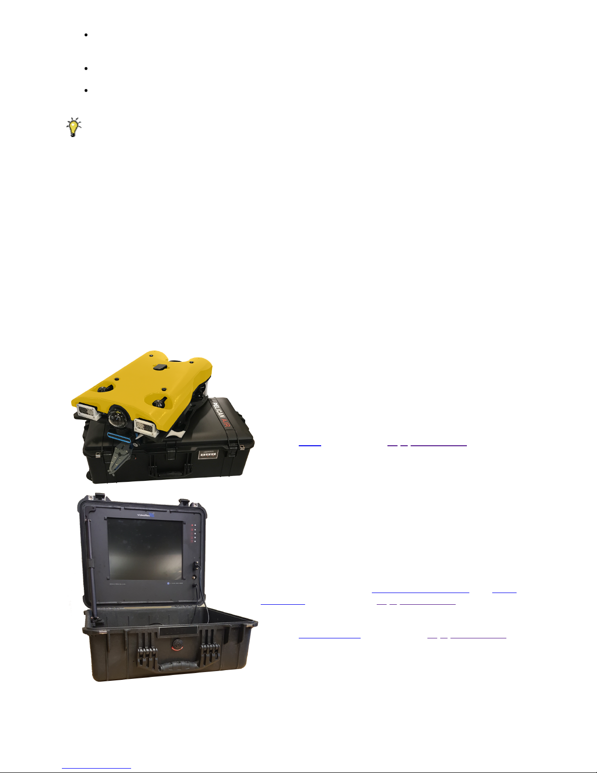
ROV
The ROV, or Remotely Operated Vehicle, carries the
cameras, lights and sensors or accessories to the
underwater places you want to observe. Thrusters provide
mobility and these systems are controlled from the surface
using the control panel and hand controller.
See the ROV section of the Equipment Guide for more
information.
User Control Console
The User Control Console includes the system's power and
communications modules, computer and hand controller,
and serves as the operator's control interface and video
display. Open the User Control Console and familiarize
yourself with the components and primary controls on the
hand controller. See the User Control Console and Hand
Controller sections of the Equipment Guide for a complete
description of all of the controls and connections.
See the Control Panel section of the Equipment Guide for
more information.
Page 12
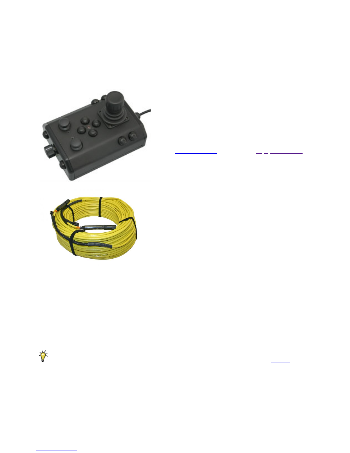
Hand Controller
The hand controller is used to pilot the VideoRay and
operate other features like the lights, camera controls and
manipulator. The hand controller is pre-programmed, but
can be customized to meet specific user or operational
needs.
See the Hand Controller section of the Equipment Guide
for more information.
Tether
The tether connects the ROV to the control panel. It
delivers power and control signals to the ROV, and returns
video and sensor data (optional) from the ROV to the
surface. Some systems come with a TDS (Tether
Deployment System), that makes the work of managing the
tether easier. The tether is also often referred to as the
umbilical.
See the Tether section of the Equipment Guide for more
information.
Additional Items
Additional items may be supplied with your system including tools, spare parts and other items. If
included, these items are described in other sections of this documentation.
Some items shown may be optional and not included with your configuration.
Pre-Dive Preparations
Select a safe and preferably level area to set up the User Control Console. See the On-site
Operations section of the Project Management Guide for more information about site selection and set
up.
The pre-dive preparations consist of five parts:
1. Visual inspection before setting up the system
2. Setting up the system including making connections
3. Power on tests of the system's safety circuits
4. Primary functions test of the systems features
5. Adjusting the ballast for the desired buoyancy (to be completed in the next phase)
Page 13
Conduct a Visual Inspection
Assuming this is your first time using the VideoRay, everything should be in proper working order and
ready to go, but it is good practice to perform a pre-dive inspection before every dive, even your first. If
any problems are noticed, they should be addressed before continuing.
1. Inspect the ROV and other system components to make sure there are no visible signs of
damage or loose or worn parts. Also check for water inside any pressure hull modules, such as
the camera.
2. Check the horizontal thrusters to make sure that the shafts are not bent and the propellers are
free to spin and are not fouled, loose or binding on the thruster guards.
3. Check the vertical thruster(s) to make sure the shaft is not bent and the propeller is not fouled or
loose or binding on the float block.
Make the Connections
It is best to start making connections at the ROV and working your way to connecting the system to
the power source.
Connecting or disconnecting cables while the system is powered on is not
recommended.
Make sure the User Control Console power switch is set to the Off position and make sure the
ROV power switch is set to the off position by pressing it.
Top View
Page 14
Side View
Some of the cables have been connected at the factory. See the appropriate sections of the
Equipment Guide for detailed information about each of the connections.
You will typically need to connect only the ROV, tether, strain relief hand controller, and power cord.
1. Connect the female end of the tether connector to the ROV. The connectors have one pin that is
offset towards the center of the connector. Make sure the connectors are clean, align the pins,
and push the connectors together - do not twist the connectors. Secure the locking collar by
screwing the halves together.
2. Connect the braided strain relief from the tether to the rear of the ROV using the retaining
screw. See the strain relief section for more information.
3. Connect the male end of the tether to the User Control Console. When not in use, keep the
tether connectors clean and protected for the best performance and reliability.
4. Connect the hand controller to one of the USB ports on the User Control Console
5. Plug the User Control Console power cord into a conventional power source (100-240 Volts AC,
50,60 Hz). Power can be supplied through a land-based power outlet, generator or battery and
inverter. See the User Control Console section of the Equipment Guide for power source
requirements.
Power On Tests
If the system does not pass any of the following tests, it should not be used
until the problem is identified and corrected.
The VideoRay MSS includes two circuit safety components.
GFCI (Ground Fault Circuit Interrupter)
LIM (Line Insulation Monitor)
Testing the Circuit Safety Components
Connect the power cord to a suitable power source.
The GFCI can be found inline in the power cord.
1. Press the GFCI Reset button to turn on the GFCI. The green LED should illuminate.
2. Press the test switch on the GFCI. The GFCI should interrupt power and the green LED should
go out.
3. Press the GFCI Reset button to restore power and continue the pre-dive steps.
Page 15
When using a power source that includes a GFCI, the VideoRay supplied GFCI is not needed and
can be removed from the power cord.
Power On and LIM Tests
Set the Power switch to the On position. The green Power On indicator light should turn on. If the
green Power On indicator light is not on, make sure the system is connected to a working power
source and the GFCI switch is turned on.
Twist the ROV Power switch to the On position. The green 400 V Power On indicator light should turn
on. If the green 400 V Power On indicator light is not on, make sure the system is connected to a
working power source and the GFCI and main power switches are turned on.
Test the LIM. The LIM can be found on the right side of the User Control Console. The GFCI switch
and the main and 400 V Power switches must both be set to On in order to perform this test.
1. The yellow Alarm light should be off. If the yellow light is on, press and hold the Reset button
until the yellow Alarm light turns off.
2. To test the LIM, press and hold the Test button until the yellow Alarm light turns on. This may
take up to 10 seconds. Release the button when the yellow Alarm light turns on.
3. Press and hold the Reset button to reset the LIM. The yellow Alarm light should turn off.
Release the button when the yellow Alarm light turns off.
Starting the VideoRay Control Software
Make sure the system is connected to a working power source and the GFCI / Circuit Breaker and
Power switches are turned on.
1. Turn on the User Control Console and wait for the system to complete the boot up process.
2. To start the MSS EOD Workspace control software, double click on the MSS icon on the
desktop.
See the Software Guide for more information about the VideoRay control software.
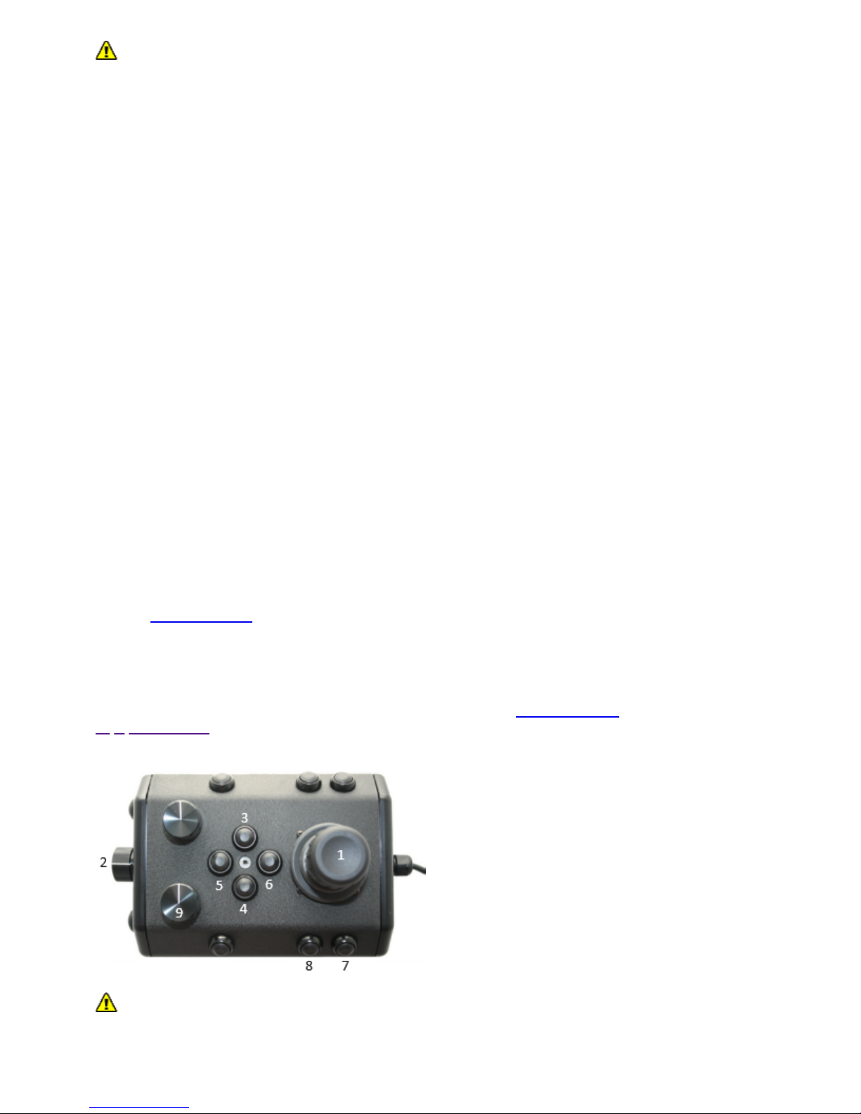
Testing the System's Functions
The next step is to ensure that the essential features of the ROV are functioning properly. Use the
hand controller to perform the following tests. The manipulator functions listed below do not
necessarily represent the full capabilities of the system. See the Hand Controller section of the
Equipment Guide for the complete list of functions and more information about using the hand
controller.
1 Horizontal Control joystick
2 Depth Control knob
3 Camera Tilt Up button
4 Camera Tilt Down button
5 Camera Focus In button
6 Camera Focus Out button
9 Lights Intensity knob
Additional features and controls may be available depending on the system configuration. These
tests represent the minimum set for all configurations.
Test the thrusters
Page 16

For the next two steps, do not operate horizontal thrusters out of water for more than 30
seconds to avoid overheating or premature wear of the cartridge seals.
1. Gently move the joystick forward and backward and left and right - the horizontal thruster
motors should turn the propellers. Release the joystick - it will return to center on its own, and
the propellers will stop turning.
2. Rotate the Depth Control knob - the vertical thruster motor should turn the propeller. Return the
Depth Control knob to center to cease the vertical propeller rotation.
Test the lights
For the next two steps, do not leave the lights on bright for more than 30 seconds while
the ROV is out of water to avoid overheating.
1. Turn the Lights Intensity knob to brighten or dim the lights - the lights intensity should vary
according to the knob's position.
Test the camera functions
1. Press and hold the Camera Tilt Up button - the camera should tilt up smoothly through its entire
range.
2. Press and hold the Camera Tilt Down button - the camera should tilt down smoothly through its
entire range.
3. Press and hold the Camera Focus In button - the camera should focus in smoothly through its
entire range.
4. Press and hold the Camera Focus Out button - the camera should focus out smoothly through
its entire range.
If a manipulator or other accessories are attached, these items should be checked at this time.
Good Advice
The time to catch small problems before they become big problems is during the pre-dive inspection.
Dive Operations
After the previous four pre-dive checks and tests have been completed successfully, you are almost
ready to commence the dive. But, there is one more issue to address that could affect the performance
of the ROV. The ROV is designed to be operated in a near neutrally buoyant configuration, so the last
step before launching your VideoRay is to check the buoyancy, and adjust the ballast if necessary. For
most operations, the buoyancy is optimal when the top of the float block is even with the water surface
and the ROV is level. If the ROV is too buoyant or too heavy, the vertical position may be hard to
maintain or control.
Buoyancy will need to be adjusted for use in fresh water versus salt water and depending upon
whether accessories are used with the ROV.
Buoyancy Check and Adjustment
To determine if the buoyancy is correct, lower the ROV and at least 3 meters (10 feet) of tether into the
water. You can lower the ROV by the tether - it will not hurt the tether because there is Kevlar in it.
Observe the ROV in the water - it should not be floating too high or sink. It should also be floating level
and not tipped to one side or pitched up or down. If the ROV floats too high, you will need to add some
ballast weights. If the ROV sinks, you will need to remove some ballast weights. If the ROV is not
floating level, you can change the locations of the weights.
Page 17

The buoyancy can be adjusted by adding or removing the supplied ballast weights to the vehicle. The
weights can be added to or removed from the slots by hand. For most operations, the weights should
be evenly distributed to provide a balanced attitude of the ROV in water.
Commence the Dive
Once the buoyancy has been adjusted the ROV is ready to launch. Lower it into the water and operate
the controls to maneuver it. The ROV can be lowered using the tether.
Start with the ROV on the surface and push the joystick forward slightly to make the ROV move
forward. Move the joystick to the left or right to make it turn left or right. Get a feel for how agile
the ROV is.
Observe the video display as well as the ROV to become acquainted with the camera's wide
angle lens and its affect on depth perception underwater.
Once you feel comfortable with the horizontal maneuverability of the ROV, rotate the depth
control knob to dive the ROV. Tilt the camera down as you dive so you can see towards the
bottom. Rotate the depth control knob to bring the ROV back to the surface. Tilt the camera up
as you surface so you can see towards the surface.
Change the lights settings, and adjust the camera focus. If you have a manipulator, tilt the
camera down so you can see it and open and close the jaws.
As you get familiar with maneuvering the ROV, you can start to observe some of the on-screen
displays including the depth, heading, camera settings and other data.
For your first dives, practice until you are comfortable operating the controls without looking at them
and you are able to control the ROV with some precision.
See the Hand Controller section of the Equipment Guide for complete information about using the
hand controller and see the Piloting section of the Operations Guide for more advanced tips on piloting
the MSS.
Automated Flight Operations
Automated flight operations require additional configuration and tuning to ensure accurate flight
dynamics and control. See the Automated Flight Operations section for more details.
Practice Makes Perfect
Developing the skills to operate your MSS like an expert may take some time. Practicing on a regular
basis is highly recommended.
Post-Dive Operations
At the conclusion of your dive, retrieve the VideoRay and power down the system by closing VideoRay
Balefire software, turning off the ROV power switch, shutting down the computer and then turning off
the main power switch.. Make sure the ROV is secure before disconnecting the tether. After
disconnecting the tether, keep the tether connectors clean and do not let them drag on the ground.
Proper maintenance of your VideoRay system ensures a long service life and that it will be ready to
operate when you are. After each dive, you should visually inspect the system for damage that might
have occurred during your operation.
Keeping the ROV clean is one of the most important aspects of good preventative maintenance
practices, especially after using it in salt water. If you use your ROV in salt water, or water with
contaminants, you should first rinse it, and then soak it in clean fresh water for at least one-half hour.
After cleaning the ROV and tether, they should be allowed to air dry before being put away for storage.
Page 18

Failure to properly maintain the ROV by thoroughly cleaning it after use may dramatically
reduce its service life.
Debriefing
Congratulations! You are well on your way to becoming an accomplished micro-ROV operator, but
there are still many things to learn and skills to master. Continue learning about the system by
reviewing the additional sections of this documentation and, most importantly, practice, practice,
practice.
If you encountered any difficulties or have any questions, review these Quick Start Instructions and the
other documentation that came with your system, including the Equipment Guide. If you still have
difficulty or questions, contact VideoRay. Your success is our success, and we are here to help you get
the most out of your VideoRay.
VideoRay contact information is available on the About this Documentation page.
Ready to Learn More?
To accelerate your learning and receive recognition for your knowledge and skills, VideoRay offers inperson classes and online training as well as the Micro-ROV User Certificate program. Training can be
delivered at your site and customized to your needs. To learn more about these opportunities, click on
the training link above to visit the VideoRay Educational Resources website.
ROV System Specifications
Page 19

Open in New Window
MSS Defender features and specifications are subject to change without notice.
Specifications for the ROV Modules
Specifications for the VideoRay M5 Modules are provided on the following pages.
Power Module Specifications
Depth Rating
2,000 meters (6,500 feet)
Mechanical
Dimensions: 18 cm x 13 cm x 4 cm (7.1 inches x 5.1 inches x 1.6 inches)
Weight in Air: 1.14 kg (2.5 pounds)
Weight in Water: 0.55 kg (1.2 pounds)
Connections
8-Pin Male Connector (Tether)
9-Pin Female Connector (Communications)
Page 20

5-Pin Female Connectors (Thrusters and LEDs) 2X
Power Input
Input Voltage Range: 200 - 420 V DC
Power Output
48V: 1500 W
24V: 300 W
12V: 120 W
M5 Power Module features and specifications are subject to change without notice.
Communications Module Specifications
Depth Rating
2,000 meters (6,500 feet)
Mechanical
Dimensions: 25.5 cm x 15.2 cm x 5.3 cm (6.12 inches x 6.0 inches x 2.1 inches) not including
cable
Weight in Air: 1.19 kg (2.6 pounds)
Weight in Water: 0.55 kg (1.2 pounds)
Connections
9-Pin Male Connector (Upstream, Port 1)
9-Pin Female Connectors (Accessories, Ports 2 - 6) 5X
Power Input
24V: 300 W
12V: 120 W
Power Output
24V: 300 W
12V: 120 W
Communications
Ethernet
RS-485
Sensor Feedback
Current Monitoring
Voltage Monitoring
M5 Communications Module features and specifications are subject to change without notice.
AHRS Module Specifications
Depth Rating
2,000 meters (6,500 feet)
Mechanical
Page 21

Dimensions: 17.8 cm x 7 cm x 5.4 cm (7.0 inches x 2.75 inches x 2.12 inches) not including
cable
Weight in Air: 0.55 kg (1.2 pounds)
Weight in Water: 0.21 kg (0.46 pounds)
Connections
9-Pin Female Connector
Power Input
12 VDC
Communications
Ethernet
RS-485
Sensor Feedback
9 DOF IMU
Magnetic compass
RPM
Pressure Based Depth Sensor (100 Bar, with 400 Bar optional)
IMU Features
0.2 degree Static Roll/ Pitch
0.5 degree Dynamic Roll/ Pitch
1.0 degree Yaw
18 degree/h Gyro Bias Stability
M5 AHRS Module features and specifications are subject to change without notice.
Thruster Module Specifications
Depth Rating
2,000 meters (6,500 feet)
Mechanical
Dimensions: 13.2 cm x 12.2 cm x 11.8 cm (5.19 inches x 4.80 inches x 4.64 inches) not
including cable
Weight in Air: 0.65 kg (1.4 pounds)
Weight in Water: 0.33 kg (0.73 pounds)
Connections
5-Pin Male / Female Connector (Stackable)
Power Input
48 VDC at 750-Watt Max input
Communications
RS-485 Galvanically Isolated Control
Sensor Feedback
Input Current Total
Page 22

Input Voltage
RPM
Internal Temperature
Features
Direct Drive Brushless Motor
Several Mounting Options
90mm Diameter Propeller
3 Blade Propeller with quick connect/release Collet
Smooth Start at 120 RPM
Instant Reverse
No Cogging
Very Quiet and Smooth Operation
M5 Thruster Module features and specifications are subject to change without notice.
Camera Module Specifications
Depth Rating
2,000 meters (6,500 feet)
Mechanical
Dimensions: 15.4 cm x 8 cm diameter (6.1 inches x 3.1 inches diameter) not including cable
Weight in Air: 0.66 kg (1.45 pounds)
Weight in Water: 0.9 kg (0.20 pounds)
Connections
9-Pin Female Connector
Power Input
12 VDC; Power Consumption: 57w
Communications
Ethernet
RS485
Sensor Feedback
Internal Pressure/Vacuum Integrity
Internal Humidity
Internal Temperature
Tilt Position
Protocols
Video: Ethernet
Camera Control: Ethernet
Servo Control: RS485
Visibility
Internal Tilt: 85 Degrees
Horizontal Field of View: 80 Degrees
Features
Page 23

Optical BK7 Glass Dome
Autofocus
Whitebalance Control
16x Digital Zoom
13.19 Megapixel Still Capture
M5 HD Camera Module features and specifications are subject to change without notice.
LED Light Module Specifications
Depth Rating
2,000 meters (6,500 feet)
Mechanical
Dimensions: 7.6 cm x 7 cm x 2.8 cm (3.0 inches x 2.75 inches x 1.12 inches) not including cable
Weight in Air: 0.14 kg (0.31 pounds)
Weight in Water: 0.09 kg (0.10 pounds)
Connections
5-Pin Male / Female Connector (Stackable)
Power Input
48 VDC at 76 Watt
Communications
RS-485 Galvanically Isolated Control
Sensor Feedback
Input Voltage
Input Current Total
Internal Temperature
Features
3,000 K CCT, 80 CRI White
2,880 Calculated minimum flux (lm) per array, 5,760 total lm per light module
Individually Controlled Arrays (16 emitters per array, 32 total)
60 Degree Spot Beam
110 Degree Flood Beam
Hard Anodized, Potted Housing
M5 LED Light Module features and specifications are subject to change without notice.
Specifications for the ROV Accessories
Specifications for the VideoRay MSS Defender accessories are provided on the following pages.
Sonar Specifications
Page 24

Page 25

Open in New Window
MSS Defender features and specifications are subject to change without notice.
DVL Specifications
Page 26

Open in New Window
MSS Defender features and specifications are subject to change without notice.
Rotating Manipulator Specifications
The maximum depth rating for the Rotating Manipulator is 300 meters (1,000 feet).
The Rotating Manipulator uses 24 Volts with a maximum current draw of approximately 1 Amp. This
equates to 24 Watts of power consumption.
Jaw Specifications
ROV GPS Specifications
TBA
Page 27

Page 28

MSS
Operator's Manual, 1.00.00
System Voltage Advisory
AC Input
Input voltage is universal at 100-240 VAC; 50, 60 Hz. The power requirement for the MSS operating at
full power settings is 3,000 Watts. A 2,000 Watt source (i.e. generator) can be used if the system will
not be used at full power settings.
ROV DC Power
Historically, the tether voltage to power the ROV has been increasing. Economy models (including the
Scout, Explorer and Voyager), Pro 3 variants and the Pro 4 Ultra use 48 V DC for vehicle power. The
Pro 4 uses 74 V DC. The MSS (Mission Specialist Series) uses 400 V DC with plans to use higher
voltages in the future. Systems with voltages higher than 48 V DC include a LIM (Line Insulation
Monitor) protection module in the ROV DC circuit.
System components should not be connected to voltage sources higher than their rating.
VideoRay Negative, Neutral and PPT tethers are rated to 600 V DC and are safe to use on any system
through the MSS 400 V DC.
The standard TDS and Extended TDS are only rated to 300 V DC and should not be
used with MSS systems or components.
The new version of the extended TDS is available that includes a 600 V rated slip ring.
If you have any questions about system voltage and compatibility, contact VideoRay Support.
Page 29

MSS
Operator's Manual, 1.00.00
Equipment Guide
Understanding the features and capabilities of the MSS equipment is essential to get the most value
out of using the system. The sections within this Equipment Guide provide details about each of the
components.
Topics in this Section
ROV
User Control Console
Page 30

Hand Controller
Tether
Connection Summary
Page 31

MSS
Operator's Manual, 1.00.00
ROV
The MSS ROV consists of modular components (thrusters, lights, cameras, sensors) and a custom
frame. Each MSS vehicle is designed to meet the requirements of a specific underwater mission. The
frame and sensor payload can be optimized to deliver the vehicle to its intended destination and
accomplish the tasks, whether that be recording video, taking measurements of various parameters, or
navigation and remote sensing such as sonar or laser imaging.
The sections that follow provide information about the frame and modular components.
ROV Nomenclature
ROV nomenclature follows the general pattern for seagoing vessels. The image below provides a visual
reference for the directions and attitude relative to the ROV.
Page 32

ROV Orientation and Directions Reference
Bow - The front of the ROV.
Stern - The rear of the ROV
Port - The left side of the ROV when facing forward.
Starboard - The right side of the ROV when facing forward.
Fore - Towards the front or The forward direction.
Aft - Towards the rear of the rearward direction.
Surface - To ascend or move up in the water column to a shallower depth.
Dive - To descend or move down in the water column to a deeper depth.
ROV Attitude and Motion Reference
Surge - Forward and Reverse motion of the ROV, forward is positive.
Heave - Up and Down motion of the ROV, up is positive.
Sway - Left (to port) and Right (to starboard) lateral motion of the ROV, left is positive.
Yaw - Right (to starboard) and Left (to port) rotational motion of the ROV, right (clockwise, viewed from the
top) is positive.
Pitch - Bow Up or Bow Down inclination of the ROV, bow up (clockwise, viewed from the port side) is
positive.
Roll - Port UP or Port Down relative to Starboard, port up (clockwise, viewed from the rear) is positive.
Page 33

Submersible Frame
The MSS frame provides the structure to combine the modular components and accessory payload.
The modular concept allows the MSS frame to be optimized for the specific tasks for which the vehicle
is designed.
Frame Arrangement
The following frame arrangements have been designed.
Alpha Frame
Defender Frame
Pro 5
Buoyancy
The MSS Vehicle's buoyancy can affect performance and should be adjusted for water type (fresh
versus salt), payload and performance requirement.
Buoyancy Arrangement
The desired buoyancy of the vehicle is achieved by using a combination of modular flotation and
ballast weights.
Ballast
The MSS Vehicle's buoyancy can affect performance and should be adjusted for water type (fresh
versus salt), payload and performance requirements.
Ballast Arrangement
The desired buoyancy of the vehicle is achieved by using a combination of modular flotation and
ballast weights.
Power Module
The Power Module receives power from the topside and converts it to power levels required by the
various modules, sensors and accessories.
Page 34

8 Pin Male Tether Connector
Pin Function
1 Interlock (GND)
2 Interlock (Sense)
3 Tether V+
4 M100 EOP+
5 Tether V-
6 M100 EOP-
7 RS-485 A
8 RS 485 B
5 Pin Female High Power (Thruster, Lights) Connector (2)
Pin Function Wire AWG Color
1 48 V DC + 20 Red
2 GND 22 Green
3 48 V DC - 20 Black
4 RS-485 A 24 Gray
5 RS-485 B 24 White
Power is rated at 750 Watts per port for 1,500 Watts total.
9 Pin Female Communications Module Interface Connector
Page 35

Pin Function
1 NC
2 NC
3 24 V DC +
4 M100 EOP +
5 GND
6 M100 EOP -
7 RS-485 A
8 RS-485 B
9 12 V DC +
Power is rated at 300 Watts for the 24 Volt circuit and 120 Watts for the 12 Volt circuit.
Power Module Arrangement
The MSS Power module is usually located at the rear of the vehicle, but can be installed in the optimal
location for the specific vehicle.
Communications Module
The communications module is the "brains" of the vehicle and coordinates vehicle control systems and
provides data paths for sensors and accessories.
Page 36

9 Pin Interface Connectors
Pin Male Connector (port 1) Female Connectors (ports 2-6)
1 NC ETH_RXP +
2 NC ETH_RXP -
3 24 V DC + 24 V DC +
4 M100 EOP + ETH_TXP +
5 GND GND
6 M100 EOP - ETH_TXP -
7 RS-485 A RS-485 A
8 RS-485 B RS-485 B
9 12 V DC + 12 V DC +
Power is rated at 300 Watts each for the 24 and 12 Volt circuits.
Communications Module Arrangement
Communication Module is configurable.
Page 37

AHRS Module
AHRS - Attitude and Heading Reference System
The AHRS is also sometimes referred to as an Inertial Measurement Unit, or IMU. It provides feedback
on the vehicle's orientation. Measurements include magnetic heading, attitude and rates of change.
The AHRS also includes a pressure sensor to determine the depth of the vehicle.
Cable Pinout
Pin Function
1 ETH_RXP +
2 ETH_RXP -
3 24 V DC +
4 ETH_TXP +
5 GND
6 ETH_TXP -
7 RS-485 A
8 RS-485 B
9 12 V DC +
AHRS Module Arrangement
The AHRSD is typically mounted in the top center of the ROV frame.
Thruster Module
MSS vehicles use a modular thruster configuration that allows vehicle designs to be optimized for
water conditions and payload delivery requirements. Modular thrusters are also easy to replace in the
field.
Page 38

Thruster Propeller
The propellers are designed to be used on counter-rotating thruster arrangements to eliminate torque
roll or yaw. Propellers are identified by their pitch orientation using left and right based on their pitch.
The convex edge of the propeller blade is the leading edge during motion that is considered forward
for that thruster.
Right-hand propellers can be identified as follows:
The top blade has the leading edge on the right when viewed from the end with the nut.
The blades appear to curve counterclockwise when viewed from the end with the nut.
Right hand propellers have a stainless steel collar on the hub at the shaft end.
Left-hand propellers can be identified as follows:
The top blade has the leading edge on the left when viewed from the end with the nut.
The blades appear to curve clockwise when viewed from the end with the nut.
Left hand propellers have hub that is all plastic.
Page 39

Cable Pinout
The Thruster connector uses a male / female stackable connector allowing the thrusters and LED
lights to be connected in series.
Pin Function Wire AWG Color
1 48 V DC + 20 Red
2 GND 22 Green
3 48 V DC - 20 Black
4 RS-485 A 24 Gray
5 RS-485 B 24 White
Thruster Arrangement
The Thruster modules can be located within the vehicle frame and configured as required for the
specific vehicle.
Alpha Frame Thrusters
The MSS vehicle is an Alpha frame that uses a vectored horizontal thruster arrangement, and two
vertical thrusters. The thrusters are configured as shown below:
Thruster
Location
Propeller
Orientation
Reverse
Option
GroupIDNodeIDMotor
ID
TCP/IP
Address
TCP/IP
Port
Notes
Forward Port Right Disabled 129 5 0 192.168.1.64 1 (7444)
Forward
Starboard
Left Enabled 129 6 1 192.168.1.64 1 (7444)
Aft Starboard Right Disabled 129 7 2 192.168.1.64 1 (7444)
Aft Port Left Enabled 129 8 3 192.168.1.64 1 (7444)
Forward
Vertical
Right Disabled 129 9 4 192.168.1.64 1 (7444)
Aft Vertical Left Enabled 129 10 5 192.168.1.64 1 (7444)
Defender Frame Thrusters
The MSS vehicle is a Defender frame that uses a vectored horizontal thruster arrangement, and three
vertical thrusters. The thrusters are configured as shown below:
Thruster
Location
Propeller
Orientation
Reverse
Option
GroupIDNodeIDMotor
ID
TCP/IP
Address
TCP/IP
Port
Notes
Page 40

Forward Port Right Disabled 129 5 0 192.168.1.64 1 (7444)
Forward
Starboard
Left Enabled 129 6 1 192.168.1.64 1 (7444)
Aft Starboard Right Disabled 129 7 2 192.168.1.64 1 (7444)
Aft Port Left Enabled 129 8 3 192.168.1.64 1 (7444)
Forward
Vertical Port
Right Disabled 129 9 6 192.168.1.64 1 (7444)
Forward
Vertical
Starboard
Left Disabled 129 10 4 192.168.1.64 1 (7444)
Aft Vertical Left Enabled 129 20 5 192.168.1.64 1 (7444)
Pro 5 Frame Thrusters
The MSS vehicle is a Defender frame that uses a vectored horizontal thruster arrangement, and three
vertical thrusters. The thrusters are configured as shown below:
Thruster
Location
Propeller
Orientation
Reverse
Option
GroupIDNodeIDMotor
ID
TCP/IP
Address
TCP/IP
Port
Notes
Port Right Disabled 129 5 0 192.168.1.64 1 (7444)
Starboard Left Enabled 129 6 1 192.168.1.64 1 (7444)
Vertical Right Disabled 129 7 2 192.168.1.64 1 (7444)
Camera Module
The camera module provides a live video feed from the vehicle to the surface.
Page 41

Cable Pinout
Pin Function
1 ETH_RXP +
2 ETH_RXP -
3 24 V DC +
4 ETH_TXP +
5 GND
6 ETH_TXP -
7 RS-485 A
8 RS-485 B
9 12 V DC +
Camera Arrangement
The following cameras have been designed.
High Definition Camera
Low Light Camera
High Definition Camera
Page 42

High Definition Camera
Low Light Camera
Low Light Camera
LED Light Module
The LED Light Module provides variable levels of illumination and beam pattern control.
Cable Pinout
The LED Light connector uses a male / female stackable connector allowing the LED lights and
thrusters to be connected in series.
Pin Function Wire AWG Color
1 48 V DC + 20 Red
2 GND 22 Green
3 48 V DC - 20 Black
4 RS-485 A 24 Gray
5 RS-485 B 24 White
Page 43

Lights Arrangement
The Light modules can be located within the vehicle frame and configured as required for the specific
vehicle.
Multiple LED Light Modules can be used.
Alpha Frame Lights
The MSS vehicle is an Alpha frame that uses a single Light Module. The Light Module is configured as
shown below:
Light Location Group ID Node ID Application ID TCP/IP Address TCP/IP Port Notes
Front top center 131 11 0 192.168.1.64 1 (7444)
Defender Frame Lights
The MSS vehicle is an Alpha frame that uses two Light Modules. The Light Modules are configured as
shown below:
Light Location
Group
ID
Node
ID
Application
ID
TCP/IP Address TCP/IP Port Notes
Front Top Port 131 11 0 192.168.1.64 1 (7444)
Front Top
Starboard
131 11 0 192.168.1.64 1 (7444)
Pro 5 Frame Lights
The MSS vehicle is an Alpha frame that uses two Light Modules. The Light Modules are configured as
shown below:
Light Location
Group
ID
Node
ID
Application
ID
TCP/IP Address TCP/IP Port Notes
Front Top Port 131 11 0 192.168.1.64 1 (7444)
Front Top
Starboard
131 12 0 192.168.1.64 1 (7444)
ROV Connections
The MSS ROV system uses 3 types of connectors for power and communications between the control
panel, vehicle modules and accessories.
8 Pin Tether Connector
Pin Function
1 Interlock (GND)
2 Interlock (Sense)
3 Tether V+
4 M100 EOP+
5 Tether V-
6 M100 EOP-
7 RS-485 A
8 RS 485 B
Page 44

Pin numbering starts at 1 for the offset pin and is clockwise on the male connector and counter
clockwise on the female connector.
5 Pin Thrusters and Lights Connector
Pin Function
1 48 V DC +
2 Vehicle Local Ground (12 V, 48 V return)
3 48 V DC return
4 RS-485 A
5 RS-485 B
Pin numbering is clockwise starting at 1 in the upper left when looking at the face of the male
connector with the row of 3 pins on top.
9 Pin Accessory Connector
Pin Function
1 ETH_RXP-
2 ETH_RXP+
3 24 V DC +
4 ETH_TXP +
5 Ground
6 ETH_TXP -
7 RS-485 A
8 RS-485 B
9 12 V DC +
Pin numbering is clockwise starting at 1 in the upper left when looking at the face of the male
connector with the row of 5 pins on top.
ROV Connections
Tether Strain Relief
Page 45

The strain relief is used to secure the ROV to the tether to prevent separation and loss of the vehicle if
the tether connection becomes disconnected. The strain relief also minimized the load on the tether
connector.
Page 46

MSS
Operator's Manual, 1.00.00
User Control Console
The User Control Console provides power, communications and a video interface between the surface
and the ROV through the tether. The computer, which runs software to control the ROV, is housed in
the User Control Console along with a display monitor .
User Control Console Power Specifications
The VideoRay MSS operates on typical residential power in the range of 100-240 Volts AC, 50,60 Hz.
This can be provided from the land-based grid, a generator, or a battery with an inverter (optional). The
typical power requirements for operating from a generator or inverter are 3,000 Watts continuous
minimum.
The system includes a GFCI (Ground Fault Circuit Interrupter) / Circuit Breaker to protect the operator.
The power in the tether is 400 Volts DC. This circuit is protected by a LIM (Line Insulation Monitor).
The procedures for testing the circuit safety components can be found in the Pre-Dive Preparations
section of the Quick Start Instructions.
Do not block the User Control Console fans. Blocking the fans can lead to overheating
and component failure.
Display Monitor Tilt Arm
Page 47

The Display Monitor Tilt Arm on the left side of the User Control Console can be used to adjust the
angle of the User Control Console lid and monitor. To adjust the angle of the monitor, loosen the
locking collar, adjust the lid to the desired angle and tighten the locking collar.
Make sure to loosen the display monitor tilt arm before closing the User Control Console
lid, and be careful when closing the lid to avoid damaging the computer or monitor or pinching any
cables.
Safety Circuits
The User Control Console includes three safety circuit components.
GFCI (Ground Fault Circuit Interrupter)
LIM (Line Insulation Monitor)
ROV Power Safety Interlock
GFCI (Ground Fault Circuit Interrupter)
The GFCI protects the operator from shock from the AC circuit of the power source.
The GFCI is inline with the power cord. When initially connected to a power source, it is in the Off state.
You must press the Reset Button to enable it. When enabled, the green LED will be illuminated.
When using a power source that includes a GFCI, the VideoRay supplied GFCI is not needed and
can be removed from the power cord.
LIM (Line Insulation Monitor)
The LIM protects the operator and persons in the water nearby from shock from the DC circuit of the
tether. While the GFCI switches are part of the GFCI component and must be turned on to operate the
User Control Console, the LIM is automatically enabled when the system is turned on. The LIM
operates on a principle similar to the GFCI and monitors the quality of the insulation of the conductors.
If the resistance between the conductors drops below the safe threshold, the LIM will trip.
The MSS LIM is two stage. When the LIM detects the resistance between the ROV power conductors
falls below 900 kOhms, the yellow LIM Alarm A1 LED will turn on, but the power circuit will remain on.
When the LIM detects the resistance falls below 200 kOhms, the yellow LIM Alarm A2 LED will turn on
and the ROV power circuit will be disabled. The LIM can be reset by pressing and holding the R button.
The yellow LIM Alarm light should turn off. To test the LIM, press and hold the T button. If the LIM
continues to trip, the system should be inspected for a fault before being used.
Page 48

The LIM has additional features that are described in more detail in the LIM Module Manual.
ROV Power Safety Interlock
The ROV Power Safety Interlock prevents the ROV power from being engaged unless an ROV is
plugged into the tether. This feature protects users from accidentally contacting the ROV power circuit
of an open tether connector.
See the User Control Console Switches and Connections section for more information about these
components and their locations, and see the Pre-Dive Preparations section of the Quick Start
Instructions for information about testing these components.
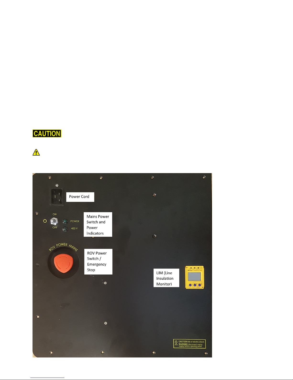
Switches and Connections
The User Control Console top includes the following switches:
SWITCH LOCATION FUNCTION
Main
Power
Switch
User Control
Console top upper
left
Turns the User Control Console on and off.
Page 49

ROV
Power
Switch
User Control
Console top central
left
Turns the ROV power on and off. Twist in the direction of the arrows
to turn on the ROV power and press the switch to turn it off.
LIM
Module
User Control
Console top central
right
Test and Reset buttons can be found on the LIM.
The User Control Console top includes the following connections:
CONNECTION LOCATION FUNCTION
Power (100-240 Volts AC, 50, 60
Hz)
IEC male Used to connect the User Control Console to a power
source.
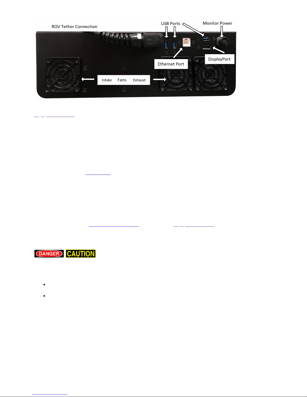
The User Control Console side includes the following connections:
CONNECTION TYPE FUNCTION
Tether Whip
(Specifications)
8 pin round
female
Used to connect the User Control Console to the tether for power,
communications, video and accessory support.
Monitor Power Provides 12 Volts DC. Used to provide power to the monitor.
Monitor Signal Display Port
Female
Used to provide the video signal to the monitor.
USB Ports (3) Type A
female
Can be used to connect USB devices to the computer via the User
Control Console.
Ethernet RJ-45
female
Can be used to connect the User Control Console to the computer for
Ethernet based ROV accessories.
The Display Port cable uses a locking locking connector. Make sure to press the release button
when disconnecting the cable to avoid damaging the connector.
Computer
The computer provides the hardware and operating system platform for VideoRay ROV control
software and image and video editing and production. The computer is embedded in the User Control
Console.
For information about using the computer in general, see the instructions that came with it.
VideoRay does not recommend installing additional hardware or software on the computer unless
you are familiar with its operation and confident it will not interfere with the VideoRay control software
or the computer's ports. Software that is packaged with VideoRay accessories has been tested and is
approved for use.
Page 50

The computer includes the following connections (which are passed through to connectors on the User
Control Console):
CONNECTION TYPE FUNCTION
USB (3) Type A
female
Can be used to connect USB devices to the computer.
Ethernet RJ-45
female
Can be used to connect the computer to a network, or the User
Control Console for Ethernet based accessories.
Display Port Display Port
Female
Provides an HD video signal. This can be used to connect the
computer to an external monitor.
Additional Specifications
Operating System
Ubuntu
Temperature
Operating Temperature: -40 C - 70C
Storage Temperature: -40 C - 85C
Power Input
9 - 48 VDC
Hard Disk Space
256 Gb
Computer specifications are subject to change without notice.
HD Monitor
The display port cable has a latching connector. Make sure to press the latch button
before trying to remove the connector.
The monitor includes a brightness knob.
The monitor includes the following connections:
CONNECTION Type FUNCTION
Power 12 VoltDCUsed to connect the monitor to a power source. The control panel provides
a matching 12 Volt DC connector.
Display Port In Display
Port
Used to connect the monitor to the computer.
Additional Specifications
Size
18.5" Diagonal
Power Input
12 VDC
Native Resolution
1920 X 1080
Page 51

Brightness
High Bright � 1000 nits
Features
Wide Viewing Cone
10 Point PCAP Touch
Front Full Range Diming Pot
Monitor specifications are subject to change without notice.
Page 52

MSS
Operator's Manual, 1.00.00
Hand Controller
The hand controller is used to operate the VideoRay and its features. Several types of hand controllers
are supported. Controllers not included in your configuration are available from VideoRay for
purchase. Supported controllers include:
VideoRay Industrial Hand Controller
VideoRay IP65 Hand Controller
Logitech Wired or Wireless Gamepad Hand Controller
The hand controller functions are described in more detail in the following pages of this guide.
Hand Controller Compatibility
Any Microsoft® Windows® compatible game controller can be used with the MSS, but each controller
requires a configuration file to map the joystick, buttons and knobs to the ROV functions.
Page 53

Microsoft is a registered trademark of Microsoft. Windows is a registered trademark of Microsoft.
Logitech is a registered trademark of Logitech.
Page 54

MSS
Operator's Manual, 1.00.00
Tether
Tether connects the ROV to the surface and provides power, communications, video and an APIC
(Auxiliary Pair of Independent Conductors) for accessory use. The tether consists of conductors, a
Kevlar® strength member, flotation (for Neutral and Performance tethers) and an outer jacket. It is
available three types: Negative, Neutral and Performance (often called PPT), and can be purchased in
standard and custom lengths. Neutral and Performance are neutrally buoyant in fresh water because
they have a specially designed foam jacket.
While larger conductors provide the best power transmission capacity, they lead to thicker tethers,
which results in higher drag. Negative tether has the largest conductors (best power transmission
capacity), followed by Neutral, and then Performance. Negative and Performance tether have the
smallest diameter (least drag), while Neutral tether has the largest diameter.
The tether connectors are wet mateable and can be connected while they are wet. One of the pins in
the connector is offset. To connect the tether to the ROV, control panel or another tether, align the
offset pin of the connectors and press the two connectors together until the base surface of each
connector are touching each other. Then, connect the tether locking sleeves by screwing them
together to secure the connection.
Multiple tethers can be connected in series like conventional power extension cords. See the Tether
Management section of the Operations Guide for recommended tether configurations.
Always secure the tether connectors using the locking sleeves and strain relief system to
avoid separation and loss of the ROV.
Page 55

The strain relief system includes a carabineer that could get hooked on something underwater and
cause the ROV to become trapped. To avoid this possibility, tape over the carabineer with electrical or
duct tape.
The tether connectors should be kept clean to avoid abrasion and corrosion on the
electrical contacts and damage to the rubber insulation. Tether connectors should not be lubricated
with petroleum products or grease. Petroleum will degrade the rubber and grease will attract dirt and
lead to abrasion and corrosion. VideoRay recommends lubricating the tether connectors with pure
silicone spray.
Tether Specifications
Tether Diameter
Units \ Type Negative Neutral Performance
mm 8.51 +/- 0.38 11.18 +/- 0.50 8.18 +/- 0.50
inches 0.335 +/- 0.015 0.440 +/- 0.020 0.322 +/- 0.020
Minimum Tether Bend Radius
Units \ Type Negative Neutral Performance
mm 88.9 114 82.5
inches 3.5 4.5 3.25
Tether Connector Pin Configuration
Tether pin numbering in the connector is shown above. When looking at the mating surface of the
connector, Pin 1 is the offset pin / socket. For male connectors, pins 2-8 proceed in a clockwise
direction. For female connectors, sockets 2-8 proceed in a counter-clockwise direction.
Tether Pin Function and Conductor Wire Gauge
Pin Function Negative Neutral Performance
1 Interlock (GND) 24 24 28
2 Interlock (Sense) 24 24 28
3 400 VDC + 16 (x2) 20 (x2) 24 (x2)
4 M100 EOP+ 24 28 28
5 Ground 16 (x2) 20 (x2) 24 (x2)
6 M100 EOP- 24 28 28
7 RS-485 A 24 28 28
Page 56

8 RS-485 B 24 28 28
All conductors are straight through, such that pin 1 in the male connector is connected to socket 1
in the female connector, and so on for all eight pins / sockets.
Tether Buoyancy
Performance and Neutral tether includes buoyancy compensating foam that provides near neutral
buoyancy in fresh water. Negative tether contains no foam and will sink. The connectors do not contain
any buoyancy compensation and will sink.
Tether Strength
All tether types include Kevlar that is rated at 450 kg (1,000 pounds), the connectors are rated 80 kg
(175 pounds).
These values are breaking strength. The tether should not be subjected to a working
strength greater than one half of the breaking strength. The ROV and tether are equipped with a strain
relief cable and connectors, which are rated at 136 kilograms (300 pounds). The strain relief cable
should be used to avoid separation of the tether connectors and loss of the ROV.
The maximum usable tether length is limited by the ability of the tether to transmit power and data
signals. The maximum usable tether length of MSS systems is about 550 meters (1,800 feet). MSS
systems can fiber tether to extend the range. See the Tether Management section of the Operations
Guide for more information.
Kevlar is a registered trademark of E. I. du Pont de Nemours and Company
Page 57

MSS
Operator's Manual, 1.00.00
Connections Summary
The following connections are required:
1. Connect the female end of the tether to the ROV.
2. Secure the tether strain relief to the ROV.
3. Connect the male end of the tether to the User Control Console.
4. Connect the keyboard to a USB port on the User Control Console.
5. Connect the hand controller to a USB port on the User Control Console.
6. Connect the power cord to a suitable power source.
Page 58

MSS
Operator's Manual, 1.00.00
Accessories
Numerous accessories can be used with the MSS to extend its capabilities and range of performance.
These accessories allow the MSS
Multiple accessories can be connected in parallel by the use of a stackable connector. The
manipulator and cutter do not use a stackable connector, but can be used with other accessories by
plugging in their connector as the last one in sequence.
The accessory port must be sealed with a terminated accessory connector or the
accessory port terminator dummy plug. Failure to seal the accessory port may lead to loss of control of
the ROV or damage to the components.
Included Accessories
Several topside accessories are included with all MSS system configurations.
Sun Shade
The sun shade can be attached directly to the control panel lid and provides shade for the computer
and monitor to make it easier to see the displays when working in bright light. See the label on the sun
shade for installation instructions.
Tool Kit
A basic tool kit is provided in order to perform routine maintenance and field repairs. The tool kit also
contains some spare parts including ballast weights, propellers and other items.
Additional Sensors and Tooling
This configuration includes the following sensors and tooling:
Mission Support Accessories
In addition to the equipment that is included with each MSS configuration and the commercially
available accessories, VideoRay recommends users procure a variety of mission support items. The
list of recommended items will vary depending on the typical mission requirements, although it will be
obvious that some of these items have general applicability to all mission profiles.
These brief lists are intended to provide a sample and stimulate thinking about what you might want to
add to your "operations kit:"
General Logistical Support
Basic operations support items including tables and chairs, foul weather gear, food, water, etc.
Power sources including generators and batteries/inverters
Supplemental video display devices for large group viewing (this can help prevent people from
hovering over and distracting the pilot)
Supplemental tools, such as a flashlight, knife, tape, cable ties, etc.
Supplemental spare parts for field repairs (Basic spares are included for some items)
Tactical Operations Support
Tether weights and davit
Page 59

Retrieval devices or baskets
In general, VideoRay does not supply these items, and users must procure them on their own.
Page 60

MSS
Operator's Manual, 1.00.00
Software Guide
MSS software consists of three main components:
1. Topside User Interface, installed on the User Control Console and used to control the ROV.
2. Configuration and diagnostic software installed on the User Control Console used to configure
and test each ROV module.
3. Module Firmware installed on each module to allow the module to perform its functions.
The topside user interface software is available in several versions:
1. Greensea Systems Inc., with fully autonomous capabilities
2. VideoRay basic interface
3. User developed software
Page 61

MSS
Operator's Manual, 1.00.00
Greensea Systems Interface Overview
Greensea's EOD Workspace is the topside control software for the MSS.
To Start VideoRay EOD Workspace, double click on the MSS icon on the desktop.
For more information about Greensea's VideoRay EOD Workspace software, see the Greensea
Operator's Manual. For the most recent information, visit Greensea's Knowledge Base (Login Required -
free to request).
To obtain a login for the Greensea Knowledge Base, contact support@greenseainc.com or call +1
802-434-6080.
Page 62

MSS
Operator's Manual, 1.00.00
VideoRay Interface Overview
There are four applications that are required to operate the VideoRay vehicle control software. These
are stored in the ~/Flighthack folder.
Start the thruster controls using vr_engage.py
Start the camera controls using vr_engage_camera.py
Start the video window
Video is automatically in record mode when the video window is started.
When stopping video, you must enter CTRL-C in the text window to close the file properly.
Start the manipulator controls (optional) using vr_engage_manip_rotating.py
Each application may be started in any sequence, but following a consistent sequence such as above
is recommended.
Page 63

MSS
Operator's Manual, 1.00.00
Software Management
This section provides information about the software environment and managing the software.
Folder Structure
Home/ - User Root Folder
firmware/ - Module Firmware
flighthack/ - MSS Utilities
gss_config/ - Configuration Files
gss_logs/ - Recordings
gss_mission/ - Mission Definition Files
Page 64

MSS
Operator's Manual, 1.00.00
Module Configuration
The modular concept requires that modules be configured prior to installation or replacement in a
specific vehicle arrangement.
Configuration information is specific to each vehicle. Information about the configuration for a
specific vehicle can be found in the Submersible section of the Equipment Guide.
Conceptual Overview
Thrusters and other modules can be thought of as employees, and the vehicle as the jobsite. Each
employee (Module) has a unique name (Serial Number stamped or printed on the module and coded
in the firmware). When the employee goes to work at the jobsite (is installed on the vehicle), it is
assigned an employee number (Node ID) by the person doing the configuration. The jobsite supervisor
(control software) communicates with the employees using their employee number, so the employee
number for each module on a jobsite must be unique. Work instructions are announced to all
employees at the same time, so each employee must listen for their specific instructions and ignore
the instructions for other employees. When there are multiple employees of the same type on a
jobsite, these employees may be assigned specific work tasks (Application ID or Motor ID). The
employee will only listen for instructions related to their work task. For example a starboard thruster
will only respond to horizontal control inputs, while a vertical thruster will only respond to vertical
control inputs. This approach allows vehicles to be configured with great flexibility. Examples include:
A vehicle can be configured with one LED light, or with multiple LED lights. Multiple LED lights
can be controlled in unison, or divided into banks that operate independently.
A vehicle can be configured with a single vertical thruster, or additional vertical thrusters can be
added to create a heavy lift vehicle, or to enable pitch and roll control.
General Requirements
1. Each employee (Module) must have a unique name (Serial Number).
2. Each employee (Module) must have a unique employee number (Node ID) on a jobsite
(vehicle), but different vehicles may use repeated Node IDs.
3. Some employees (Modules) may be assigned specific work tasks (Application ID or Motor ID).
4. At a specific jobsite (Vehicle) more than one employee (Module) may be assigned the same
work task (Application ID or Motor ID).
5. Modules may have additional parameters that can be configured that can affect their operation
or performance, such as temperature cut-off, RPM limit or calibration values.
The following sections provide information about module replacement.
Configuration Commands
The following configuration commands are available for updating firmware and configuring M5
modules for MSS vehicle systems:
vr_refresh - Refresh the firmware for a module
vr_enum - Enumerate (list) the connected modules
vr_setid - Set the Node ID and Group ID for a module
vr_debug_putty.py - Debug and/or configure a module
vr_create_virtport_all.sh - Create virtual ports for modules not connected directly to the RS-
485 bus
More information about using these commands can be found in the following section of this guide.
Page 65

Command: vr_refresh
The vr_refresh command is used to update the firmware on a module.
Use
vr_Refresh [OPTIONS] [SINGLE_HEX_FILE_NAME]
[Options] - See the table below
[SINGLE_HEX_FILE_NAME] - The file name of the firmware update, including its path.
OPTION Alternate Argument(s) Description Default
-? --help Display this help information
--version Display the Version Number
-c --com Com_Port_Name Com port to use dev/ttyUSB0
-i --id Node_ID Node ID of the Module to update, use
255 for broadcast to all nodes
255
--sn Serial_Number The Serial Number any
--block_size Block_Size The block size of the firmware 1024
--timeout Timeout Set the connection Timeout in mS 1500
--
skip_bootcheck
Skip sending a bootcheck command
--
skip_initial_reset
Skip sending an initial reset command
-v --verbose Output verbose diagnostics
-r --reset Reset device upon completion
--UNLOCK Allow programming of the bootloader
---input_file Filename The file name of the firmware update
file, including its path
Some of the options use two dashes "--," not a long dash
Updating Firmware
To use vr_refresh on modules connected to the communications module, you need to open a
virtual port and specify the port to use. See vr_create_virtport_all.sh for more information.
Example firmware update commands for different modules (in each case, X.Y.Z should be replaced by
the actual version number):
Power Module
vr_refresh -i 1 ~/firmware/power_converter-X.Y.Z.hex --block_size 16384
Communications Module
vr_refresh -i 2 ~/firmware/comms_hub-X.Y.Z.hex --block_size 16384
AHRS Module
vr_refresh -c vrport2 -i 3 ~/firmware/attitude_sensor-X.Y.Z.hex --block_size 16384
Thruster Module (Use the correct Node ID)
vr_refresh -i 5 ~/firmware/motor_controller-X.Y.Z.hex
Page 66

Camera Module
vr_refresh -c vrport3 -i 4 ~/firmware/camera_adapter-X.Y.Z.hex --block_size 16384
LED Module (Use the correct Node ID)
vr_refresh -i 11 ~/firmware/led_controller-X.Y.Z.hex
Firmware Block Sizes
Module Block Size Comms Path
Power Module 16384 Direct
Communications Module 16384 Direct
AHRS Module 16384 vport2
Power Module Default Direct
Camera Module 16384 vport3
LED Module Default Direct
Command: vr_enum
The vr_enum command is used to enumerate (list) the modules that are connected to the vehicle.
Use
vr_enum [OPTIONS] [min explcit id] [max explicit id]
[Options] - See the table below
[min explicit id] - The minimum Node ID to include the list
[max explicit id] - The maximum Node ID to include in the list
OPTION Alternate Argument(s) Description Default
-? --help Display this help information
--version Display the Version Number
-c --com Com_Port_Name Com Port to use dev/ttyUSB0
-p --pretty Use nicer human readable device type
display
-v --verbose Output verbose diagnostics
--timeout Timeout Connection timeout in mS 1,000
- --
retry_count
Retry_Count Set retry count for broadcast
enumeration
5
--explicit either max_node_id or
min_node_id
max_node_id
Explicit nodes to search,
Examples
To use vr_enum on modules connected to the communications module, you need to open a virtual
port and specify the port to use. See vr_create_virtport_all.sh for more information.
For Power, Communications, Thrusters and LEDs
vr_enum
For the AHRS and camera modules, you need to include the virtual port.
AHRS Module
Page 67

vr_enum -c vrport2
Camera Module
vr_enum -c vrport3
Some of the options use two dashes "--," not a long dash
Command: vr_setid
The vr_setid command is used to set the Node_ID and Group_ID of a module.
Use
vr_setid [OPTIONS] SN Node_ID Group_ID
SN - See the table below
Node_ID - The Node ID to program into the module (1 - 255)
Group_ID - The Group ID to program into the module (1 - 255)
OPTION Alternate Argument(s) Description Default
-? --help Display this help information
--version Display the Version Number
-c --com Com_Port_Name Com port to use dev/ttyUSB0
--
arguments
Node_ID
Group_ID
The Node_ID (1 - 254) and the Group_ID (1 -
254)
to program into the module
Examples
To use vr_enum on modules connected to the communications module, you need to open a virtual
port and specify the port to use. See vr_create_virtport_all.sh for more information.
For the examples below, replace "S.N" with the actual serial number. The serial number is case
sensitive.
Power Module
vr_setid S/N 1 196
Communications Module
vr_setid S/N 2 193
AHRS Module
vr_setid S/N -c vrport2 3 194
Thruster Module (Use the correct Serial Number and Node ID)
vr_setid S/N 5 129
Camera Module
vr_setid SN -c vrport3 4 196
LED Module (Use the correct Serial Number and Node ID)
vr_setid S/N 11 131
Page 68

Some of the options use two dashes "--," not a long dash
Command: vr_debug_putty.py
The vr_debug_putty.py command is used to configure or test a module.
Use
./vr_debug_putty.py [OPTIONS] [N [N...]]
[Options] - See the table below
N - The Node ID of the module to reset and enter debug mode.
This command must be executed from the flighthack folder and requires the preceding "./"
OPTION Alternate Argument(s) Description Default
-? --help Display this help information
-c --com Com port to use dev/ttyUSB0
Power Module
vr_debug_putty.py 1
Communications Module
vr_debug_putty.py 2
AHRS Module
vr_debug_putty.py -c vrport2 3
Thruster Module (Use the correct Node ID)
vr_debug_putty.py 5
Camera Module
vr_setid SN -c vrport3 4
LED Module (Use the correct Node ID)
vr_debug_putty.py 11
Some of the options use two dashes "--," not a long dash
Command: vr_create_virtport_all.sh
The vr_create_virtport_all.sh command is used to create virtual ports that allow the Ethernet protocol
to be used to communication with modules connected to the communications module.
Virtual Ports
MSS communications are supported using Ethernet and RS-485 protocols. Modules may use one
protocol or the other, or both. The configuration commands described on the previous page, including
vr_enum, vr_setid, vr_refresh and vr_debug_putty.py use only the RS-485 protocol. For modules that
only support Ethernet, a virtual port must be set up to bridge the RS-485 to Ethernet for the
Communications Module port to which the device is attached. The vr_create_virtport_all.sh can be
used to create the required virtual ports.
Page 69

Use
./vr_create_virtport_all.sh &
There are no arguments for this command.
This command must be executed from the flighthack directory and requires the preceding "./"
The trailing "&" allows this command to run in the background, otherwise you would need to open
a new terminal window to use commands that access the virtual ports. When finished using the virtual
ports, they should be removed using the following command: killall socat.
Example Using Virtual Ports to Communicate with a Camera
This example assumes that a Camera Module with serial number CAMADP000123 is plugged into port
2 of the Communications Module.
1. Connect and power up the system, but do not start the control software.
2. Launch the terminal program and use the following commands to access the camera.
3. Navigate to the working folder, type: cd flighthack
4. Enumerate the modules on the system, type: vr_enum You will notice that the camera does not
show up in the list of enumerated modules.
5. To create the virtual ports, type ./vr_create_virtport_all.sh &
6. Now, when you enumerate the modules using vr_enum, the camera and any other non-RS-485
devices should show up in the list. You can also see the virtual ports using the standard
directory listing command, ls
7. To send a commands to the camera, you need to include the -c portNumber option, where the
portNumber to use is the one to which the device is attached on the Communications Module (in
this case port 2, so vrport2).
To set the Node_ID and Group ID:
vr_setid -c vrport2 CAMADP000123 4 196
To enter Debug mode:
./vr_debug_putty.py -c vrport2 4
Page 70

MSS
Operator's Manual, 1.00.00
Maintenance Guide
This section will describe the maintenance requirements and procedures for periodic or common
maintenance requirements. It will not be detailed enough to be considered a component level repair
manual, but will address component replacement of modular components.
Page 71

MSS
Operator's Manual, 1.00.00
User Maintenance Policy
User's are ultimately responsible for the safe operation and longevity of their VideoRay equipment by
minimally following best practices outlined in the Operator's / Maintenance Manual, recognized
industry standards and using common sense.
VideoRay strongly recommends that all service and repair of VideoRay equipment owned by users
be carried out by VideoRay Certified Technicians at VideoRay Authorized Service Centers. Equipment
leased from VideoRay MUST be returned to a VideoRay Authorized Service Center for service and
repair.
VideoRay also understands that logistics and other issues may make it difficult and costly to return the
equipment to a Factory Authorized Service Center for completion of some of the simpler procedures.
The following procedures are considered acceptable for the owners and lessees to complete without
impact on the warranty. Note that cleaning components is a required condition for continued warranty
protection and that failure to exercise reasonable care during these procedures may result in warranty
claims being denied.
Cleaning components
Lubricating connectors
Removing and replacing:
Float Block
Skid
Propellers
Thruster Nozzle
Modules in their entirety
Externally Mounted Accessories
Instructions for performing these procedures are included in the Operator's / Maintenance Manual.
Users who do not feel comfortable completing these procedures are invited to contact VideoRay for
assistance.
Opening modules or the control panel may void the warranty.
For users who want to complete service and repair procedures beyond the scope of the above list
on their own, VideoRay offers Advanced Maintenance courses and Factory Service manuals for
additional fees. These may be valuable for situations where the equipment will be used for mission
critical applications or in remote locations. However, the best advice in these situations is to maintain
spare equipment on-site for instant resumption of operations in the event of failure.
Page 72

MSS
Operator's Manual, 1.00.00
Module Configuration and Replacement
Power Module Replacement
Replacing a Power Module requires hardware replacement. Currently, the Power Module will be preconfigured when delivered, so there is no need for software configuration procedures.
Hardware Replacement
To remove and replace a Power Module, follow these steps:
1. Power down the system.
2. Remove the top float block by removing the four screws holding the float block to the frame.
3. The DVL will need to be removed in order to remove the Power Module.
4. For the Power Module to be replaced, disconnect the thruster and LED light connector stack
from the top of the Power Module.
5. Using a Phillips head screw driver, remove the 4 screws that hold the Power Module to the
frame.
6. Remove the damaged Power Module from the vehicle being careful to thread the remaining
connected cables through the frame.
7. Remove the cables from the old Power Module and install them in the same locations on the
replacement Power Module.
8. Thread the cables through the frame the way they were routed on the old Power Module.
9. Mount the replacement Power Module in the frame and secure it using the Phillips head screws
removed earlier. Do not over-tighten these screws.
10. Reinstall the thruster and LED light connector stack into the top connector on the Power
Module.
11. Replace the DVL.
12. Replace the float block using the screws removed earlier.
Power Module and Control Software Configuration
This section is reserved for future use.
Communications Module Replacement
Replacing a Communications Module requires hardware replacement. Currently, the Communications
Module will be pre-configured when delivered, so there is no need for software configuration
procedures.
Hardware Replacement
To remove and replace a Communications Module, follow these steps:
1. Power down the system.
Page 73

2. Remove the top float block by removing the four screws holding the float block to the frame.
3. The DVL will need to be removed in order to remove the Communications Module.
4. Remove the Communications Module male connector cable from the front of the Power Module.
5. For the Communications Module to be replaced, note the modules connected and order of the
module cables connected to the top of the Communications Module, and remove these cables.
6. Using a Phillips head screw driver, remove the 4 screws that hold the Communications Module
to the frame.
7. Remove the damaged Communications Module from the vehicle being careful to thread the
remaining connected cables through the frame. You may need to remove one or both of the
Module cables. If so, note the modules connected and locations where the cables are
connected to the Communications Module
8. Thread the cable for the Power Module through the frame the way it was routed on the old
Communications Module and connect it to the Power Module.
9. Mount the replacement Communications Module in the frame and secure it using the Phillips
head screws removed earlier. Do not over-tighten these screws.
10. Reinstall the module cables on the Communications Module using the same port locations as
the cables were originally installed.
11. Replace the DVL.
12. Replace the float block using the screws removed earlier.
Communications Module and Control Software Configuration
Refer to the configuration parameter table in the Communications Module section of the Equipment
Guide.:
These steps are only required if a manipulator is being used on the vehicle.
Commands below are case sensitive.
1. Connect and power up the system, but do not start the control software.
2. Launch the terminal program and use the following commands to program the Communications
Module.
3. Navigate to the working folder, type:
cd flighthack followed by the Enter key
4. Enumerate the modules on the system, type:
vr_enum followed by the Enter key
5. The replacement Communications Module serial number should appear in the list of
enumerated devices, such as COMHB000356 (COMHB will be present, but the number may be
different).
6. Enter diagnostic mode of the new Communications Module, type:
./vr_debug_putty.py 2 followed by the Enter key
where 2 is the default Node ID of the new Communications Module. This will open a new
diagnostic window.
7. To access the configuration menu in the diagnostic window, type:
c
Page 74

You do not need to type the Enter key. In configuration mode you are now able to configure the
baud rate for the rotating manipulator port.
8. Using the values from the Communications Module configuration table change the parameters
on the Communications Module to match the baud rate for the manipulator port from the table.
To change the baud rate value for the manipulator port, follow these steps:
1. Identify the port where the manipulator is connected and note the option number for the
baud rate parameter.
2. Type the Option Number followed by Enter, then type the Desired Baud Rate Value
(38400) followed by Enter.
9. Press the s key followed by Enter to save the configuration.
10. Press the x key followed by Enter to exit the configuration menu.
11. Press the x key again to exit diagnostic mode. You do not need to press Enter.
12. Close the diagnostic window.
13. Close the terminal window.
AHRS Replacement
Replacing an AHRS requires hardware replacement. Currently, the AHRS will be pre-configured when
delivered, so there is no need for software configuration procedures.
Hardware Replacement
To remove and replace an AHRS, follow these steps:
1. Power down the system.
2. Remove the top float block by removing the four screws holding the float block to the frame.
3. For the AHRS to be replaced, follow the AHRS cable to the Communications Module and
remove it noting its location.
4. Carefully thread the disconnected cable and connector back through the frame until it is clear.
5. Using a Phillips head screw driver, remove the 2 screws that hold the AHRS to the frame.
6. Remove the damaged AHRS from the vehicle.
7. Mount the replacement AHRS on the frame and secure it using the Phillips head screws
removed earlier.
8. Thread the cable and connector through the same routing as the old AHRS. Connect the cable
to the same location on the Communications Module as before.
9. Replace the float block using the screws removed earlier.
AHRS and Control Software Configuration
This section is reserved for future use.
Thruster Replacement
Replacing a thruster requires both hardware replacement and software configuration procedures. Each
thruster must be configured for its specific location on the vehicle. Configuration parameters are
identified in the Thruster section of the Equipment Guide.
Page 75

Hardware Replacement
To remove and replace a thruster, follow these steps:
1. Power down the system.
2. Remove the top float block by removing the four screws holding the float block to the frame.
3. Note the position of the thruster being replaced in the vehicle frame. The position of the thruster
being replaced will determine the propeller orientation and configuration parameters to be
programmed into the replacement.
4. For the thruster to be replaced, follow the thruster cable to the main thruster connector stack
(located under the main float block) and disconnect the damaged thruster from the stack.
5. Carefully thread the disconnected cable and connector back through the frame until it is clear.
6. Using the 5mm hex driver, remove the two (2) M6 plastic thruster bolts securing the thruster to
the frame.
7. Remove the damaged thruster from the vehicle. If the propeller is still in good shape, remove it
from the damaged thruster using a 7/16" nut driver.
8. Install a new correct orientation propeller (or the recovered propeller) on the replacement
thruster.
9. Note the serial number for the replacement thruster. This number will be used to identify and
program the replacement thruster once installed in the vehicle.
10. Install the replacement thruster in the same location as the one being replaced, and thread the
cable and connector through the same routing as the old thruster. Connect the cable to the
same location in the connector stack as before.
11. Mount the thruster to the frame using the M6 nylon bolts, and the 5mm hex driver. Do not
overtighten the bolts.
12. Replace the float block using the screws removed earlier.
Thruster and Control Software Configuration
Refer to the configuration parameter table in the Thruster section of the Equipment Guide.:
Commands below are case sensitive.
1. Connect and power up the system, but do not start the control software.
2. Launch the terminal program and use the following commands to program the thruster.
3. Navigate to the working folder, type:
cd flighthack followed by the Enter key
4. Enumerate the modules on the system, type:
vr_enum followed by the Enter key
5. The replacement thruster serial number should appear in the list of enumerated devices. Note
that the serial number on the thruster strut is only the ending significant digits. The serial
number found in the output from vr_enum uses the complete format, such as THRxxxxxx, where
xxxxxx is the sequential number.
6. Register the replacement thruster, type:
vr_setid SN NodeID GroupID followed by the Enter key
Page 76

where SN is the serial number of the replacement thruster (case sensitive value as found in the
vr_enum output), and the NodeID and GroupID are from the thruster configuration table This
step ensures that each thruster has a unique Node ID on this vehicle.
7. Type:
vr_enum followed by the Enter key
again to verify the replacement thruster is registered with its Node ID.
8. Enter diagnostic mode of the replacement thruster, type:
./vr_debug_putty.py NodeID followed by the Enter key
where [Node ID] is the Node ID of the replacement thruster. This will open a new diagnostic
window.
9. To access the configuration menu in the diagnostic window, type:
c
You do not need to type the Enter key. In configuration mode you are now able to define the
thruster's position on the vehicle (Motor or Application ID) and other operating parameters.
10. Using the values from the thruster configuration table change the parameters on the thruster to
match those from the table. Minimally, the following settings should be entered or confirmed:
1. Whether reverse is Enabled or Disabled (configuration parameter 2)
2. Maximum Thruster Power (configuration parameter 17)
3. Motor or Application ID (configuration parameter 31)
To change the values, follow these steps:
1. For most parameters, type the Option Number followed by Enter, then type the Desired
Value followed by Enter.
2. For the Reverse command (configuration parameter 2), simple type 2 followed by Enter to
toggle the value from Disabled to Enabled or back again.
11. Press the s key followed by Enter to save the configuration.
12. Press the x key followed by Enter to exit the configuration menu.
13. Press the x key again to exit diagnostic mode. You do not need to press Enter.
14. Close the diagnostic window.
15. Close the terminal window.
Camera Replacement
Replacing a Camera requires hardware replacement. Currently, the Camera will be pre-configured
when delivered, so there is no need for software configuration procedures.
Hardware Replacement
To remove and replace a Camera, follow these steps:
1. Power down the system.
2. Remove the top float block by removing the four screws holding the float block to the frame.
3. For the Camera to be replaced, follow the Camera cable to the Communications Module and
remove it noting its location.
Page 77

4. Carefully thread the disconnected cable and connector back through the frame until it is clear.
5. Using a Phillips head screw driver, loosen the 4 screws (2 in each bracket) that hold the Camera
to the frame.
6. Slide the camera out of the brackets from the front of the vehicle.
7. Slide the replacement Camera cable and then the replacement camera into the brackets and
make sure it is level with the tilt gear on the right (when viewed from the front of the camera)
and secure it using the Phillips head screws loosened earlier. Tighten the screws evenly and do
not over-tighten the screws.
8. Thread the cable and connector through the same routing as the old Camera. Connect the
cable to the same location on the Communications Module as before.
9. Replace the float block using the screws removed earlier.
Camera and Control Software Configuration
This section is reserved for future use.
LED Light Replacement
Replacing an LED Light requires both hardware replacement and software configuration procedures.
Each LED Light must be configured for its specific location on the vehicle. Configuration parameters
are identified in the LED Light section of the Equipment Guide.
Hardware Replacement
To remove and replace an LED Light, follow these steps:
1. Power down the system.
2. Remove the top float block by removing the four screws holding the float block to the frame.
3. Note the position of the LED Light being replaced in the vehicle frame. The position of the LED
light being replaced will determine the configuration parameters to be programmed into the
replacement.
4. For the LED Light to be replaced, follow the LED Light cable to the main thruster / Light
connector stack (located under the main float block) and disconnect the damaged LED Light
from the stack.
5. Carefully thread the disconnected cable and connector back through the frame until it is clear.
6. Using a Phillips head screw driver, remove the 4 screws that hold the LED module to the tilting /
pivoting bracket.
7. Remove the damaged LED Light from the vehicle.
8. Note the serial number for the replacement LED Light. This number will be used to identify and
program the replacement LED Light once installed in the vehicle.
9. Mount the LED Light in the tilting / pivoting bracket and secure it using the Phillips head screws
removed earlier.
10. Thread the cable and connector through the same routing as the old LED Light. Connect the
cable to the same location in the connector stack as before.
11. Replace the float block using the screws removed earlier.
LED Light and Control Software Configuration
Page 78

Refer to the configuration parameter table in the LED Light section of the Equipment Guide.:
Commands below are case sensitive.
1. Connect and power up the system, but do not start the control software.
2. Launch the terminal program and use the following commands to program the LED Light.
3. Navigate to the working folder, type:
cd flighthack followed by the Enter key
4. Enumerate the modules on the system, type:
vr_enum followed by the Enter key
5. The replacement LED Light serial number should appear in the list of enumerated devices, such
as LED000356 (LED will be present, but the number may be different)
6. Register the replacement LED Light, type:
vr_setid SN NodeID GroupID followed by the Enter key
where SN is the serial number of the replacement LED Light (case sensitive value as found in
the vr_enum output), and the NodeID and GroupID are from the LED Light configuration table
This step ensures that each LED Light has a unique Node ID on the this vehicle.
7. Type:
vr_enum followed by the Enter key
again to verify the replacement LED Light is registered with its Node ID.
8. Enter diagnostic mode of the replacement LED Light, type:
./vr_debug_putty.py NodeID followed by the Enter key
where [Node ID] is the Node ID of the replacement LED Light. This will open a new diagnostic
window.
9. To access the configuration menu in the diagnostic window, type:
c
You do not need to type the Enter key. In configuration mode you are now able to define the
LED Light's position on the vehicle (Application ID) and other operating parameters.
10. Using the values from the LED Light configuration table change the parameters on the LED
Light to match those from the table. Minimally, the following settings should be entered or
confirmed:
1. Application ID (configuration parameter 21)
To change the values, follow these steps:
1. Type the Option Number followed by Enter, then type the Desired Value followed by
Enter.
11. Press the s key followed by Enter to save the configuration.
12. Press the x key followed by Enter to exit the configuration menu.
13. Press the x key again to exit diagnostic mode. You do not need to press Enter.
14. Close the diagnostic window.
15. Close the terminal window.
Page 79

 Loading...