

Page 1
MONTEST-HD4K
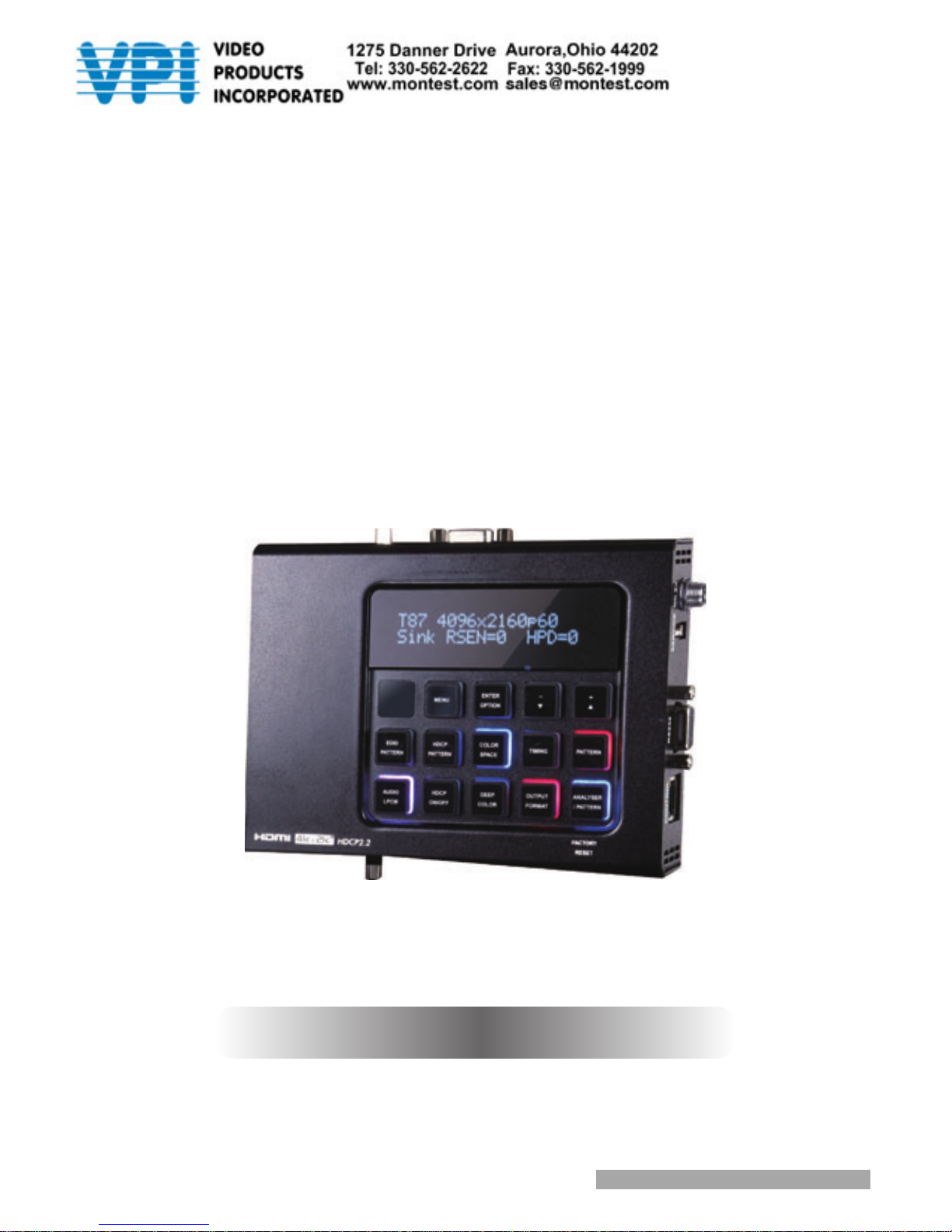
4K HDMI Video Test Pattern Generator
Operation Manual
Operation Manual
Page 2

Page 3

DISCLAIMERS
The information in this manual has been carefully checked and
is believed to be accurate. Video Products Inc (VPI) assumes no
responsibility for any infringements of patents or other rights of third
parties which may result from its use.
Video Products Inc assumes no responsibility for any inaccuracies
that may be contained in this document. VPI also makes no
commitment to update or to keep current the information contained
in this document.
VPI reserves the right to make improvements to this
document and/or product at any time and without notice.
TRADEMARK ACKNOWLEDGMENTS
All products or service names mentioned in this document may be
trademarks of the companies with which they are associated.
Page 4

SAFETY PRECAUTIONS
Please read all instructions before attempting to unpack, install or
operate this equipment and before connecting the power supply.
Please keep the following in mind as you unpack and install this
equipment:
• Always follow basic safety precautions to reduce the risk of re,
electrical shock and injury to persons.
• To prevent re or shock hazard, do not expose the unit to rain,
moisture or install this product near water.
• Never spill liquid of any kind on or into this product.
• Never push an object of any kind into this product through any
openings or empty slots in the unit, as you may damage parts
inside the unit.
• Do not attach the power supply cabling to building surfaces.
• Use only the supplied power supply unit (PSU). Do not use the PSU
if it is damaged.
• Do not allow anything to rest on the power cabling or allow any
weight to be placed upon it or any person walk on it.
• To protect the unit from overheating, do not block any vents or
openings in the unit housing that provide ventilation and allow for
sufcient space for air to circulate around the unit.
Page 5

CONTENTS
1. Introduction ............................................1
2. Applications
...........................................1
3. Package Contents
................................1
4. System Requirements
............................2
5. Features
..................................................2
6. Operation Controls and Functions
.......3
6.1 Front Panel
........................................3
6.2 Top Panel
..........................................7
6.3 Bottom Panel
....................................7
6.4 Left Panel
..........................................8
6.5 Right Panel
........................................8
6.6 Remote Control
................................9
6.7 RS-232 Protocol
...............................10
6.8 RS-232 and Telnet Commands
.....11
6.9 Telnet Control
.................................15
6.10 OSD Menu
.....................................17
6.10 .1 Analyzer Mode
...................17
6.10. 2 Pattern Mode
.....................23
6.11 Test Timings
....................................27
6.11.1 Input Timings
........................27
6.11.2 Output Timings
....................28
6.12 Test Patterns
..................................30
7. Connection Diagram
..........................47
8. Specications
......................................48
8.1 Technical Specications
...............48
8.2 Supported Color Formats
..............49
8.3 Supported Audio Formats
.............49
9. Acronyms
.............................................50
Page 6

1
1. INTRODUCTION
The MONTEST-HD4K Signal Generator & Analyzer is an advanced and handy
tool for generating, testing and verifying the signal path within your 6G
HDMI ecosystem. With 88 built-in resolutions, 55 test patterns and over
a dozen types of A/V analysis functions, this unit provides an enormous
range of testing options. HDMI data packet, EDID and HDCP analysis
is supported along with EDID upload and emulation. Additionally the
Status and Control Data Channel (SCDC) can be monitored, allowing
HDMI 6G signal detection and analysis. Up to 8 channels of LPCM
audio test tones can be generated with a wide range of frequencies.
The unit also supports the ability to upload up to 2 user-generated
graphic les which can be used as additional test patterns. The use of
multi-function and multi-color backlit buttons allows for easy operation
of the unit’s wide variety of functions and a clear OLED display
provides a way to quickly view the current signal status information. In
addition to the front panel buttons, the unit can also be controlled via
RS-232, Telnet and IR providing a complete range of control options.
2. APPLICATIONS
• Installer/Integrator multi-function test tool
• HDMI source and sink testing
• UHD system/SCDC error identication
• Third-party equipment setup
• Source and sink EDID reading, writing and saving
• HDCP compliance verication
• Production testing
• R&D design and testing
3. PACKAGE CONTENTS
• 1×HDMI 6G Signal Generator & Analyzer
• 1×Remote Control
• 1×DC to USB Power Cable
• 1×5V/2.6A Power Adaptor
• 1×Operation Manual
Page 7

2
4. SYSTEM REQUIREMENTS
• HDMI/VGA receiving equipment such as an HDTV, monitor or audio
amplier and/or HDMI source equipment such as a media player,
video game console or set-top box.
• Analog audio source equipment such as a PC or media player
and/or analog audio receiving equipment such as headphones, an
audio amplier or powered speakers.
• RS-232 or Ethernet control device such as PC/Laptop. (Optional)
• USB enabled device for uploading user test patterns.
5. FEATURES
• HDMI 2.0 (up to 4K@60Hz 4:4:4) and DVI 1.0 compliant
• HDCP 1.4 and 2.2 compliant
• Analysis of source and sink data paths up to 6G HDMI signals
• Analysis of HDMI data packets
• Analysis and control of HDCP v1.4 and v2.2
• Analysis and emulation of EDID data, including SCDC
• Analysis of input audio signals
• HDR bypass and analysis support
• Generate HDMI timings up to 6Gbps (4096×2160@60Hz 4:4:4, 8-bit)
• Generate HDMI and VGA signal outputs
• VGA output supports 350p, 480p, 576p, 720p, 1080i, 1080p, 640×480,
800×600, 1024×768, 1280×1024, 1366×768, 1400×1050, 1440×900,
1600×900 (RB), 1600×1200, 1680×1050, 1920×1200 (RB), 2048×1080p
• HDMI output supports 350p, 480p, 576p, 720p, 1080i, 1080p, 640×480,
800×600, 1024×768, 1280×1024, 1366×768, 1400×1050, 1440×900,
1600×900 (RB), 1600×1200, 1680×1050, 1920×1200 (RB), 3G4K, 6G4K
• 2 custom user test pattern resolutions - 640×480 & 1920×1080
• External stereo audio input and output
• Generation of LPCM sinewave audio on up to 8 channels
• Front-panel, RS-232, Telnet, and IR Remote controls
• OLED display with rapid updates of current status information
Page 8
3
• Detailed OSD for settings and informational displays
• Supports USB rmware and pattern update
• Small and portable unit
6. OPERATION CONTROLS AND FUNCTIONS
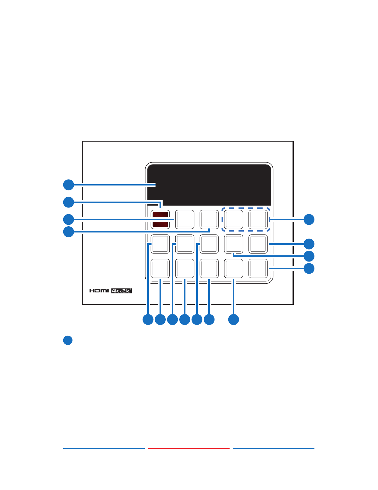
6.1 Front Panel
FACTORY
RESET
MENU
ENTER
OPTION
COLOR
SPACE
TIMING PATTERN
HDCP
PATTERN
EDID
PATTERN
DEEP
COLOR
OUTPUT
FORMAT
ANALYSER
/ PATTERN
HDCP
ON/OFF
AUDIO
LPCM
-
+
HDCP2.2
No Signal
5V=0 CKDT=0 SCDT=0
1
8
5
6
7
4
2
1512
10
1413119
3
1
OLED Screen: Displays the current signal analysis information
or test pattern mode selection details including input and/or
output resolution timing. The screen layout changes completely
depending on the unit’s mode.
Page 9

4
Analyzer Mode (Analyzer/Pattern button is RED): In Analyzer mode,
if there is no live video source detected on the input port, the
OLED will display any voltage, TMDS or sync that might be present.
Once a live video signal is detected, the unit will display that
signal’s current timing, format, HDCP version, AV Mute status, color
space, color depth and audio format.
No Signal
5V=0 CKDT=0 SCDT=0
TMDS clock
detection
+5V pin
detection
Sync signal
detection
1920x1080p24 3D HDMI
HDCP1 M Y444 12B LPCM
Resolution
HDCP
1.4/2.2
Color
depth
Color
space
General control
package
Audio
HDMI/DVI3D
Pattern Mode (Analyzer/Pattern button is BLUE): In Pattern mode,
when the output isn’t connected to a sink, the unit will display the
current output timing, RX Sense, and Hot-plug detection status.
Once an active sink has been connected, the lower portion of the
display will change to indicate the current test pattern number
and name.
T62 1080p59
Sink RSEN=0 HPD=0
Hot plug
detection
RX sense
detection
Sink/
Source
T62 1080p59
P06 Colorbar S.
Test pattern
Test timing
2
IR Window: Accepts IR signals from the included IR remote for
control of this unit only.
3
MENU: Press to enter the OSD menu, or to back out from menu
items.
4
ENTER/OPTION: Press to conrm a selection or to go deeper into a
menu item. When the selected function has optional selections,
Page 10

5
the associated button’s LED will illuminate along with the ▼/▲ (-/+)
buttons.
5
+/- & ▲/▼: Press to move up and down or adjust selections within
menus. These buttons will illuminate when the selected function
has values that can be adjusted up or down.
6
PATTERN: Within Pattern mode, press to enable selection of the
test pattern used. The ▼/▲ buttons will illuminate and are used
to select the new pattern. The new test pattern will automatically
become active after selecting it and pausing for 2 seconds.
Additional variations (if available) are selected by pressing the
button additional times. Within Analyzer mode, press to turn on/off
a “title-safe/action-safe” overlay.
7
TIMING: Press to enable selection of the output timing and
resolution used. The ▼/▲ buttons will illuminate and are used to
select the new timing. The currently selected timing will be shown
on the OLED display. The new timing will automatically become
active after selecting it and pausing for 2 seconds.
Note: In Analyzer mode, please select the “Bypass” timing if you
do not wish for your source’s output signal to be scaled by the unit
before being sent to the display. The LED will blink Red when the
timing is set to Bypass.
8
ANALYZER/PATTERN: Press to switch the unit between Analyzer
Mode (LED=Red) and Pattern Mode (LED=Blue). When in Analyzer
Mode, press and hold the button for 2 seconds to force an RX
hot-plug. When in Pattern Mode, press and hold the button for
2 seconds to turn on/off the AVMute bit within the output’s GCP
(General Control Packet).
FACTORY RESET: Press and hold this button while powering the unit
on to perform a factory reset of the unit.
9
EDID PATTERN: Press to enable selection of the EDID to use on the
HDMI input port. The ▼/▲ buttons will illuminate and are used to
select the new EDID. The currently selected EDID will be shown on
the OLED display. The new EDID will automatically become active
after selecting it and pausing for 5 seconds.
10
AUDIO LPCM: Within Analyzer mode, press to select which digital
audio source pair (0-3) is routed to the primary stereo channel
(LPCM 2.0 and headphone output) for monitoring. The LED color
indicates the selection (Off=SD0, Red=SD1, Blue=SD2, Purple=SD3).
Page 11

6
Within Pattern mode, press to switch between LPCM 2.0
(LED=Red), 5.1 (LED=Blue) and 7.1 (LED=Purple) channel test tone
output formats. Press and hold this button for 2 seconds to allow
adjustment of the output volume.
11
HDCP PATTERN: Press to enable/disable the OSD display of the
detected HDCP version support and handshaking information
between the sink and source. In Analyzer mode the unit is the
RX, in Pattern mode the unit is the TX. In Pattern mode, if HDCP
handshaking fails, an error message “HDCP OUT FAIL” will be
displayed on the OSD.
12
HDCP ON/OFF: Press to switch between supported HDCP versions
or to disable HDCP. Within Analyzer mode, OFF (LED=Off), HDCP 1.4
(LED=Red), and HDCP 1.4+2.2 (LED=Blue) modes are available for
the input port. Within Pattern mode, OFF, HDCP 1.4, and HDCP 2.2
modes are available for the output port.
13
COLOR SPACE: Press repeatedly to switch between the available
color space formats. The button’s LED is colored to indicate the
current color space: Red=RGB, Blue=YCbCr 4:4:4, Purple=YCbCr
4:2:0, Off=YCbCr 4:2:2.
14
DEEP COLOR: Press repeatedly to switch between the available
output color bit depth options. The button’s LED is colored to
indicate the current bit depth: Off=8-bit, Red=10-bit, Blue=12-bit.
15
OUTPUT FORMAT: Press to switch between DVI (LED=Blue) and HDMI
(LED=Red) output formats. Press and hold the button for 2 seconds
to disable/enable video output completely. The button’s LED will
turn off when output is disabled.
Page 12

7
6.2 Top Panel
VGA OUT
HDMI OUT
AUDIO OUT
321
1
AUDIO OUT: Connect to powered speakers or an amplier for
stereo analog audio output with a 3.5mm phone jack cable.
2
VGA OUT: Connect to a VGA (RGB) monitor or display for analog
video output.
3
HDMI OUT: Connect to HDMI TVs, monitors or ampliers for digital
video and audio output.
6.3 Bottom Panel
HDMI IN
AUDIO IN
1 2
1
HDMI IN: Connect to HDMI source equipment such as a media
player, game console or set-top box.
2
AUDIO IN: Connect to the stereo analog output of a device such
as a CD player or PC.
Page 13
8
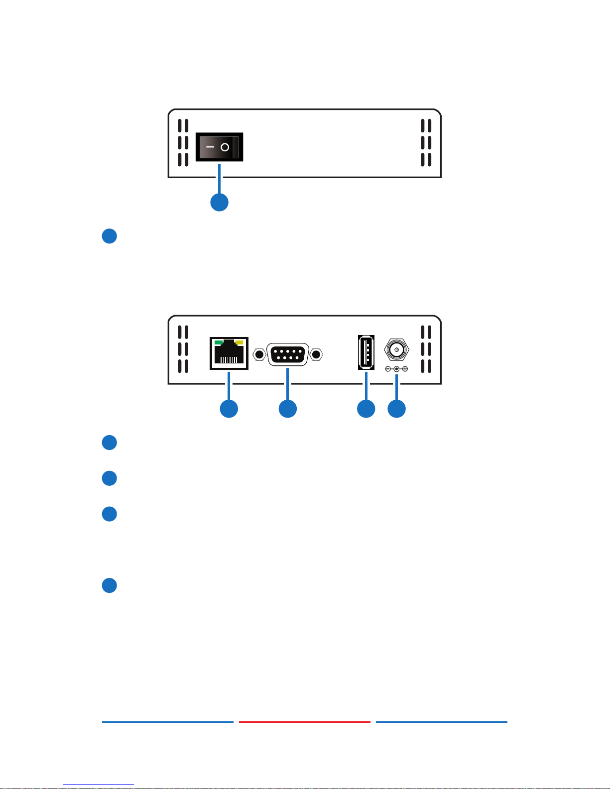
6.4 Left Panel
POWER
1
1
POWER: Flip this switch to turn the unit ON or OFF after connecting
an appropriate power source.
6.5 Right Panel
CONTROLRS232 SERVICE
DC 5V
1 2 3 4
1
CONTROL: Connect directly, or through a network switch, to your
PC/laptop to control the unit via Telnet.
2
RS-232: Connect directly to your PC/laptop to send RS-232
commands to control the unit.
3
SERVICE: This slot is used for rmware updates and uploading
customer designed test pattern les.
Note: The patterns are restricted to 640×480 and 1920×1080. Both
must be 24-bit RGB bitmap les
4
DC 5V: Plug the 5V DC power supply into the unit and connect it to
an AC wall outlet for power or use the DC to USB adapter cable to
connect to a portable USB power bank (2.1A minimum) for power.
Page 14
9
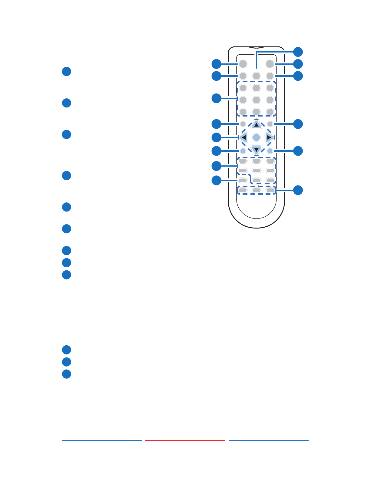
6.6 Remote Control
1
Analyzer/Pattern: Press to switch
between Analyzer Mode and Pattern
Mode.
2
EDID: Press repeatedly to switch
between the available EDIDs for the
HDMI input.
3
Color Space: Press repeatedly to
switch between the available color
space formats (RGB, YCbCr 4:4:4,
YCbCr 4:2:2 and YCbCr 4:2:0).
4
HDCP SW.: Press to switch between
supported HDCP versions or to
disable HDCP.
5
Format: Press to switch between DVI
and HDMI output formats.
6
VGA~4K6G: Press to directly select
the output resolution.
7
Output On: Press to enable video output.
8
Output Off: Press to disable video output.
9
T-/T+: Press (+/-) to select a new output resolution timing. Within the
OSD menu, press to adjust selections.
P+/P-: Press (+/-) to change the current test pattern. Within the
OSD menu, press to move up and down.
OK: After selecting a pattern, press and hold for 2 seconds to
switch to alternate variations of the pattern. Within the OSD menu,
press to conrm selections.
10
Menu: Press to enter the OSD menu.
11
Exit: Press to exit the OSD or cancel the selection.
12
Source*: Press to display source signal information on the OSD.
Video T*.: Press to display video analysis details on the OSD.
Audio T*.: Press to display audio analysis details on the OSD.
Packet*: Press to display the HDMI input’s packet analysis info.
Hotplug*: Press to force an RX hot-plug event on the input port.
OK
Output On
Pattern
Analyser/
HDCP SW.
Output Off
Color Space FormatEDID
T+
Menu
P+
Exit
P
-
T
-
Audio CH HotplugPacket
Sink AVMute1 AVMute0
Source Audio T.Video T.
VGAWXGA WUXGA
480p 720p 1080p
1080i4K3G 4K6G
Vol+Vol-Mute
1
2
7
6
9
10
12
13
4
5
3
8
11
14
Page 15

10
Sink**: Press to display HDMI output detection/information on the
OSD.
AV Mute1**: Press to turn on the AVMute bit within the output’s
GCP.
AV Mute0**: Press to turn off the AVMute bit within the output’s
GCP.
Note: * for use in Analyzer Mode only;
Note: ** for use in Pattern Mode only.
13
Audio CH: Within Analyzer mode, press to select which digital
audio source pair (0-3) is routed to the primary stereo channel for
monitoring. Within Pattern mode, press to switch between LPCM 2.0,
5.1 and 7.1 channel test tone output formats.
14
Mute/Vol-/Vol+: Press the Mute button to mute both digital and
analog audio outputs. Press the Vol-/Vol+ buttons to increase/
decrease the volume.
6.7 RS-232 Protocol
SIGNAL GENERATOR
►
◄
REMOTE CONTROLLER
Pin Assignment Pin Assignment
1 NC 1 NC
2 TxD 2 RxD
3 RxD 3 TxD
4 NC 4 NC
5 GND 5 GND
6 NC 6 NC
7 NC 7 NC
8 NC 8 NC
9 NC 9 NC
Baud Rate: 115200bps
Data Bits: 8
Parity: None
Flow Control: None
Stop Bit: 1
Page 16

11
6.8 RS-232 and Telnet Commands
COMMAND DESCRIPTION
$boot go Reboot the unit.
During the boot process the unit
won’t respond to commands.
$boot? Display the boot status.
$edid_copy_sink [c1~c10] Copy the HDMI sink’s EDID to a
copy slot (C1~C10). (If the copy
fails “err” will be displayed)
$edid_read [d1~d10/c1~c10/
sink],block[0/1]
Displays the selected data block
from the selected EDID slot.
The data is output as a bitstream
of 128 bytes following the
CR+LF within the response. (Not
supported over Telnet)
$edid_rx [d1~d10/c1~c10/sink] Select the EDID to use on the
unit’s HDMI input.
$edid_rx? Display the current RX EDID
selection.
$edid_write
[c1~c10],block[0/1]<CR><LF>
[128 byte data]
Directly write an EDID block to
one of the copy slots (C1~C10).
The data must be sent as a
bitstream of 128 bytes following
the CR+LF in the command.
$factory Perform a factory reset & restart
the unit.
$fwver? Display the current rmware
version.
$hdcp_in_sw [off/on] Turn HDCP on/off on the input
port. (Analyzer mode only)
Page 17

12
COMMAND DESCRIPTION
$hdcp_in_sw? Display the HDCP on/off setting
for the input port.
$hdcp_in_detect? Detect the HDCP status of the
source.
$hdcp_in_ver [v1.4/v1.4+v2.2] Set the HDCP version to use on
the input port. (Analyzer mode
only)
$hdcp_in_ver? Display the current HDCP version
on the input port.
$hdcp_out_sw [off/on] Turn HDCP on/off on the output
port. (Pattern mode only)
$hdcp_out_sw? Get the HDCP output
communication status.
A status of "Talk" means
it's currently performing
handshaking.
$hdcp_out_ver [v1.4/v2.2] Set the HDCP version to use on
the output port. (Pattern mode
only)
$hdcp_out_ver? Display the current HDCP version
on the output port.
$help Show command list.
$? Show command list.
$model? Display model number.
$motion_text [text] Set text for Motion-H and
Motion-V patterns. The maximum
length of the text is 20 characters.
$motion_text? Display the text used for the
Motion-H and Motion-V patterns.
$net_gate? Display the gateway address.
Page 18

13
COMMAND DESCRIPTION
$net_ip? Display the IP address.
$net_ip_mode [dhcp/static] Set the IP mode.
$net_ip_mode? Display the IP mode status.
$net_link? Display the Ethernet link status.
$net_mac? Display the Ethernet MAC
address.
$net_mask? Display the netmask address.
$net_static_gate [xxx.xxx.xxx.
xxx]
Set the static gateway address.
$net_static_gate? Display the static gateway
address.
$net_static_ip [xxx.xxx.xxx.xxx] Set the static IP address.
$net_static_ip? Display the static IP address.
$net_static_mask [xxx.xxx.xxx.
xxx]
Set the static netmask address.
$net_static_mask? Display the static netmask
address.
$pattern [1/2/3/~] Select a test pattern to display.
(P01, P02, P03, etc.)
$pattern? Display the current test pattern
selection.
$task_mode [analyser/pattern] Set the unit’s operation mode.
$task_mode? Display the unit’s current
operation mode.
$timing [1/2/3/~] Select the output resolution
timing to use. (T01, T02, T03, etc.)
$timing? Display the unit’s current output
resolution timing selection.
$update_fw Update the rmware from USB &
reboot the unit.
Page 19

14
COMMAND DESCRIPTION
$update_img480 Update the 640×480 image from
USB & reboot the unit.
$update_img1080 Update the 1920×1080 image
from USB & reboot the unit.
Note:
• All commands MUST start with the “$” character or the command
will not be recognized by the unit.
• Commands are not case-sensitive.
• Commands must end with a carriage return (0x0D). Use of a line
feed(0x0A) is optional.
• The characters “[“ and “]”are placed around variable command
parameters where there is a choice of more than one item. Please
type the selected parameter without the “[“ and “]”characters
when entering the command.
• The unit will respond to most commands with a repeat of the original
command followed by the specied parameters or requested
information except where otherwise noted. If an invalid command
is entered the unit will respond with “$err”.
• All unit responses end with a carriage return(0x0D) + line feed(0x0A).
• Only one command may be processed at a time. Do not send
additional commands until the response from the previous
command has been received.
• Some commands are not supported over Telnet.
Page 20

15
6.9 Telnet Control
Before attempting to use telnet control, please ensure that both the
unit and the PC/Laptop are connected to the same active networks.
To access Telnet in Windows 7, click on the “Start” menu and type
“cmd” in the search eld, then press “Enter”.
Under Windows XP go to the “Start” menu, click on “Run”, type “cmd”
then press “Enter”.
Under Mac OS X, go to Go→Applications→Utilities→Terminal
See below for reference.
Once in the CLI (Command Line Interface) type “telnet” followed by
the IP address of the unit and “23”, then hit “Enter”. The IP address can
be found in the OSD within the “Ethernet” menu item.
Page 21

16
This will connect us to the unit we wish to control. Type “$help” or “$?”
to list the available commands.
Note: Commands will not be executed unless followed by a carriage
return. Commands are not case-sensitive. If the IP address is changed
then the IP address required for telnet access will also change
accordingly.
Page 22

17
6.10 OSD Menu
6.10 .1 Analyzer Mode
MAIN MENU SUB MENU ADJUSTMENTS DEFAULT
Source Monitor Analytic Data
Video Timing Analytic Data
Audio Timing Analytic Data
Packet Analytic Data
EDID Analyzer HDMI Sink Analytic Data
VGA Sink Analytic Data
RX EDID Analytic Data
Default & Copied
EDID
[D1]~[D10] Default EDID
Settings & [C1]~[C10]
Copied EDID Settings
EDID Emulator RX EDID Select Copy HDMI Sink [D4] 8B 2D
2CH LPCM
HD
[D1] DVI
[D2] VGA
[D3] 8B 2D 2CH LPCM PC
[D4] 8B 2D 2CH LPCM HD
[D5] 12B 2D 8CH Bits
720p
[D6] 12B 3D 8CH Bits HD
[D7] 12B 2D 8CH Bits
4K6G
[D8] 12B 2D 8CH HBR
4K3G
[D9] 12B 2D 8CH HBR
4K420
[D10] 12B 2D 8CH HBR
4K6G
Page 23

18
MAIN MENU SUB MENU ADJUSTMENTS DEFAULT
EDID Emulator
(Cont.)
RX EDID Select [C1] Copy 01 [D4] 8B 2D
2CH LPCM
HD
[C2] Copy 02
[C3] Copy 03
[C4] Copy 04
[C5] Copy 05
[C6] Copy 06
[C7] Copy 07
[C8] Copy 08
[C9] Copy 09
[C10] Copy 10
Copy HDMI Sink
EDID
[C1]~[C10] Copied EDID
Settings
Copy VGA Sink
EDID
[C1]~[C10] Copied EDID
Settings
Rename Copied
Sink EDID
[C1]~[C10] Copied EDID
Settings
Burn EDID to
HDMI Sink
[D1]~[D10] Default EDID
Settings & [C1]~[C10]
Copied EDID Settings
Burn EDID to VGA
Sink
[D1]~[D10] Default EDID
Settings & [C1]~[C10]
Copied EDID Settings
HDCP Input
Monitor
Analytic Data
SCDC Input
Monitor
Analytic Data
Page 24

19
MAIN MENU SUB MENU ADJUSTMENTS DEFAULT
RX Port Controls Hot Plug Preset Low Toggle
High
Toggle
Hot Plug Toggle
Time
50ms~500ms 100ms
Hot Plug Run
RX Sense On On (PoR)
Off
DDC On On (PoR)
Off
V.Freq/1.001
Detection
On On
Off
HDCP Port On/
Off
On On (PoR)
Off
HDCP Port
Version
v1.4 v1.4+v2.2
v1.4+v2.2
HDCP REAUTH_
REQ Toggle
HDCP Counter
Reset
SCDC Port On On
Off
SCDC CED Ch
Auto Clear
On (Auto clear while
source reads CED)
Off
Off
Output Resolution T01 640x350p85~
T88 Bypass
1080p60
Page 25

20
MAIN MENU SUB MENU ADJUSTMENTS DEFAULT
OSD Settings H Position 0%~100% 10%
V Position 0%~100% 10%
Transparency 0~7 (Solid~Transparent) 4
A Mode Color
(Analyzer Mode)
Red Red
Blue
Gray
P Mode Color
(Pattern Mode)
Red Blue
Blue
Gray
Ethernet IP Mode DHCP DHCP
Static
IP Address a.b.c.d (Static Mode) 192.168.
5.88
Subnet Mask a.b.c.d (Static Mode) 255.255.
255.0
Gateway a.b.c.d (Static Mode) 192.168.
5.254
Setup Firmware Update No No
Yes
Image 640x480
Update
No No
Yes
Image 1920x1080
Update
No No
Yes
[Letter H] Option 2Small Medium
Medium
3D Source Image
Bypass
No No
Yes
Information
Refresh
1 Sec 2 Sec
2 Sec
Manual
Page 26

21
MAIN MENU SUB MENU ADJUSTMENTS DEFAULT
Setup
(Cont.)
IR Controller
Address
0~3 0
Copied EDID
Reset
No No
Yes
Ethernet Reset No No
Yes
Factory Reset No No
Yes
Information Analytic Data
Note:
• SCDC= Status and Control Data Channel
• CED= Character Error Detection
• PoR= Power on Reset (setting is reset when the unit is powered off)
• Image le format: 640×480/1920×1080 (RGB, 24-bit, bitmap)
Page 27

22
Source HDR Ability:
- Parse the HDR Static Metadata data block in the sink's EDID.
- Output 4K60 (4:2:0, 10/12-bit), or 4K30 (4:4:4, 10/12-bit).
- Output DRMI (Dynamic Range & Mastering InfoFrame).
Sink HDR Ability:
- Build an RX EDID that includes the HDR Static Metadata data
block.
- Receive 4k60 (4:2:0, 10/12-bit), or 4K30 (4:4:4, 10/12-bit) signals.
- Receive DRMI and decode the HDR contents.
Unit HDR Ability:
- No support for HDR output in Pattern mode.
- Supports HDR bypass & analysis in Analyzer mode.
- HDR EDID must be copied from an connected sink to the RX EDID
through the EDID Emulator menu in Analyzer mode.
- EDID Analyzer & Packet.DRMI for HDR analysis in Analyzer mode.
EDID Settings:
- The unit has 10 built-in EDIDs and 10 custom EDID slots. Within the
OSD menu’s “EDID Emulator” section, the EDID from the currently
connected sink, a built-in EDID, or a custom EDID may be selected
for use as the unit’s EDID. Programming a custom EDID through
the RS-232 connection is supported.
IR Settings:
- The IR remote uses one out of 4
available address channels for
control of the test pattern generator,
allowing up to 4 to be located in the
same area while being controlled by different remotes. Select “IR
Controller Address” within the “Setup” section of the OSD’s main
menu. Assign an address number (from 0 to 3) that matches the
setting on the remote that is to be used with the unit. The default
factory setting is 0.
- The IR remote’s address can be set using the two DIP switches
located on the back of the remote, inside the battery cover. The
default factory setting is 0 (off, off).
ON
1 2
0
ON
1 2
1
ON
1 2
2
ON
1 2
3
Page 28

23
6.10. 2 Pattern Mode
MAIN MENU SUB MENU ADJUSTMENTS DEFAULT
Sink Monitor Analytic Data
Pattern P01 Border ~
P55 Window
Yellow
Audio Output Source HDMI In Int.
Sinewave
(PoR)
Analog In
Int. Sinewave
Volume 0~80 70
Analog Out CH SD0 L/R SD0 L/R
SD1 L/R
SD2 L/R
SD3 L/R
Sampling Rate 48kHz 48kHz
96kHz
192kHz
Word Length 16 Bits 24 Bits
20 Bits
24 Bits
Channels 2CH 7.1CH
5.1CH
7.1CH
SD0-L Freq. Mute 1000Hz
200Hz~1600Hz
SD0-R Freq. Same as "SD0-L Freq." 1000Hz
SD1-L Freq. Same as "SD0-L Freq." 1000Hz
SD1-R Freq. Same as "SD0-L Freq." 1000Hz
SD2-L Freq. Same as "SD0-L Freq." 1000Hz
SD2-R Freq. Same as "SD0-L Freq." 1000Hz
SD3-L Freq. Same as "SD0-L Freq." 1000Hz
SD3-R Freq. Same as "SD0-L Freq." 1000Hz
Page 29

24
MAIN MENU SUB MENU ADJUSTMENTS DEFAULT
EDID Analyzer Analytic Data
EDID Emulator Analytic Data
HDCP Output
Monitor
Analytic Data
SCDC Output
Monitor
Analytic Data
TX Port Controls +5V Out On/Off Follow TMDS Follow
TMDS
Always
On
HDCP Output
On/Off
On Off (PoR)
Off
HDCP Output
Version
v1.4 v1.4
v2.2
HDCP AKE_Send_
Stored_km()
On Off
Off
HDCP Counter
Reset
SCDC CED
Counter Read
On On
Off (TX doesn't read sink
CH0~3 Error-Counter)
SCDC CED
Always Read
On (TX ignores sink
CED_Update ag)
On
Off
SCDC CED Ch
Auto Clear
On (While sink CED_
Update ag=1, TX auto
clear itself CH0~3 Error-
Counter. And read new
counter from sink)
Off
Off
Output Resolution T01 640x350p85~
T88 Bypass (T88
is available in
Analyzer mode)
1080p60
Page 30

25
MAIN MENU SUB MENU ADJUSTMENTS DEFAULT
OSD Settings H Position 0%~100% 10%
V Position 0%~100% 10%
Transparency 0~7 (Solid ~ Transparent) 4
A Mode Color
(Analyzer Mode)
Red Red
Blue
Gray
P Mode Color
(Pattern Mode)
Red Blue
Blue
Gray
Ethernet IP Mode DHCP DHCP
Static
IP Address a.b.c.d (Static Mode) 192.168.
5.88
Subnet Mask a.b.c.d (Static Mode) 255.255.
255.0
Gateway a.b.c.d (Static Mode) 192.168.
5.254
Setup Firmware Update No No
Yes (CPHD-V4.BIN)
Image 640x480
Update
No No
Yes (IMG_480.BMP)
Image 1920x1080
Update
No No
Yes (IMG_1080.BMP)
[Letter H] Option 2Small Medium
Medium
3D Source Image
Bypass
No No
Yes
Information
Refresh
1 Sec 2 Sec
2 Sec
Manual
Page 31

26
MAIN MENU SUB MENU ADJUSTMENTS DEFAULT
Setup
(Cont.)
IR Controller
Address
0~3 0
Copied EDID
Reset
No No
Yes
Ethernet Reset No No
Yes
Factory Reset No No
Yes
Information Analytic Data
Note:
• SCDC= Status and Control Data Channel
• CED= Character Error Detection
• PoR= Power on Reset (setting is reset when the unit is powered off)
Page 32

27
6.11 Test Timings
6.11.1 Input Timings
Resolutions Vertical Frequency (Hz) HDMI
640×350p 85
640×480p 59, 72, 75, 85
720×400p 70, 85
800×600p 56, 60, 72, 75, 85
848×480p 60
1024×768p 60, 70, 75, 85
1152×864p 70, 75, 85
1280×768p 60 (RB), 60, 75, 85
1280×800p 60 (RB), 60, 75, 85
1280×960p 60, 85
1280×1024p 60, 75, 85
1360×768p 60
1366×768p 60 (RB), 60
1400×1050p 60 (RB), 60
1440×900p 60 (RB), 60
1600×900p 60 (RB)
1600×1200p 60
1680×1050p 60 (RB), 60
1920×1200p 60 (RB)
480i 59, 60
480p 59, 60
576i 50
576p 50
720p 25, 29, 30, 50, 59, 60
1080i 50, 59, 60
Page 33

28
Resolutions Vertical Frequency (Hz) HDMI
1080p 23, 24, 25, 29, 30, 50, 59, 60
2048×1080p 23, 24, 25, 29, 30, 50, 59, 60
3840×2160p 23, 24, 25, 29, 30, 50, 59, 60
4096×2160p 23, 24, 25, 29, 30, 50, 59, 60
6.11.2 Output Timings
Resolutions Vertical Frequency (Hz) HDMI DVI VGA
640×350p 85
640×480p 59, 72, 75, 85
720×400p 70, 85
800×600p 56, 60, 72, 75, 85
848×480p 60
1024×768p 60, 70, 75, 85
1152×864p 75
1280×768p 60 (RB), 60, 75, 85
1280×800p 60 (RB), 60, 75, 85
1280×960p 60, 85
1280×1024p 60, 75, 85
1360×768p 60
1366×768p 60 (RB), 60
1400×1050p 60 (RB), 60
1440×900p 60 (RB), 60
1600×900p 60 (RB)
1600×1200p 60
1680×1050p 60 (RB), 60
1920×1200p 60 (RB)
480i 59, 60
480p 59, 60
Page 34

29
Resolutions Vertical Frequency (Hz) HDMI DVI VGA
576i 50
576p 50
720p 50, 59, 60
1080i 50, 59, 60
1080p 23, 24, 25, 29, 30
50, 59, 60
2048×1080p 23, 24, 25, 29, 30, 50, 59, 60
3840×2160p 23, 24, 25, 29, 30, 50, 59, 60
4096×2160p 23, 24, 25, 29, 30, 50, 59, 60
Note:
• RB=Reduced Blanking
• 87 total resolutions.
• VGA output limitations:
- Only supports RGBHV. (No YUV, RGBS or RGsB support)
- In Analyzer mode: VGA output is turned off.
- In Pattern mode: VGA output has limited resolution support.
- OSD Menu display is not supported.
Page 35

30
6.12 Test Patterns
1. Border
The Border pattern presents 4 equal-sized squares dividing the screen
into 4 quadrants, forming a central white cross, with red, green, blue
and white inner squares. Ideal for testing screen boundary, alignment
and pincushion issues. All lines should be straight, and edge transitions
should be sharp.
2. Checkerboard
8×8 24×24 48×48
The Checkerboard pattern displays a repeating black and white
checkerboard image. This is ideal for checking the alignment and
corner convergence of TVs or monitors. Bandwidth can be checked
by observing the vertical transitions. Transitions from black to white
should be sharp. There are 3 variations: 8×8, 24×24 and 48×48.
3. Circle 1
The Circle 1 pattern provides a single white circle in the middle with a
white cross and a white outer border line. This pattern is designed for
quickly conrming that the geometry of the scene is correct and that
the full source is being displayed, edge to edge.
Page 36

31
4. Circle 4
The Circle 4 pattern provides 4 smaller white circles in each of the 4
corners of the screen. This pattern can help conrm that the display is
maintaining correct geometry at the edges of the screen.
5. Black 6. Blue 7. Cyan 8. Green
9. Magenta 10. Red 11. White 12. Yellow
These patterns are full screen purity tests offering eight different full
eld patterns: Black, Blue, Cyan, Green, Magenta, Red, White, Yellow.
The color patterns should display an even distribution of brightness and
consistent color tone across the screen. The 100% white pattern should
display evenly across the screen and not cause the display’s overall
brightness to lower, or for the image to become instable. The black
pattern will give a good idea of the display’s true minimum brightness
capability and is helpful for setting the viewing room lighting levels.
Page 37

32
13. Colorbar Delay
The Colorbar Delay pattern provides a sequence of standard 100%
color bars with a full set of smaller color squares within each bar. This
test is primarily to detect if any of the color components of the video
signal are delayed/skewed relative to each other. Pay close attention
to the left and right sides of the squares and look for a color shift. This
is a common problem when using extreme-length analog extension
products, or very long analog cables.
14. Colorbar-H
The Colorbar-H pattern is a standard (white, yellow, cyan, green,
magenta, red, blue, black) 100% color bar pattern using horizontal
bars.
15. Colorbar Motion
Slow/Fast Motion
The Colorbar Motion pattern is a standard (white, yellow, cyan, green,
magenta, red, blue, black) 100% color bar pattern using vertical bars
with a grey bar moving horizontally across it. There are 2 variations:
slow and fast motion of the grey bar.
Page 38

33
16. Colorbar S.
The Colorbar S. pattern is a standard SMPTE color bar pattern which
is used for rapid verication of signal color accuracy and for display
setup using the Blue-Only option on your display, if it has one.
17. Colorbar Split
The Colorbar Split pattern is a vertical color bar pattern with the
color bars split in the middle by large black and white sections. All
colors (white, yellow, cyan, green, magenta, red, blue) are at 100%
brightness.
18. Colorbar-V (3 variations)
100% 75% 100% & 75%
The Colorbar-V pattern comes in 3 variations. The rst is a standard
(white, yellow, cyan, green, magenta, red, blue, black) 100% color
bar pattern using vertical bars. The 2nd variation has all bars at 75%
brightness. The 3rd variation is split with the top half being at 100% and
the lower half being at 75% brightness.
Page 39

34
19. Cross Hatch 8 (2 variations)
Normal Inverse
The Cross Hatch 8 pattern is a full eld black & white pattern of
crossing vertical and horizontal lines dividing the screen into 8
sections in each direction. This pattern is primarily used to check for
color convergence and pincushion issues in projectors. There are 2
variations: Normal (white lines, black eld) and Inverse (black lines,
white eld).
20. Cross Hatch 16 (2 variations)
Normal Inverse
The Cross Hatch 16 pattern is a full eld black & white pattern of
crossing vertical and horizontal lines dividing the screen into 16
sections in each direction. This pattern is primarily used to check for
color convergence and pincushion issues in projectors. There are 2
variations: Normal (white lines, black eld) and Inverse (black lines,
white eld).
21. Cross Hatch 32 (2 variations)
Normal Inverse
The Cross Hatch 32 pattern is a full eld black & white pattern of
crossing vertical and horizontal lines dividing the screen into 32
sections in each direction. This pattern is primarily used to check for
color convergence and pincushion issues in projectors. There are 2
variations: Normal (white lines, black eld) and Inverse (black lines,
white eld).
Page 40

35
22. Diagonal 1
The Diagonal 1 pattern is a set of 3 diagonal colored lines (red, white
and blue) within a white square in the middle of the screen. This
pattern is used to check for distortion and alignment issues in the
center of the screen.
23. Diagonal 2
The Diagonal 2 pattern is 2 diagonal lines that travel from the corners
to the exact center of the display. This can be used to check for
alignment and geometry issues, particularly with projectors. The outer
border of the screen also has a white outline to verify that the full
image is being displayed.
24. Dot
The Dot pattern is a full eld black & white pattern with a repeating
pattern of single-pixel (resolutions below 4K) or 4-pixel (at 4K) white
dots surrounded by single pixels of black. This pattern is ideal for testing
the signal path/display for bandwidth issues, interference, cross-talk or
scaling issues.
Page 41

36
25. General (3 variations)
Stop/Slow/Fast
Motion
The General pattern is an all-purpose, multi-pattern test to visually
check for multiple issues simultaneously. It includes color bars, 8-step
greyscale, vertical and horizontal multi-burst, cross hatch, circle and
motion patterns. There are 3 variations: No motion, slow motion and
fast motion.
26. Grayscale 8 (3 variations)
Vert. Bar Vert. L/R Bar Hori. Bar
The Grayscale 8 pattern provides a way to check and adjust the
contrast, brightness and grayscale tracking of your display with 8 bars
progressing from 0% to 100% brightness in even steps. When testing
a display, no color should be visible in any of the bars, and all bars
should be visible and distinct. There are 3 variations: 8 vertical bars,
two sets of 8 vertical bars with the lower set reversed, and 8 horizontal
bars.
27. Grayscale 16 (3 variations)
Vert. Bar Vert. L/R Bar Hori. Bar
The Grayscale 16 pattern provides a way to check and adjust the
contrast, brightness and grayscale tracking of your display with 16
bars progressing from 0% to 100% brightness in even steps. When
testing a display, no color should be visible in any of the bars, and all
bars should be visible and distinct. There are 3 variations: 16 vertical
Page 42

37
bars, two sets of 16 vertical bars with the lower set reversed, and 16
horizontal bars.
28. Grayscale 32 (3 variations)
Vert. Bar Vert. L/R Bar Hori. Bar
The Grayscale 32 pattern provides a way to check and adjust the
contrast, brightness and grayscale tracking of your display with 32
bars progressing from 0% to 100% brightness in even steps. When
testing a display, no color should be visible in any of the bars, and all
bars should be visible and distinct. There are 3 variations: 32 vertical
bars, two sets of 32 vertical bars with the lower set reversed, and 32
horizontal bars.
29. Grayscale 64 (3 variations)
Vert. Bar Vert. L/R Bar Hori. Bar
The Grayscale 64 pattern provides a way to check and adjust the
contrast, brightness and grayscale tracking of your display with 64
bars progressing from 0% to 100% brightness in even steps. When
testing a display, no color should be visible in any of the bars, and all
bars should be visible and distinct. There are 3 variations: 64 vertical
bars, two sets of 64 vertical bars with the lower set reversed, and 64
horizontal bars.
Page 43

38
30. Grayscale 256 (4 variations)
Gray Red Green Blue
The Grayscale 256 pattern provides a way to ne tune the contrast,
brightness and grayscale tracking of your display with a full 265 step
gradient progressing from 0% to 100% brightness. When testing a
display, no color should be visible at any point across the gradient,
and the transition from black to white should appear even and
consistent. There are 3 variations: 256 vertical bars, two sets of 256
vertical bars with the lower set reversed, and 265 horizontal bars.
31. Grayscale 256RGB
The Grayscale 256RGB pattern provides a way to ne tune the
contrast, brightness, grayscale and color tracking of your display with
a four full 265 step gradients (gray, red, green, blue) progressing from
0% to 100% brightness. When testing a display, the transition from dark
to light should appear even and consistent across all 4 sections.
32. Grayscale Adjust (256 variations)
Adjustable from 0
to 256
The Grayscale Adjust pattern provides a full eld of grey with user
adjustable brightness levels for testing display gray purity and signal
response. The brightness can be freely adjusted from 0 to 255 by
pressing the PATTERN button followed by the -/+ buttons. The gray
level number will appear in text on screen while it is in adjusting mode.
Page 44

39
33. Grayscale H
The Grayscale H pattern provides 4 distinct gray elds in an “H”
arrangement for testing luminance transition stability. No color or
interference should be visible at the transitions between sections.
34. Grid
The Grid pattern provides a selection of red, green, blue and white
boxes with 2×2 grids within and above them to test for pixel on pixel
and color offset issues.
35. Image (2 variations)
The Image pattern is a user customizable test pattern that holds two
bitmap images. One image is for use with low output resolutions (below
1920×1080) and the other is for high output resolutions (1920×1080 and
above). The low resolution image is a 640×480 bitmap (RGB, 24-bit)
and the high resolution image is a 1920×1080 bitmap (RGB, 24-bit).
Note: To upload new images into the unit please the new replacement
image on a USB thumb drive with the le named “IMG_480.BMP” or
“IMG_1080.BMP” as appropriate. Plug the USB thumb drive into the
USB port on the unit and navigate to the “Setup” menu. Next, activate
the “Image 640×480 Update” or “Image 1920×1080 Update” menu
item, as appropriate, to copy the new image to the unit.
Page 45

40
36. Letter H (2 variations)
Big/Small H
The Letter H pattern is a screen lled with a series of large capital
“H” characters moving vertically up the screen. This is a basic test to
conrm motion detail. There are 2 variations: Large “H” characters
and small “H” characters.
37. Line On/Off-H
The Line On/Off-H pattern generates an alternating pattern of single-
pixel horizontal white lines. This pattern can be used to analyze the
vertical pixel resolution of your display. If the output appears to have
mosaic patterns, or appears to be a solid gray eld, then it is possible
that your display does not fully support the resolution you are currently
sending to it.
38. Line On/Off-V (2 variations)
White & Black Lines Red & Green Lines
(Not supported in
4K)
The Line On/Off-V pattern generates an alternating pattern of single-
pixel vertical lines. This pattern can be used to analyze the horizontal
pixel resolution of your display. If the output appears to have mosaic
patterns, or appears to be a solid gray eld, then it is possible that
your display does not fully support the resolution you are currently
sending to it. There are 2 variations: alternating white & black lines and
alternating red and green lines.
Page 46

41
Note: The red and green variation is not available if the selected
output resolution is 4K. The following timings use dual-pixel lines:
3840×2160@50/60Hz & 4096×2160@25/30/50/60Hz.
39. Motion-H (4 variations)
Slow/Fast RGB Block Slow/Fast String
The Motion-H patterns are a collection of horizontal motion tests. These
can be used to test your display’s pixel on/off response time. There are
4 variations: Slow red/green/blue block, fast red/green/block, slow
moving sample text, fast moving sample text.
Note: The contents of the text can be modied using an RS-232 or
telnet command and can be up to 20 characters long.
40. Motion-V (4 variations)
Slow/Fast RGB Block Slow/Fast String
The Motion-V patterns are a collection of vertical motion tests. These
can be used to test your display’s pixel on/off response time. There are
4 variations: Slow red/green/blue block, fast red/green/block, slow
moving sample text, fast moving sample text.
Note: The contents of the text can be modied using an RS-232 or
telnet command and can be up to 20 characters long.
Page 47

42
41. Multiburst (3 variations)
Stop Motion Slow/Fast Motion
The Multiburst pattern provides a standard multiburst pattern consisting
of vertical white lines that decrease in thickness from left to right
allowing the user to analyze the bandwidth and frequency response
of the video path and connected display. There are 3 variations:
Standard multiburst, multiburst with a slow moving gray block, and
multiburst with a fast moving gray block.
42. Needles
The Needles pattern is a standard needle pulse test. The top half of
the screen is black and the bottom half is white with 2 thin inversebrightness lines crossing from top to bottom. This pattern allows for
analysis of the sharpness, blooming and screen distortion issues that a
display might have.
43. Overscan
The Overscan pattern provides a quick way to determine how much
overscan, or clipping, is being caused by a display. It consists of 5
concentric rectangles moving in from the outer edge of the signal.
They are positioned at 0%, 2.5%, 5%, 7.5% and 10% of the screen size.
Page 48

43
44. Pluge (2 variations)
Full/Limited RGB
Range
The Pluge pattern is used to perform the accurate and consistent
brightness and contrast conguration of a display. Typically you will
want to adjust the brightness control of the monitor so that the rst bar
is just barely indistinguishable from the background black while the
second bar is still clearly visible. Next you should adjust the contrast
so that all four segments of the greyscale box are clearly visible and
distinguishable. There are 2 variations: Full RGB range (0 - 255) and
Limited RGB range (16-235).
45. Square H8 (2 variations)
Normal Inverse
The Square H8 pattern is a full eld black & white pattern of squares
dividing the screen horizontally into 8 sections. This pattern is primarily
used to check projector linearity. There are 2 variations: Normal (white
lines, black eld) and Inverse (black lines, white eld).
46. Square H16 (2 variations)
Normal Inverse
The Square H16 pattern is a full eld black & white pattern of squares
dividing the screen horizontally into 16 sections. This pattern is primarily
used to check projector linearity. There are 2 variations: Normal (white
lines, black eld) and Inverse (black lines, white eld).
Page 49

44
47. Square H32 (2 variations)
Normal Inverse
The Square H32 pattern is a full eld black & white pattern of squares
dividing the screen horizontally into 32 sections. This pattern is primarily
used to check projector linearity. There are 2 variations: Normal (white
lines, black eld) and Inverse (black lines, white eld).
48. Text (4 variations)
Normal & Small Inverse & Small Normal & Big Inverse & Big
The Text pattern is used to check the clarity of text at various sizes and
colors. This is primarily a test for projectors. There are 4 variations: Small
multi-color text on a black background, small multi-color text on a
white background, large multi-color text on a black background, and
large multi-color text on a white background.
Page 50

45
49. Window Blue (4 variations)
Normal 75% Inverse 75% Normal 50% Inverse 50%
50. Window Cyan (4 variations)
Normal 75% Inverse 75% Normal 50% Inverse 50%
51. Window Green (4 variations)
Normal 75% Inverse 75% Normal 50% Inverse 50%
52. Window Magenta (4 variations)
Normal 75% Inverse 75% Normal 50% Inverse 50%
53. Window Red (4 variations)
Normal 75% Inverse 75% Normal 50% Inverse 50%
Page 51

46
54. Window White (4 variations)
Normal 75% Inverse 75% Normal 50% Inverse 50%
55. Window Yellow (4 variations)
Normal 75% Inverse 75% Normal 50% Inverse 50%
These Window patterns are additional screen purity tests offering
seven different patterns with different sized windows of each color
on a black eld: Blue, Cyan, Green, Magenta, Red, White, Yellow. The
color patterns should display an even distribution of brightness and
consistent color tone across the screen. Each pattern has 4 variations:
Normal 75% Window, Inverse 75% Window, Normal 50% Window, and
Inverse 50% Window.
Page 52

47
7. CONNECTION DIAGRAM
FACTORY
RESET
MENU
ENTER
OPTION
COLOR
SPACE
TIMING PATTERN
HDCP
PATTERN
EDID
PATTERN
DEEP
COLOR
OUTPUT
FORMAT
ANALYSER
/ PATTERN
HDCP
ON/OFF
AUDIO
LPCM
-
+
HDCP2.2
VGA OUT
HDMI OUT
AUDIO OUT
HDMI IN
AUDIO IN
POWER
CONTROLRS232 SERVICE
DC 5V
HDMI Source Device
HeadphonesMonitor
4K TV/Display
RS-232 Equipped
PC/Laptop
Internet
Connected
Router
Power
Supply
RS-232LAN
HDMI Input
HDMI Output VGA Output
Analog Audio
Input
Analog Audio
Output
Page 53

48
8. SPECIFICATIONS
8.1 Technical Specications
Video Bandwidth 600 MHz/18Gbps
Input Ports 1×HDMI, 1×3.5mm Stereo, 1×RS-232 (DB-9),
1×IP Control (RJ-45), 1×Service (USB)
Output Ports 1×HDMI, 1×VGA, 1×3.5mm Stereo
Power Supply 5V/2.6A DC (US/EU standards, CE/FCC/UL
certied)
DC to USB Power Source
(Optional)
2.1A (Minimum)
ESD Protection Human body model:
±8 kV (air-gap discharge)
±4 kV (contact discharge)
Dimensions 120mm×30mm×155mm (W×H×D)
[Case Only]
125mm×30mm×162mm (W×H×D)
[All Inclusive]
Weight 796g
Chassis Material Metal
Color Black
Operating Temperature 0˚C~40˚C/32˚F~104˚F
Storage Temperature −20˚C~60˚C/−4˚F~140˚F
Relative Humidity 20~90% RH (non-condensing)
Power Consumption 8.4W
Page 54

49
8.2 Supported Color Formats
Output Resolution (Hz)
RGB
YCbCr
4:4:4
YCbCr
4:2:2
YCbCr
4:2:0
8 10 12 8 10 12 8 12 8 10 12
640×350p@85~
2048×1080p@60
3840×2160p@23~30
* *
* *
4096×2160p@23~30
3840×2160p@50~60
* *
* *
4096×2160p@50~60
Note:
= Specied color depth is supported; *= Specied color depth
is supported & TMDS scrambling is active.
8.3 Supported Audio Formats
Audio Source
Sampling
Rate (kHz) Channels
Word Length
(Bits)
SD0~3 L/R
Freq. (Hz)
HDMI Input Bypass Bypass Bypass Bypass
Analog Input 48 2.0 16, 20, 24 Bypass
96 2.0
192 2.0
Internal
Sinewave
48 2.0, 5.1, 7.1 16, 20, 24 Mute, 200,
400~1600
96 2.0, 5.1, 7.1
192 2.0
• 48kHz supports a maximum of 2 channels at 2048×1080p@29/30Hz
resolution.
• 96kHz supports a maximum of 2 channels at 480i, 576i, 480p,
576p, 640×480p@59Hz, 720×400p@70Hz, 1280×768p@60Hz
(RB), 1366×768p@60Hz (RB), 2048×1080p@29/30/59/60Hz,
4096×2160p@29/30Hz resolutions.
• 192kHz is not supported at 1366×768p@60Hz (RB) or
2048×1080p@29/30Hz resolution.
Page 55

50
9. ACRONYMS
ACRONYM COMPLETE TERM
CED Character Error Detection
EDID
Extended Display Identication Data
HDCP High-bandwidth Digital Content Protection
HDMI High-Denition Multimedia Interface
IR Infrared
OLED Organic Light Emitting Diodes
OSD On-Screen Display
PoR Power on Reset
RB Reduced Blanking
SCDC Status and Control Data Channel
Page 56

 Loading...