

VIDEO PLUS AHP-3112S User Manual
AHP-3112S
12x Outdoor PTZ Dome Camera
User Manual
2
Safety Warning
GVI Security, Inc. reserves the right to revise and improve its products. All specifications are subject to change
without notice.
Notice
To work with the PTZ Dome Cameras, any installer or technician must have the following minimum
qualifications:
A basic knowledge of CCTV systems and components
A basic knowledge of electrical wiring and low-voltage electrical hookups
A basic knowledge of network system setting
Have read this manual completely
Copyright
Under copyright laws, the contents of this user manual may not be copied, photocopied, translated,
reproduced or reduced to any electronic medium or machine-readable format, in whole or in part, without
prior written permission of GVI Security, Inc.
Important Information
Before proceeding, please read and observe all instructions and warnings in this manual. Retain this manual
with the original bill of sale for future reference and, if necessary, warranty service. When unpacking your unit,
check for missing or damaged items. If any item is missing, or if damage is evident, DO NOT INSTALL OR
OPERATE THIS PRODUCT. Contact your dealer for assistance.
Regulation
This device complies with part 15 of the FCC Rules. Operation is subject to the following two conditions:
This device may not cause harmful interference
This device must accept any interference received, including interference that may cause undesired operation.
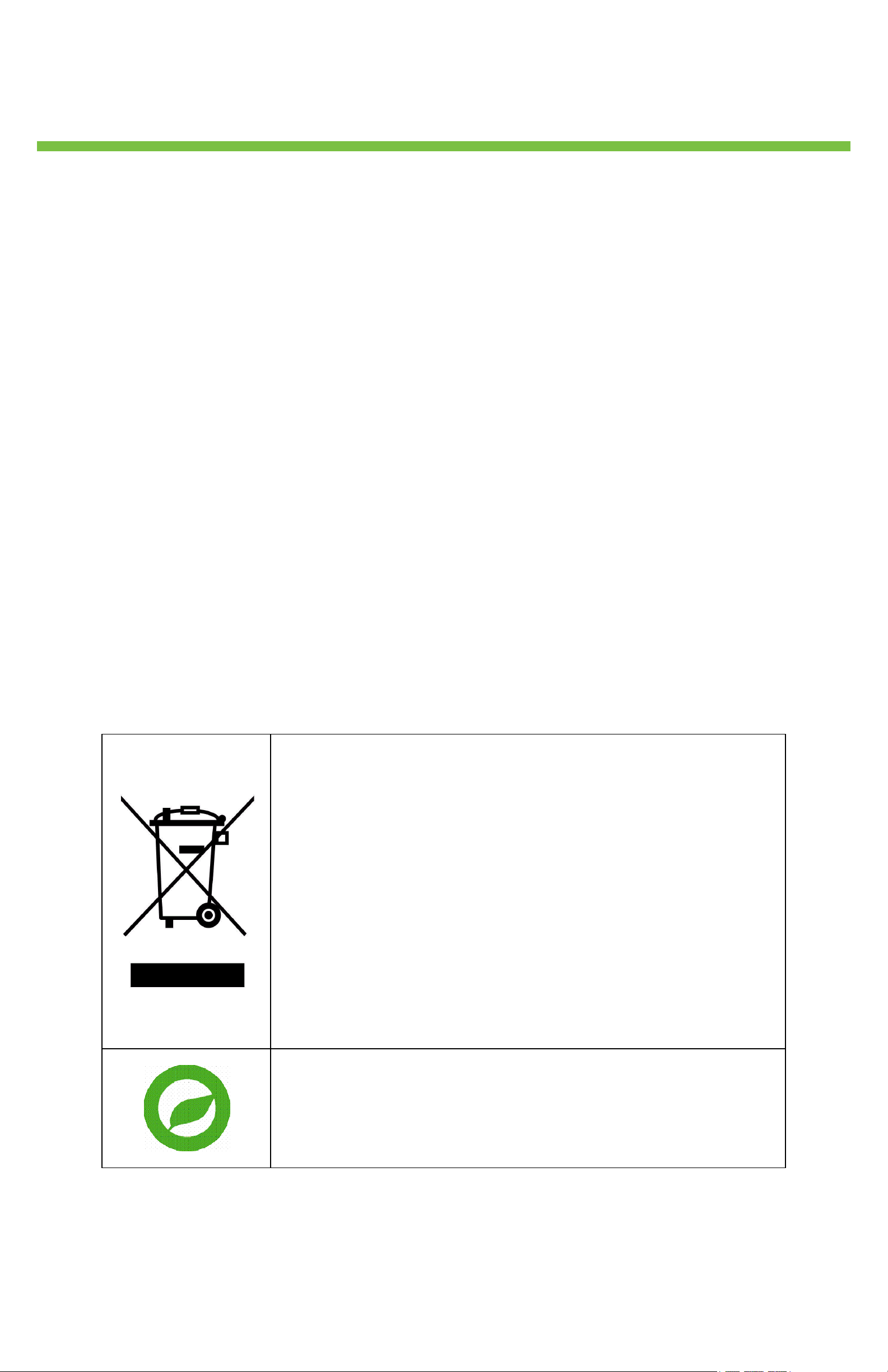
This symbol on the product or on its packaging indicates that this
product shall not be treated as household waste in accordance
with Directive 2002/96/EC. Instead it shall be handed over to the
applicable collection point for the recycling of electrical and
electronic equipment. By proper waste handling of this product
you ensure that it has no negative consequences for the
environment and human health, which could otherwise be caused
if this product is thrown into the garbage bin. The recycling of
materials will help to conserve natural resources.
For more details information about recycling of this product,
please contact your local city office, your household waste
disposal service or the shop where you purchased the product.
Compliance is evidenced by written declaration from our
suppliers, assuring that any potential trace contamination levels of
restricted substances are below the maximum level set by EU
© 2011 GVI Security – v6.24.11
All rights reserved. GVI Security makes no warranty of any kind with regard to this material, including but
not limited to the documentation, function, and performance of these programs and their suitability for any
purpose. This document contains proprietary information, which is protected by copyright. This product
specification and manual is also available in pdf format at www.gviss.com. This information is subject to
change without notice.
Directive 2002/95/EC, or are exempted due to their application.
GVI Security

Safety Information
Retain and follow all safety and operating instructions. Observe all warnings on products. Unplug the product
from the electrical outlet and discontinue use under the following conditions: The power cord or plug is
damaged; the product is exposed to liquid; the product is dropped or an object falls on the product; the
product is noticeably overheated. Please read this manual first for correct installation and operation. Use the
PTZ dome camera under conditions where temperature is between 0°C ~ 40°C (32°F ~ 104°F) and the
outdoor camera under conditions where temperature is between -30°C~45°C (-22°F~113°F), and humidity is
below 90%.
Never install the camera on a ceiling that cannot hold its weight. The product may fall down and cause
damages. Never install the camera near electric or magnetic fields. Install the camera away from TVs, radio
transmitters, magnets, electric motors, transformers, and audio speakers since the magnetic fields distort the
video image. Never install or use the camera in areas exposed to water, oil, or gas. The water, oil, or gas may
3
result in operation failure, electric shock, or fire. Do not use this unit near water (e.g., near a bath tub, wash
bowl, kitchen sink, laundry tub, wet basement, swimming pool, unprotected outdoor installation, or any area
which is classified as a wet location). Never face the camera toward the sun. Direct sunlight may cause fatal
damage to sensors and internal circuits. Touching a wet power cord with hands or touching the power cord
with wet hands may result in electric shock.
Do not service any product yourself. Opening or removing covers that are marked with warning symbols or
labels may expose you to electric shock. Service needed on components inside these compartments should be
done by an authorized service provider. Replace any batteries with the equivalent battery type. Failure to do
so may cause damage or bodily injury. There is a danger of explosion if batteries are incorrectly replaced.
Dispose of all used batteries according to the manufacturer’s instructions. Install the system in an environment
where the ambient temperature does not exceed the maximum rated ambient temperature of the rack mount
system. Ensure there are no obstructions to the case ventilation. Blocking any of the built-in airflow may cause
overheating. The product must be connected to a circuit with an adequate rating to prevent an over-current
condition on the circuit. Slots in the product are provided for ventilation and should never be blocked or
covered since these protect it from overheating. The openings should never be blocked by placing the product
on a flexible surface. The product should not be placed in a built-in apparatus unless the apparatus has been
designed to accommodate the product, proper ventilation is provided for the product, and the product
instructions have been followed.
Operate the product only from the type of power source indicated on the product’s electrical ratings label. If
you have questions about the type of power source to use, contact your authorized service provider. The
power outlet for the power cord should be easily accessible and located as close to the equipment operator
as possible. When you need to disconnect power to the equipment, unplug the power cord from the electrical
outlet. When disconnecting a power cord/cable from an outlet, pull on the connector. Never pull on the cable
itself to disconnect from the power source. Handle all equipment with care when disconnecting from the
product or the power source. Equipment may be hot. The power cord must be properly rated for the
product and for the voltage/current marked on the product’s electrical ratings label. The voltage/current rating
of the cord should be greater than the voltage/current rating marked on the product. Do not overload an
electrical outlet, power strip, or convenience receptacle. Use care when moving products to other countries
with different voltage standards. Substitution for the power supply may result in destruction of the product or
personal injury.
Unplug the product from the wall outlet prior to cleaning. Do not use liquid cleaners or aerosol cleaners. Use
a damp cloth for cleaning. Never insert a foreign object into the product’s openings or ventilation slots. The
product should be placed away from radiators, heat registers, stoves, or other pieces of equipment (including
amplifiers) that produce heat. Allow sufficient air circulation around the product and power supply during use
to ensure adequate cooling of the device. Prevent direct exposure to radiant heat sources. Contact the
provider if replacement parts are required. Use only the parts, upgrades, and options sent from the provider.
GVI Security

Table of Contents
1. OVERVIEW ........................................................................................................................................................................ 5
1.1 Product Features ................................................................................................................................................ 5
1.2 Product Application ........................................................................................................................................... 6
ONNECTING THE PTZ DOME CAMERA ..................................................................................................................... 7
2. C
2.1 Package Content ................................................................................................................................................ 7
2.2 Switch/Connector Definition .......................................................................................................................... 7
2.3 Communication Switch Setting ....................................................................................................................... 8
2.4 ID Setup ................................................................................................................................................................ 9
2.5 Camera Control Protocol Setup .................................................................................................................... 9
2.6 22-Pin Connector Definition ........................................................................................................................... 9
2.7 RS-485 Connector Definition ....................................................................................................................... 11
3. O
PERATION AND CONFIGURATION ............................................................................................................................ 12
4
3.1 OSD Display Format ....................................................................................................................................... 12
3.2 OSD Menu Tree ............................................................................................................................................... 12
3.3 Configuration Menu ......................................................................................................................................... 15
4. A
PPENDIX A: TECHNICAL SPECIFICATION .................................................................................................................... 36
PPENDIX B: SWITCH SETTINGS INDEX TABLE ............................................................................................................ 38
5. A
B.1 Camera ID Setup ............................................................................................................................................. 38
B.2 Protocol Setup .................................................................................................................................................. 46
6. A
PPENDIX C: OSD MENU NOTES .............................................................................................................................. ... 48
7. GVI
SECURITY INFORMATION ....................................................................................................................................... 52
GVI Security

5
I. Overview
The PTZ Dome Camera is an innovative Speed Dome Camera designed for small to medium sized surveillance
applications and possesses true speed dome camera features, such as high speed and accurate Pan/Tilt, up to
144x zoom ratio (12x optical, and 12x digital zoom), 180° Digital Image Flip, Proportional Zoom, and Preset
Speed up to 400°/s. Additionally, it contains 256 Preset Points, 8 Sequence Lines, 4 Auto Pan Lines and 8
Cruise Lines to support automatic operations. It is ideal for all surveillance requirements in hotels, department
stores, intelligent buildings, amusement parks, parking lots, factories, hospitals, schools, stations etc.
The PTZ Dome Camera contains various solutions for low light and high contrast conditions. For example, a
bright background or shade can result in the subject of the image appearing darker. The backlight
compensation function gives a bright and clear image.
The PTZ Dome Camera supports one cabling for easy installation, and can be integrated with various digital
surveillance products, such as DVRs, Control Keyboards and various sorts of accessories for a total
surveillance solution. The camera is incorporated with multiple protocols: Pelco, VCL, Philips, Samsung, etc. to
enhance powerful connectivity.
1.1 Product Features
Precise and Accurate Dome Camera Performance
High Resolution 650 TV lines
Preset Speed up to 400°/sec
Preset Accuracy of 0.225°
360° Endless Pan
Proportional Pan/Tilt Speed
Preset Positions / Auto-Pan / Sequence / Cruise
Auto-Calibration
Digital / Mechanical Image Flip (180°)
Dynamic Dome Applications
Schedule function
Multiple built-in protocols
Lightweight design for easy installation
Flexible indoor mountings
16 Privacy Masks
Motion Detection
Superior Camera Image Quality
12× Optical Zoom
12× Digital Zoom
Digital Slow Shutter
Backlight Compensation
Auto Focus
Auto White Balance
Auto Gain Control
Auto Iris Control
Auto-Calibration
True Day/Night with IR Cut Filter
Minimum Illumination: 0.1 Lux, 0.01 Lux (B/W)
Shadow Fighter XDR
2D / 3D Noise Reduction
Environmental
Anti-Vandal
IP66 Housing
Heater and Blower
Operating Temperature Range: -22˚F ~ 113˚
F (-30˚C ~ 45˚C)
GVI Security
6
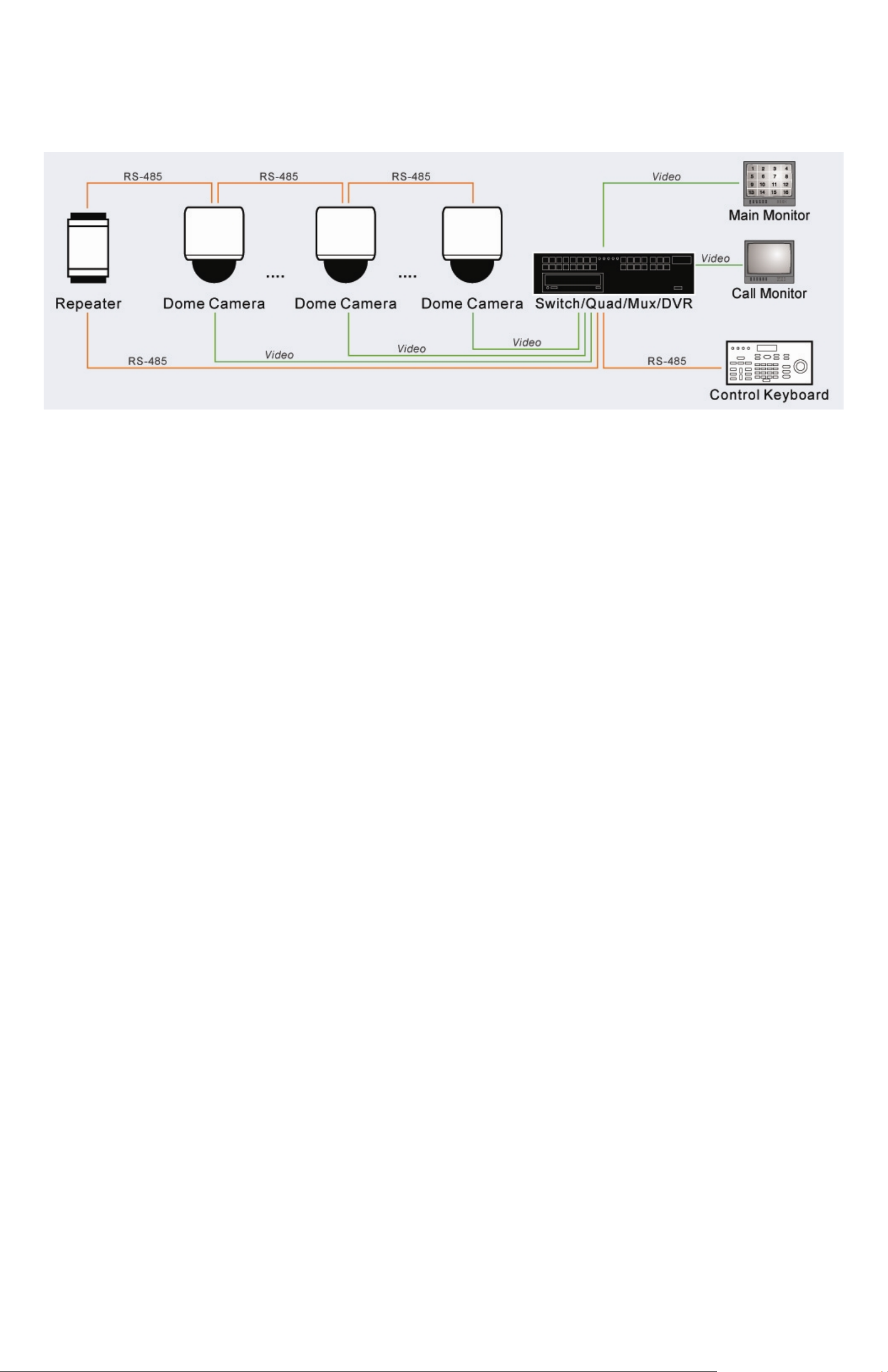
1.2 Product Application
Connect Dome Cameras to other devices, as shown in the diagram, to complete a video surveillance solution.
NOTE: To extend the network distance up to 1.2 km (4000 feet) and to protect the connected devices, it is
highly recommended to use a repeater at the mid-point. However, a repeater may be needed in the network
distance less than 1.2 km if the used cables are not the CAT 5, 24-gauge cables.
GVI Security
7
2. Connecting the PTZ Dome Camera
Please refer to the following sections to connect, set and operate the PTZ Dome Camera. In order to control
the camera, basically a control keyboard or other control device is required.
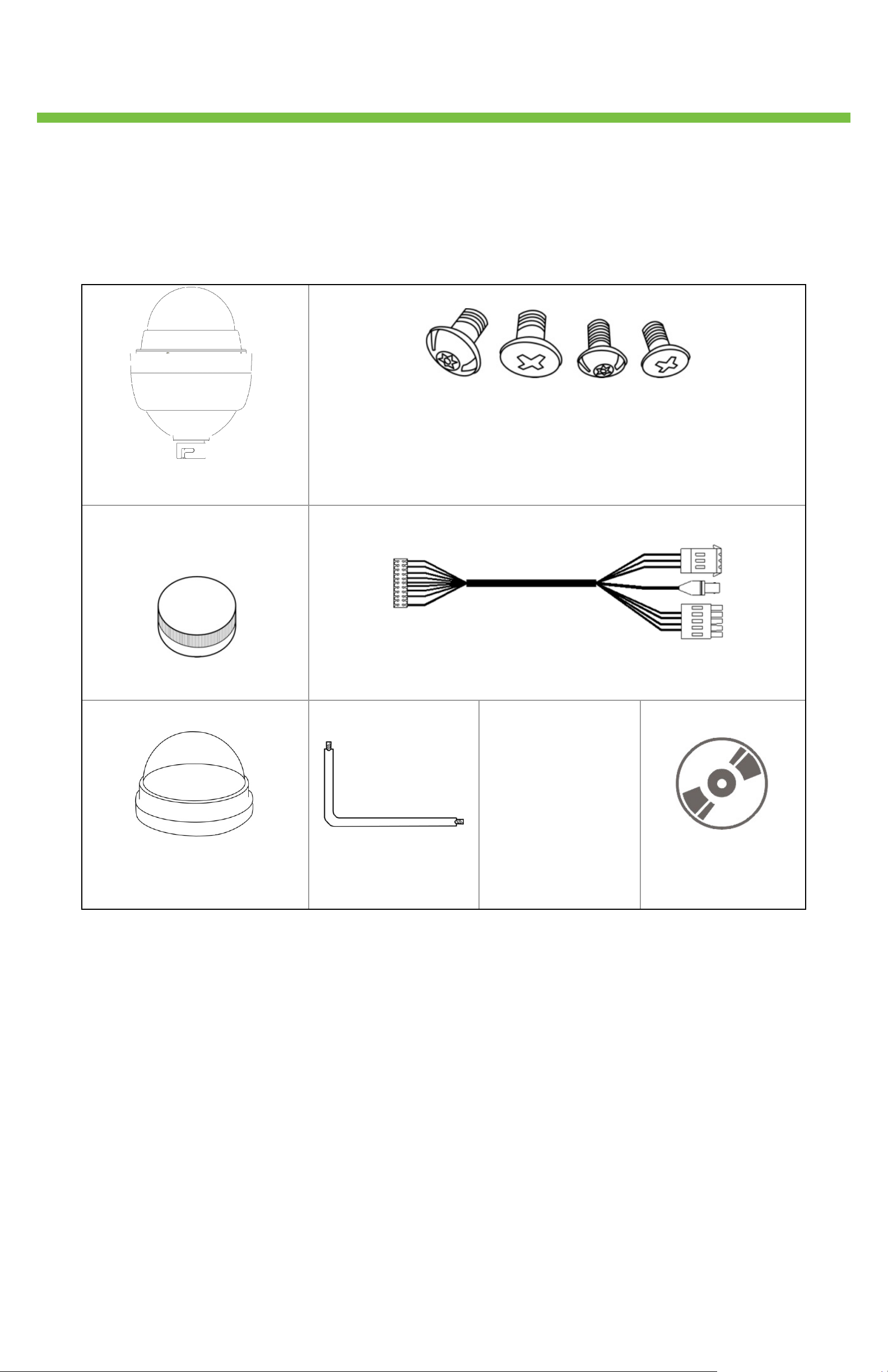
2.1 Package Content
Before proceeding, ensure that the contents match the items listed below. If any item is missing or has defects,
DO NOT install or operate the product and contact the dealer for assistance.
PTZ Dome Camera with
Outdoor Mount Kit
Lubricant
M3 Standard Screw (x1)
M3 Security Screw (x1)
M5 Standard Screw (x1)
M5 Security Screw (x1)
Data Cable for Power Supply, Video Alarm and RS-485 (AC
24V)
Security Torx
Optical Cover
Quick Guide and
User Manual
Product CD
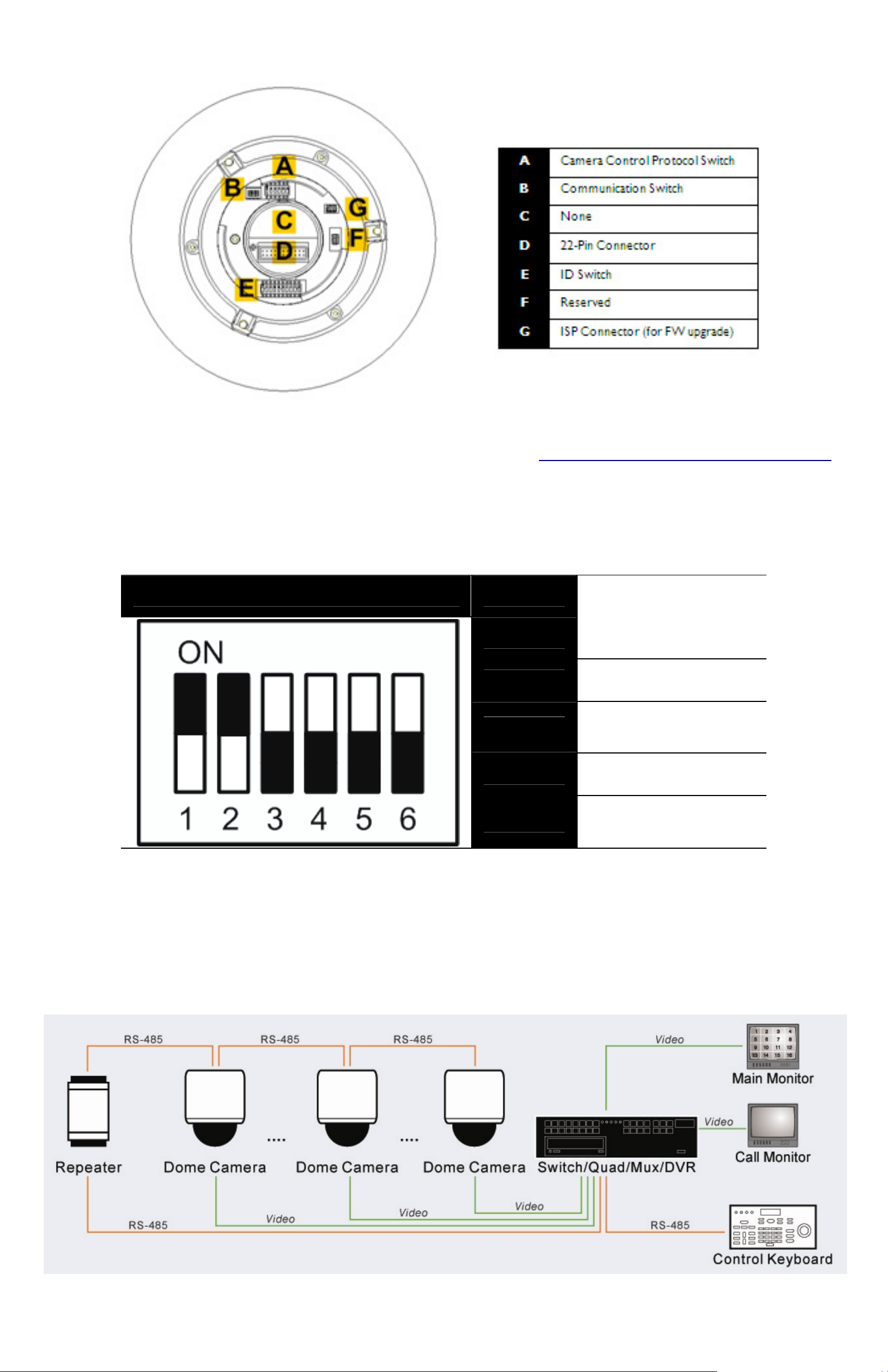
2.2 Description of Camera Parts
Configuring the PTZ Dome Camera’s ID and communication protocol is required before connecting the
camera to other devices. The switches used for configuring these settings are located on the camera’s back
plate. Additionally, the 22-Pin Connector for Data Cable connection and ISP Connector for firmware upgrade
kit connection are also set on the back plate.
Please refer to the diagram and table on the following page for using each switch/connector.
GVI Security
8
The ID and Protocol numbers of the Dome Camera are set with a 10-bit and 6-bit dip switch respectively
using binary system. For switch configuration details, please refer to Appendix B: Switch Settings Index Table
2.3 Communication Switch Setting
The Dome Camera’s communication switches are specified in the table below.
Communication Switch SW 1
RS-485 Setting
SW 2
SW 3 Termination
.
SW 4 Line Lock
SW 5 Factory Default Reset
SW 6 Camera Upgrade
RS-485 is the interface that communicates to the Dome Camera and its control device; for this reason, the
RS-485 setup of the Dome Camera and the control device must be the same. The RS-485 default setting is
half-duplex (see the following diagram). Please do not change the default setting without qualified specialists or
a supplier’s notice. The SW3 and SW4 are used for termination and Line Lock adjustment, respectively. To
use the termination, apply the switch to the last PTZ camera as shown in the figure below. Use the SW5 to
restore the camera to the factory default status. Once firmware upgrade is complete, reset the SW6.
GVI Security
9
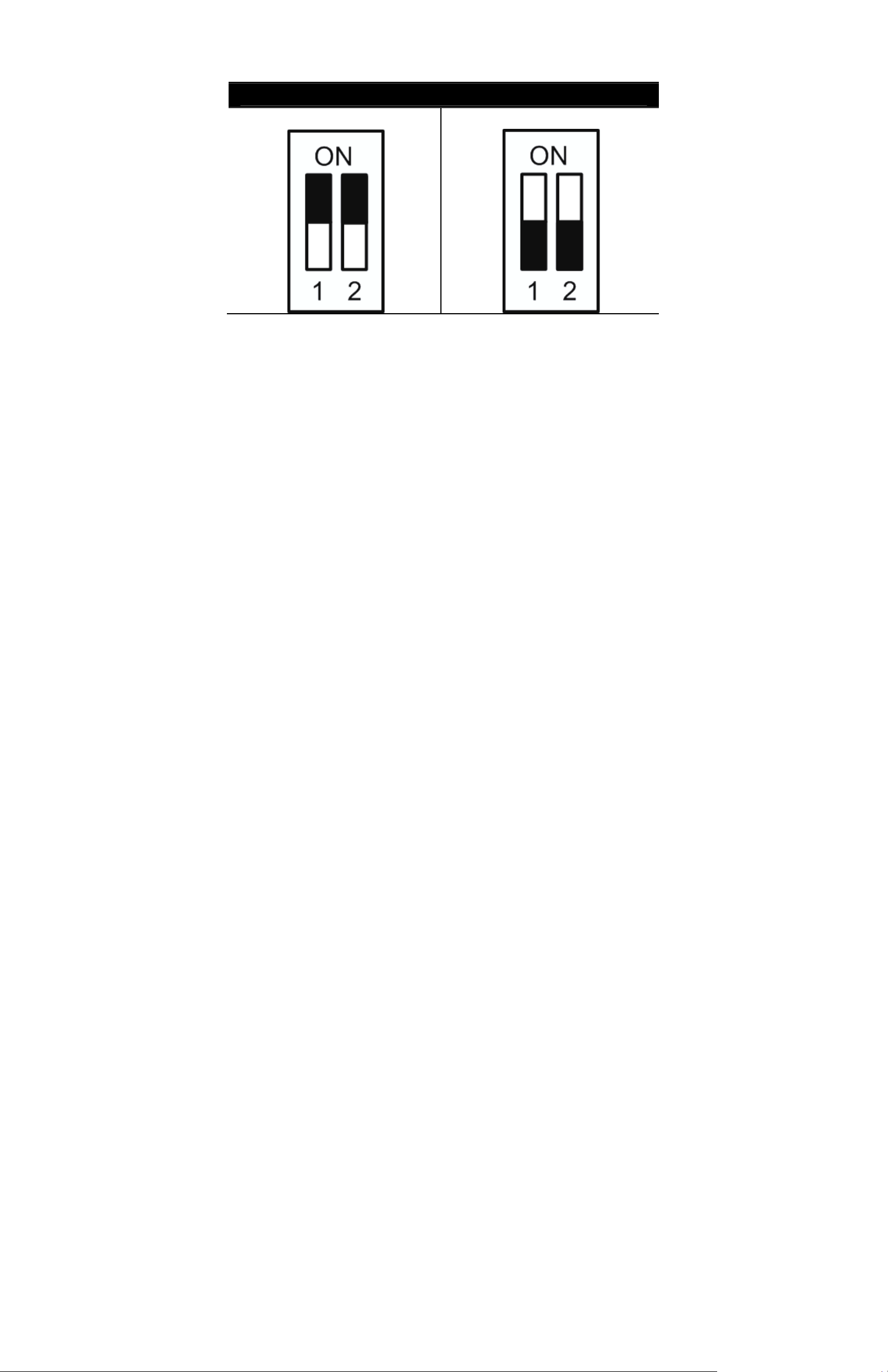
RS-485 Setting
Half-duplex
Full-duplex
The Full-duplex setting leads transmission of data in two directions simultaneously. To complete the setting,
refer to 2.7 RS-485 Connector Definition.
GVI Security
10
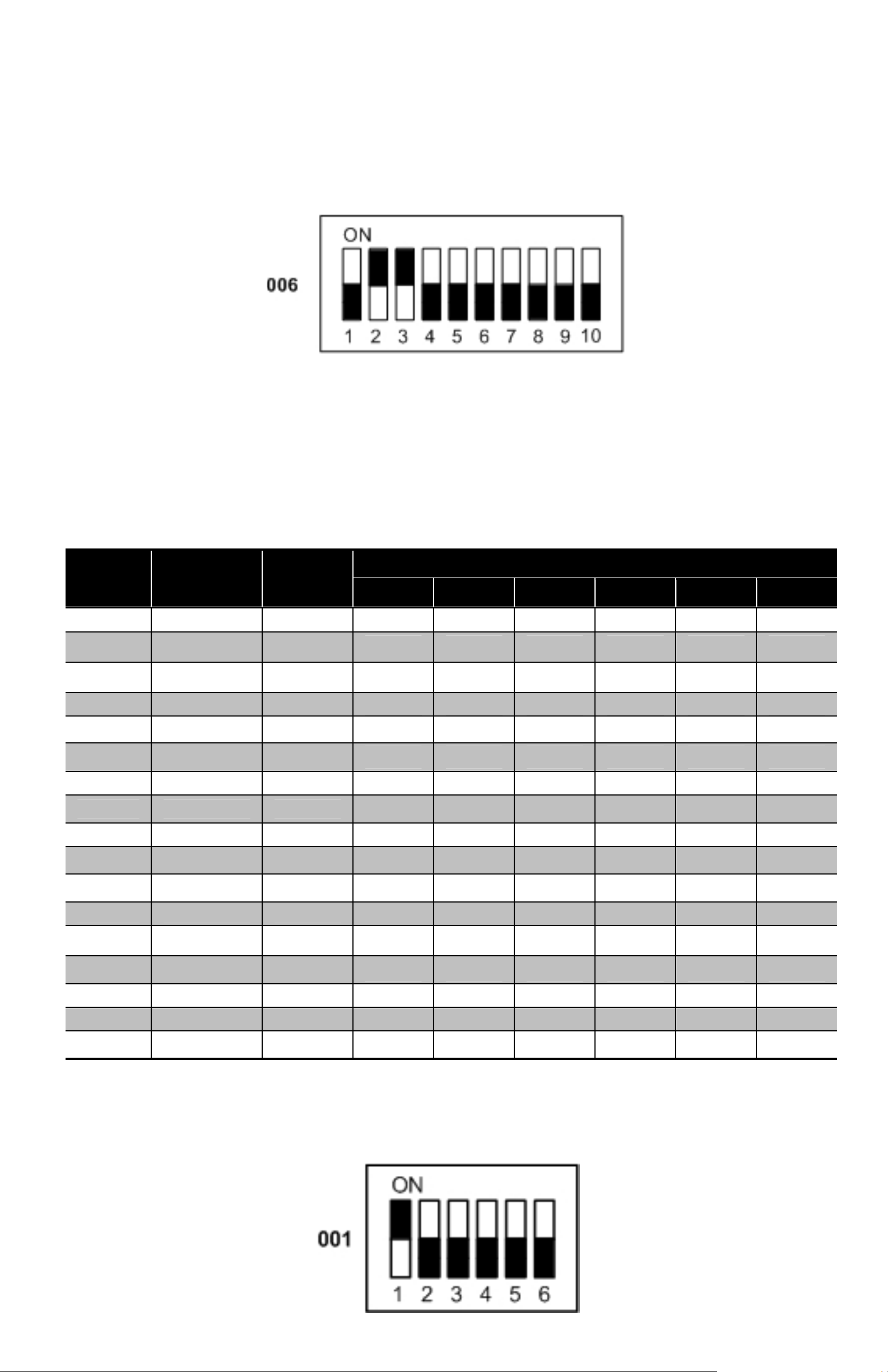
2.4 ID Setup
Change the analog Dome Camera’s ID if there is more than one Dome Camera in the same network. Use the
switch to change the PTZ Dome Camera’s ID by setting the 10-bit dip switch. For instance, if the camera’s ID
is 006, set the SW-2 and SW-3 to “ON,” with the rest to “OFF,” as shown below. For switch configuration
details, refer to Appendix B: Switch Settings Index Table.
NOTE: To prevent communication conflicts, do not give the same ID to two Dome Cameras.
2.5 Camera Control Protocol Setup
Define the protocol based on the devices of the surveillance system. Use one protocol even if the devices are
provided from different manufacturers. Refer to the table below for the supported protocols with their
matching switch numbers and baud rate and choose a protocol for the camera. Refer to Appendix B.2:
Protocol Settings for further configuration details.
Switch
Protocol
No.
00 VCL 9600
01 Pelco D 2400
02 Pelco P 4800
04 Chiper 9600
Baud
Rate
SW-1 SW-2 SW-3 SW-4 SW-5 SW-6
OFF
ON OFF OFF OFF OFF OFF
OFF ON OFF OFF OFF OFF
OFF
OFF
OFF
Switch Setting
OFF
ON
OFF
OFF
OFF
OFF
OFF
OFF
05 Philips 9600
07 VideoPlus 9600
08 AD422 4800
09 DM P 9600
11 Pelco D 4800
12 Pelco D 9600
13 Pelco P 2400
14 Pelco P 9600
15 JVC 9600
21 Kalatel-485 9600
22 Kalatel-422 4800
23 Panasonic 19200
* 31
Samsung 9600
ON OFF ON OFF OFF OFF
ON ON ON OFF OFF OFF
OFF
ON OFF OFF ON OFF OFF
ON
OFF OFF ON ON OFF OFF
ON OFF ON ON OFF OFF
OFF
ON ON ON ON OFF OFF
ON OFF ON OFF ON OFF
OFF
ON
ON ON ON ON ON OFF
OFF
ON
ON
ON
ON
OFF
OFF
ON
ON
ON
ON
ON
ON
OFF
OFF
OFF
OFF
OFF
ON
ON
OFF
OFF
OFF
OFF
OFF
Use the 6-bit dip switch (Camera Control Protocol Switch) to set the camera’s control protocol and its baud
rate. For example, if Pelco D is selected, (switch number one and baud rate 2400) then set the SW-1 to
“ON,” and the rest to “OFF” as shown in the example below.
GVI Security
11
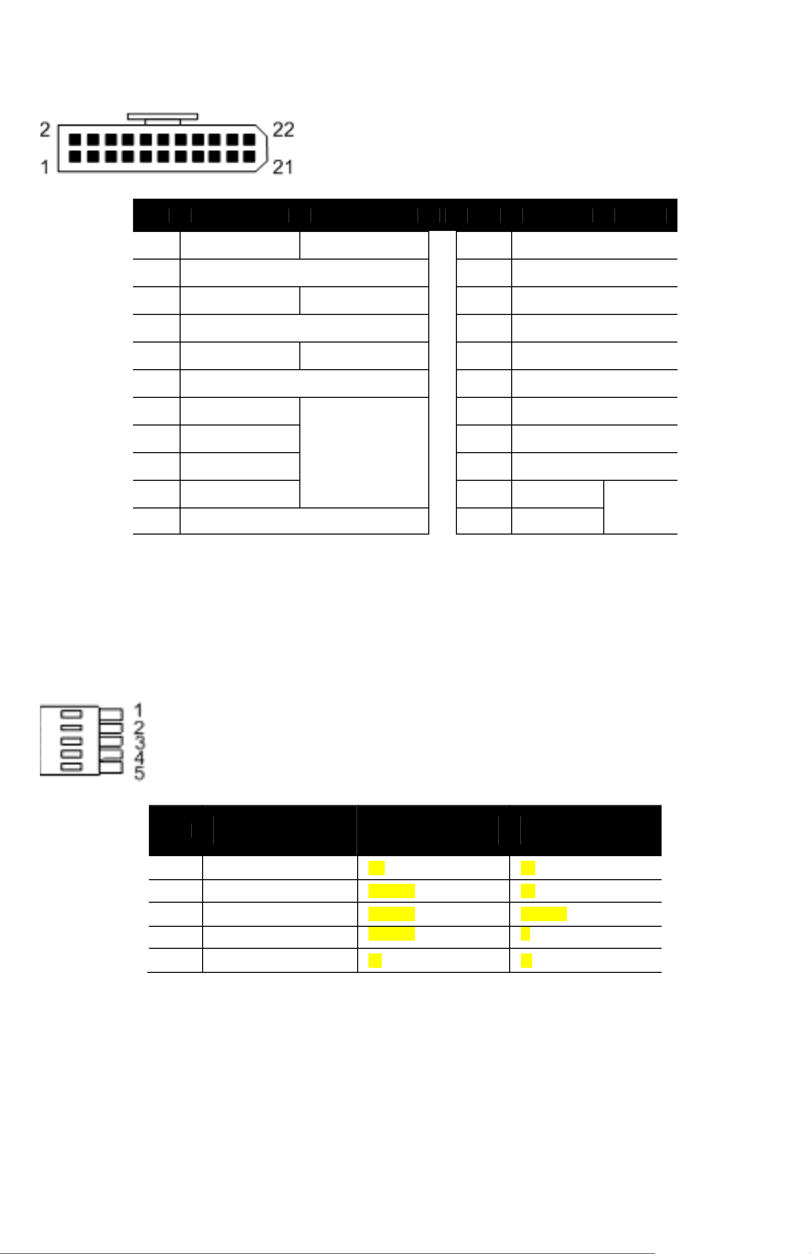
2.6 22-Pin Connector Definition
An AC 24V Data Cable ships with the integrated high speed PTZ Dome for quick installation for demo or
testing usage. See the diagrams below for more information. The Dome Camera’s 22-pin connector definition
is specified in the latter part.
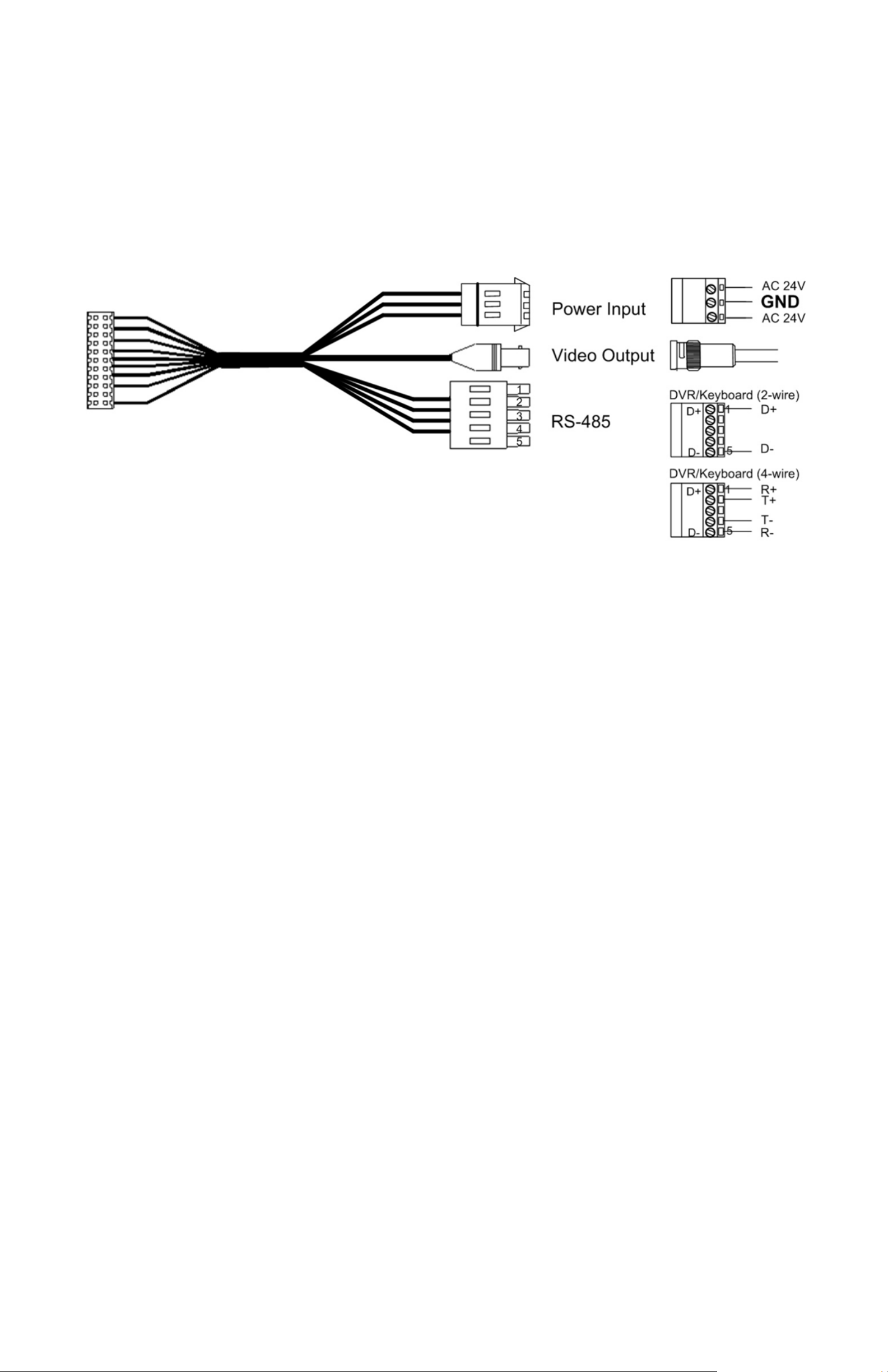
The PTZ Dome Camera’s Data Cables are illustrated as shown below:
AC24V Data Cable:
NOTE: Be careful not to pull the cables improperly during installation. Fasten the cables after completing the
cable connection. When wiring the AC 24V power cable, ensure the Ground wire is inserted into the mid-pin
of the terminal block.
GVI Security
T-
The Dome Camera’s 22-pin connector definition is listed as shown below.
Pin Definition Cable Pin Definition Cable
12
1
2 ALM NC 13 ALM-3
3
4 ALM NO 15 ALM-4
5 FG 20AWG/18AWG 16 ALM-5
6 ALM COM 17 ALM-6
7 T+
8 R- 19 ALM-8
9 T- 20 ALM GND
10 R+ 21 VGND
11 ISOG 22 Video
AC 24-1/DC (+)
AC 24-2/DC (-)
20AWG/18AWG 12 ALM-1
20AWG/18AWG 14 ALM-2
18 ALM-7
24AWG
20AWG
2.7 RS-485 Connector Definition
RS-485 is the interface that communicates the analog PTZ Dome Camera and its control device. Please
connect the control keyboard to the PTZ Dome Camera through the terminal block. The recommended
cables for RS-485 communication are CAT 5 cables; maximum cable length for over 24-gauge wire is 4000
feet (1219 meters). If the total cable length exceeds 4000 feet, using a repeater to maintain the signals is
recommended. Please refer to the figure and table below for pin definition.
Pin
Corresponding Pins
(22-Pin Connector)
Definition
(Half-duplex)
Definition
(Full-duplex)
1
2
3
4 Reserved
5 8,9
7,10 D+ R+
Reserved Reserved T+
Reserved Reserved Reserved
Reserved
D- R-
The factory default setting of connection is Half-duplex. Using Full-duplex requires the adjustment of the data
cable. Unplug and plug the T+/T- connections to the corresponding points.
NOTE: Revise the RS-485 setting prior to restarting the Dome Camera. Refer to 2.3 Communication Switch
Settings for more details.
GVI Security

A A
A
A
A
3. Operation and Configuration
3.1 OSD Display Format
Information shown on the screen is described in terms of OSD display, position, and function description as
shown in the table below.
13
1
2
56
3
4
Posit io n Function OSD Display Description
uto Focus Mode
1 Focus Modes
2 Backlight
M Manual Focus Mode
X
B Back Light Compensation ON
Back Light Compensation OFF
3 Alarm ALARM
4 Zoom Ratio ×1
5 Title
6 Camera ID Show the camera ID
Maximum 20 characters for each title.
16 sets of title are available.
larm Message
Present Zoom Ratio
(Optical Zoom/Digital Zoom)
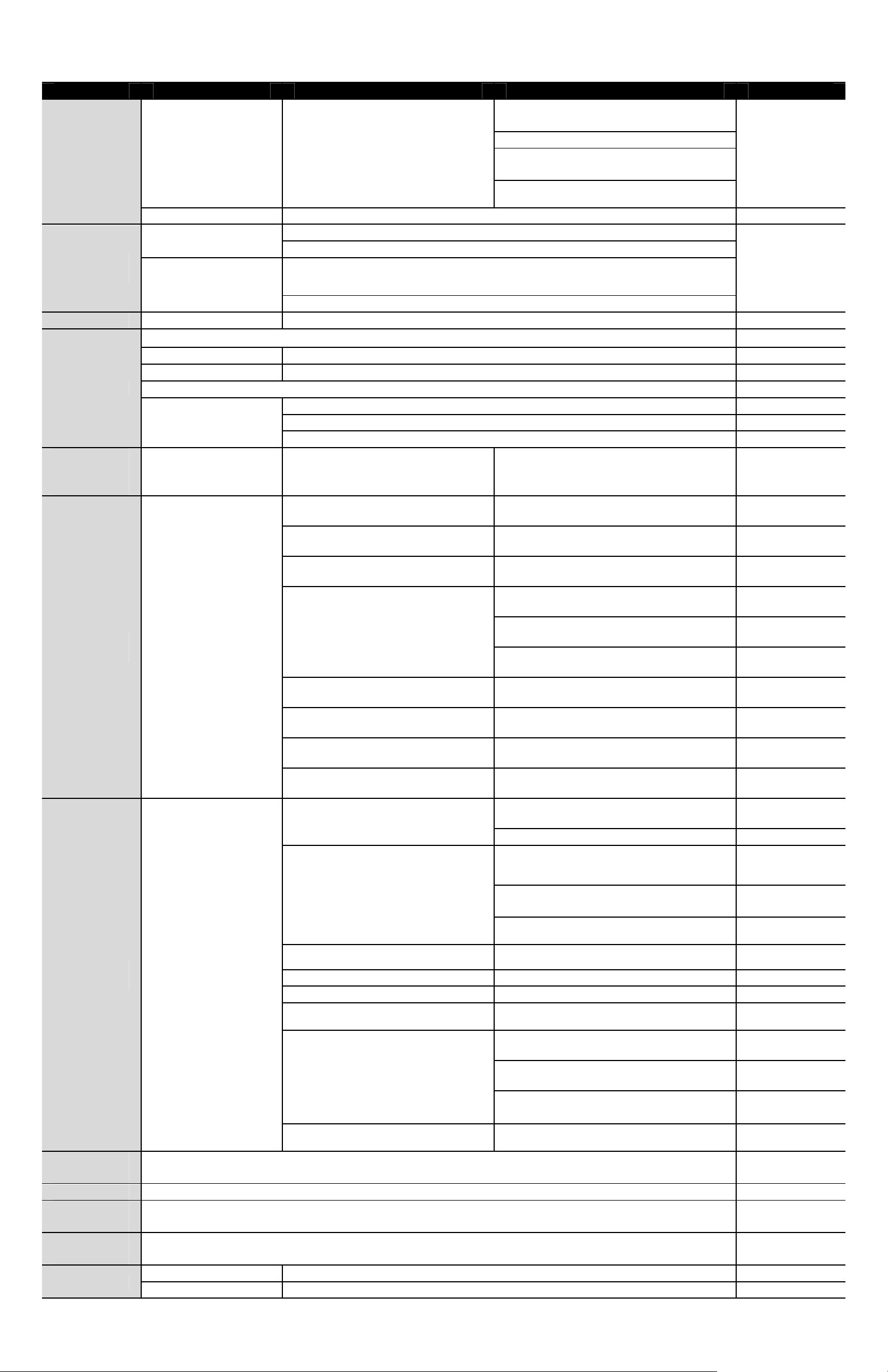
3.2 OSD Menu Tree
The OSD setup menu structure is listed in the following section. The star symbol indicates the factory default.
PTZ Dome Camera Menu Tree
Item Layer 1 Layer 2
F MODE <NORMAL>, <Z. TRIG.>, <PTZ TRIG.>
EXIT + SAVE: YES
FOCUS
<AUTO>
<MANUAL>
Layer 3
Default
UTO
AE MODE
EXPOSURE COMP.
AE MODE
<OFF>, EXPOSURE VALUE: <-10.5dB> ~ <10.5dB>
EXIT + SAVE: YES
BRIGHT VALUE;
SHUTTER SPEED;
AUTO
SHUTTER
IRIS
MANUAL
IRIS VALUE; GAIN VALUE: AUTO
EXIT + SAVE: YES
SHUTTER SPEED
PAL:<1/50 >~
<1/10000> SEC.
NTSC: <1/60>~
<1/10000> SEC.
EXIT + SAVE: YES
IRIS VALUE <F1.6>
EXIT + SAVE: YES
BRIGHT VALUE: AUTO
SHUTTER SPEED
PAL:<1/50 > ~
<1/10000> SEC.
1.5dB
GVI Security
YES
ON
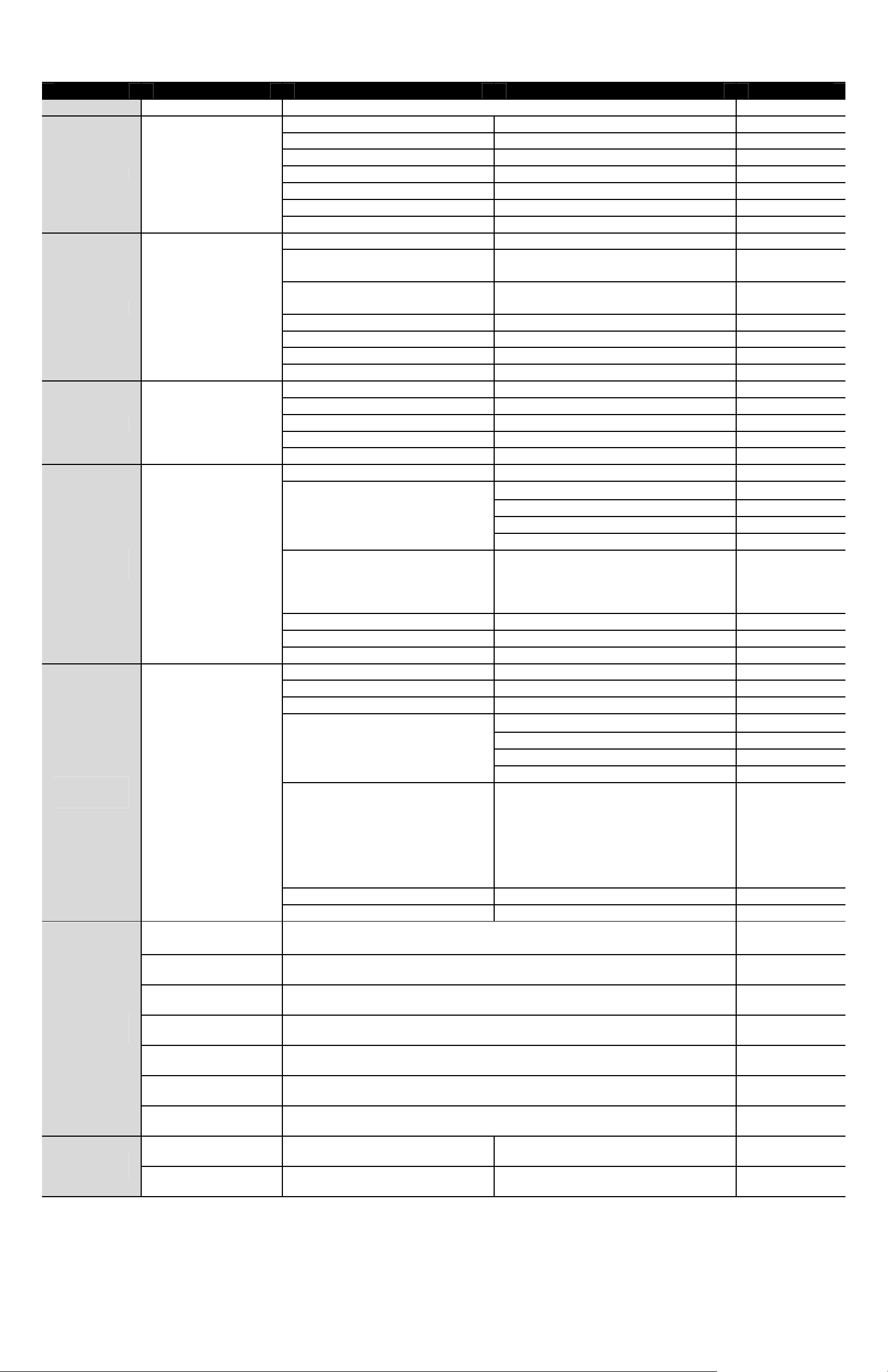
A
A
R
R
Item Layer 1 Layer 2
EXIT+ SAVE:
AUTO
IR
FUNCTION
BACKLIGHT ON, OFF
WBC MODE
SHADOW
FIGHTER
XDR
MANUAL
AUTO (Auto White Balance)
INDOOR
OUTDOOR
ATW (Auto-tracing WBC)
MANUAL
ON, OFF ON
THRESHOLD <MID>, <HI>, <LOW>
EXIT + SAVE: YES
IR MANUAL: <ON>, <OFF>
EXIT + SAVE: YES
R GAIN <000> ~ <127>
B GAIN <000> ~ <127>
EXIT + SAVE: YES
Layer 3
NTSC: <1/60> ~
<1/10000> SEC.
IRIS VALUE <F1.6>
GAIN VALUE
<-3>dB ~ <28>dB
EXIT + SAVE: YES
14
Default
AUTO
☆
SETUP
MENU 1
ENTER
ZOOM SPEED <8> 8
DIGITAL ZOOM <ON>, <OFF> OFF
SLOW SHUTTER <ON>, <OFF> OFF
2D N.R. <ON>, <OFF> ON
D.N.R.
IMAGE INVERSE <ON>, <OFF> OFF
FREEZE <ON>, <OFF> OFF
APERTURE <01> ~ <16> 07
EXIT <YES>
FLIP
3D N.R. <ON>, <OFF> ON
EXIT + SAVE: YES
<OFF>, <M.E.>, <IMAGE> (M.E.) OFF
EXIT + SET: YES
ADJUST MIN ANGL <-10> ~ <+10>
DEG
ANGLE ADJUSTER
SETUP
MENU 2
DEFAULT
CAMERA
ID DISPLAY <ON>, <OFF> ON
TITLE
DISPLAY
TITLE
SETTING
PRESET
ENTER
ON, OFF ON
<ON>, <OFF> OFF
<01> ~ <16> 01
PRESET SET <001>~<256>
PRESET RUN <001>~<256>
PROPORTIONAL ZOOM <ON>, <OFF> OFF
UTO CALI.
PASSWORD
OSD AUTO CLOSE <OFF>, <5> ~ <30> SEC. 20
SYSTEM RESET
EXIT <YES>
DJUST MAX ANGL <080> ~ <100>
DEG
EXIT + SET: YES
<ON>, <OFF>
<ON>, <OFF>
SYSTEM RESET <YES>
DEFAULT SYSTEM <YES>
EXIT <YES>
00
90
OFF
OFF
ENTE
ENTE
GVI Security
YES
R
1
01
01
A
1
01
1
A
GO
Y
A
1
A
A
A
A
Y
Item Layer 1 Layer 2
EXIT
SEQUENCE LINE
SEQUENCE POINT
PRESET POS.
SEQUENCE ENTER
AUTOPAN ENTER
CRUISE ENTER
HOME
SETTING
ALARM
SETTNG
ENTER
ENTER
SPEED
DWELL TIME
RUN SEQUNECE
EXIT
UTOPAN LINE
START POINT
END POINT
DIRECTION
SPEED
RUN AUTOPAN
EXIT
CRUISE LINE
RECORD START
RECORD END
RUN CRUISE
EXIT
HOME FUNCTION
SELECT MODE
PRESET POINT
SEQUENCE LINE
AUTOPAN LINE
CRUISE LINE
RETURN TIME
EXIT
LARM PIN
LARM SWITCH
LARM TYPE
ALARM ACTION
PRESET POINT
SEQUENCE LINE
AUTOPAN LINE
CRUISE LINE
Layer 3
<1> ~ <8>
<01> ~ <64>
<001> ~ <255>, <END>
<01> ~ <15>
<000> ~ <127> SEC.
ENTER
<YES>
<1> ~ <4>
<TO FIND>,
<TO SAVE>
<TO FIND>,
<TO SAVE>
<RIGHT>, <LEFT>
<01> ~ <04>
<1> ~ <8>
ENTER
ENTER
ENTER
ENTER
<ON>, <OFF>
PRESET
SEQUENCE
UTOPAN
CRUISE
<001> ~ <256>
<001> ~ <008>
<001> ~ <004>
<001> ~ <008>
<001> ~ <128> MIN.
ENTER
ES
<1> ~ <8>
<ON>, <OFF>
<NO>, <NC>
PRESET
SEQUENCE
UTOPAN
CRUISE
<001> ~ <256>
<001> ~ <008>
<001> ~ <004>
<001> ~ <008>
15
Default
ENTE
001
000
Right
OFF
☆
001
001
OFF
NC(NO)
☆
001
ALARM
DETECT
PRIVACY
MASK
DWELL TIME
EXIT
DETECT SWITCH <ON>, <OFF> OFF
DETECT MODE <MOTION>
BLOCK MODE NONE; MOTION: <ON>, <OFF>
FRAME SET NONE; MOTION: <01> ~ <04>
FRAME DISABLE NONE; MOTION: <01> ~ <04>
THRESHOLD NONE; MOTION: <001> ~ <255>
EXIT YES
PRIVACY SWITCH <ON>, <OFF>
TRANSPARENCY <ON>, <OFF>
<001> ~ <127> SEC., <ALWAYS>
ES
LWAYS
GVI Security
R
V
V
YES
R
Y
A
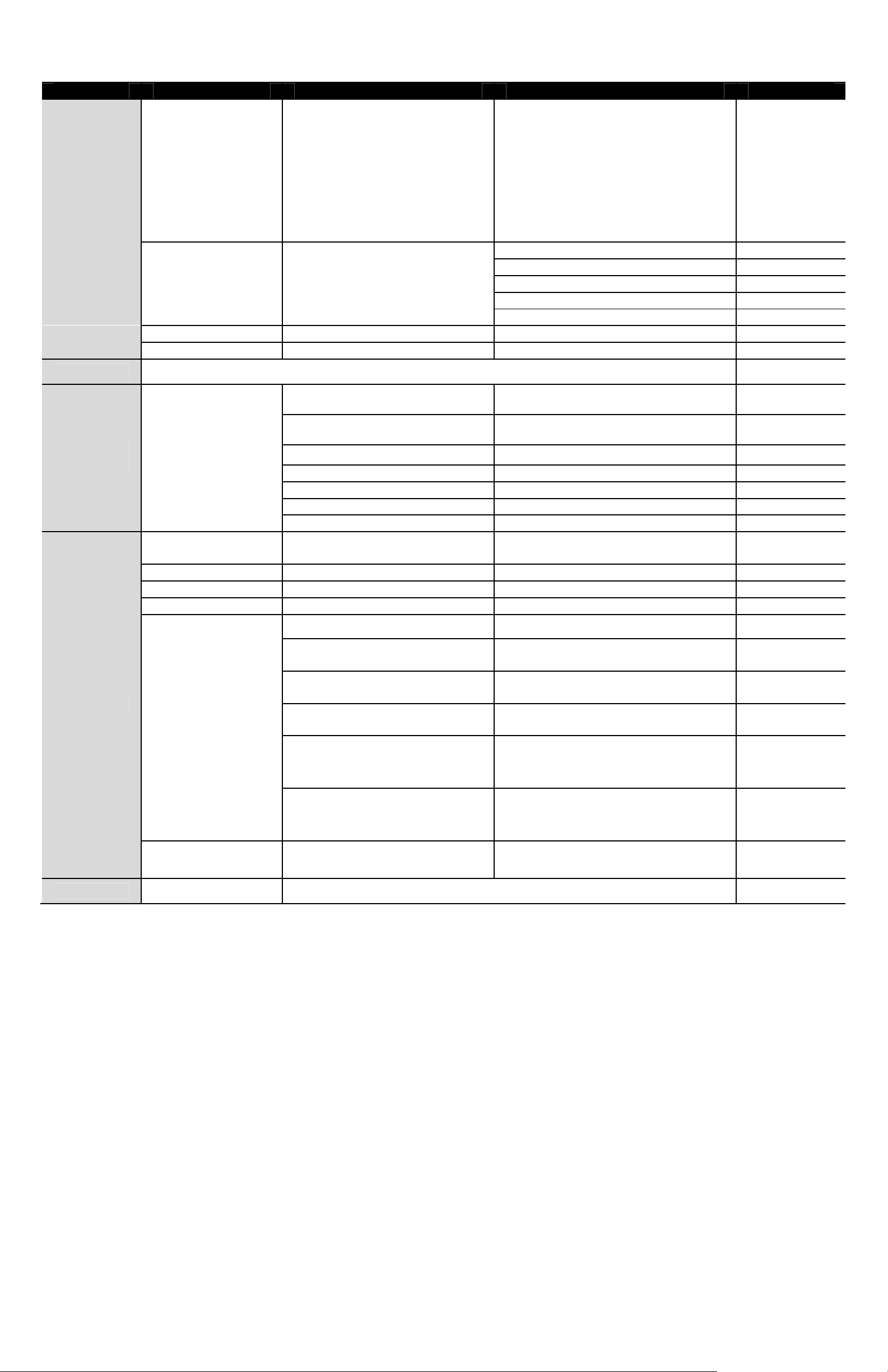
Item Layer 1 Layer 2
<BLACK>, <WHITE>,
COLOR
SET MASK <01> ~ <16>
CLEAR MASK <01> ~ <16>
EXIT
LANGUAGE ENGLISH, PORTUGUESE, SPANISH, FRENCH, GERMAN, ITALIAN ENGLISH
<RED>, <GREEN>, <BLUE>,
<CYAN>,
<YELLOW>,<MAGENTA>
Layer 3
H CENTER: L/
CENTER: D/U
H SIZE <000> ~ <080>
SIZE <000> ~ <060>
EXIT + SAVE
Default
000
000
16
TIME
SETTING
SCHEDULE
TIME DISPLAY <ON>, <OFF> OFF
SET YEAR <00> ~ <99>
ENTER
SCHEDULE
SWITCH
POINT <01> ~ <32>
HOUR <00> ~ <23>
MINUTE <00> ~ <59>
MODE
SET MONTH
SET DAY
SET HOU
SET MINUTE
EXIT+SAVE
<ON>, <OFF> OFF
NONE NO FUNCTION
PRESET
SEQUENCE
AUTOPAN
<01> ~ <12>
<01> ~ <31>
<00> ~ <23>
<00> ~ <59>
ES
01
00
00
PRESET POINT
<001> ~ <256>
SEQUENCE LINE
<001> ~ <008>
UTOPAN LINE
<001> ~ <004>
☆
CRUISE
IR FUNC.
SCHEDULE RESET YES
EXIT OSD YES
CRUISE LINE
<001> ~ <008>
IR FUNCTION <AUTO>, <ON>,
<OFF>
3.3 Configuration Menu
The detailed functions and parameter setting of the PTZ dome can be set by the OSD (On Screen Display)
menu with a control device such as a control keyboard. The tables below show each page of the OSD menu.
Additionally, Appendix B provides a table for user’s setting record.
To enter the OSD menu of the selected camera, press <CAMERA MENU> key on the control keyboard
and hold for 3 seconds to enter the OSD menu.
To select the setup item, use direction keys on keyboard to move the OSD cursor in the OSD menu.
To setup item, use direction keys on keyboard to move the OSD cursor in the OSD menu. For items with
→, press right/left direction keys on the control keyboard to select. For items with ↓, press the <CAMERA
MENU> key on the control keyboard to enter the sub menu. For items with →↓, users can use the right/left
direction keys to select functions, and then press the <CAMERA MENU> key on the control keyboard to
enter their sub menu. For further detailed setup procedures, please refer to the user’s manual of your
installed control devices.
NOTE: In the OSD menu, the <Camera Menu> key functions as “Enter” and “Exit.”
GVI Security
 Loading...