

Page 1
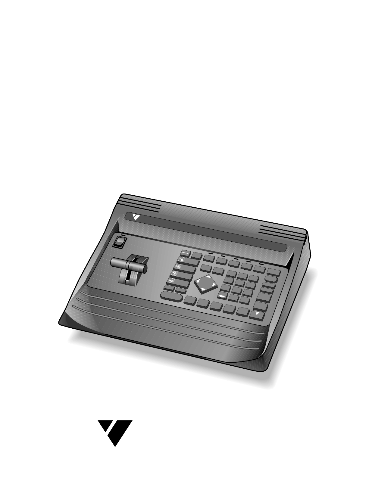
The Video Editing Company
VI DE ONICS
VIDEON ICS
DIGIT AL VIDEO MIXER
1
2
3
4
5
6
7
8
9
0
OK
A
B
C
D
COLOR
S
E
T
U
P
LEARN
CHROMA
K
E
Y
COMPOSE
DISPLAY
DEMO
SHIFT
PLAY
(AUTO TAKE)
FREEZE
SPEED
ZO
O
M
/
P-IN-P
WIPE
FADE /
DISSOLVE
B
A
C
K
BORDER
COLOR
COLOR
A
B
C
D
C
O
L
O
R
AUDIO
VIDEO
IN
P
U
T
F/X
C
U
T
➔
C
U
T
➔
C
U
T
➔
C
U
T
➔
C
U
T
➔
REVERSE
FLIP
Videonics MX-1 Digital V ideo Mixer
INSTRUCTION
MANUAL
Page 2
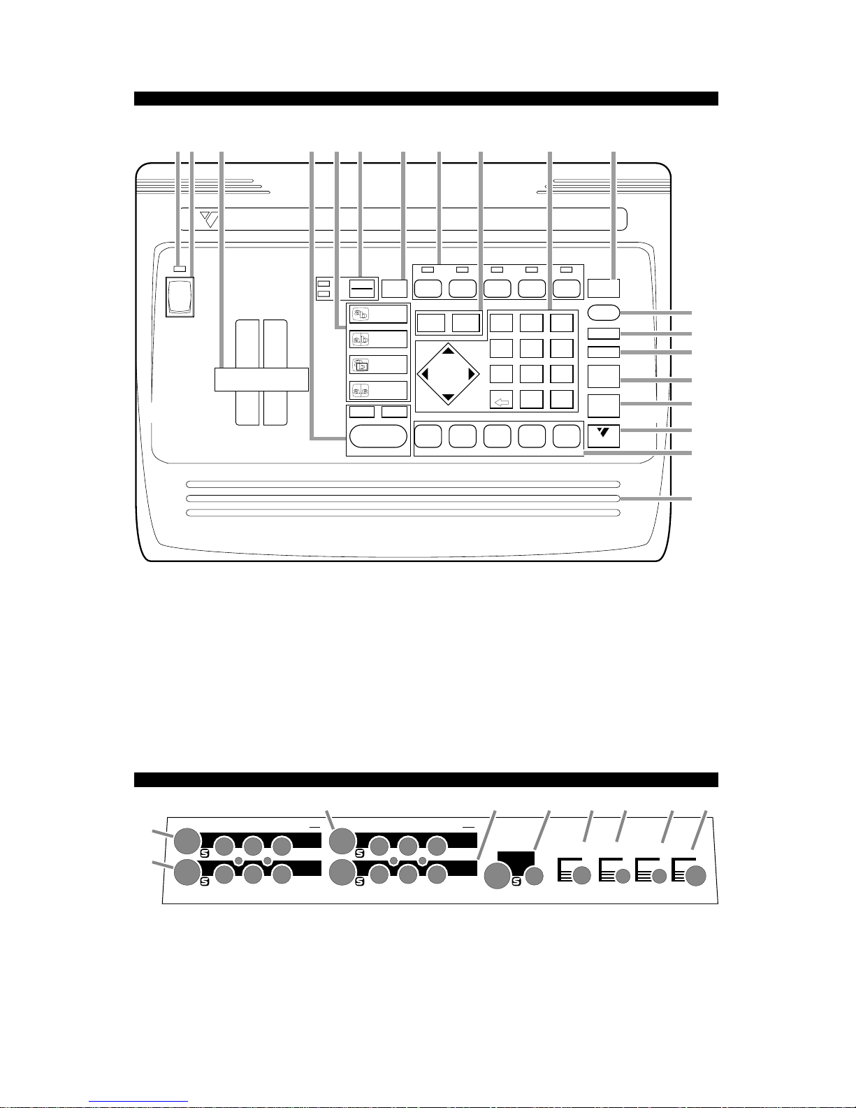
1. POWER INDICATOR
2. POWER SWITCH
3. TAKE BAR (FOR MANUAL TRANSITIONS)
4. AUTO-TAKE, AUTO-TAKE SPEED, AND VIDEO
FREEZE BUTTONS
5. TRANSITION EFFECT BUTTONS
6. AUDIO/VIDEO SELECTOR AND INDICATOR
7. INPUT EFFECTS (MOSAIC, STROBE, ETC.)
BUTTON
8. 4-INPUT SWITCHER CONTROLS, INDICATORS
9. BORDER AND BACKGROUND COLOR BUTTONS
10. TRANSITION-EFFECT SELECTION BUTTONS,
ARROW KEYPAD
11. PREVIEW MONITOR DISPLAY SWITCH
12. DEMO BUTTON
13. SETUP SCREEN BUTTON
14. SEQUENCER “LEARN” BUTTON
15. CHROMA KEY BUTTON
16. COMPOSE BUTTON
17. SHIFT
18. NEXT-SOURCE SELECTORS
19. ERGONOMIC PALM REST
CONTROLS
INPUT
F/X
PLAY
(
AUTO TAKE
)
BACK
COLOR
BORDER
COLOR
AUDIO
VIDEO
ZOOM /
P-IN-P
FLIP
WIPE
FADE /
DISSOLVE
COMPOSE
CHROMA
KEY
DEMO
SETUP
LEARN
DISPLAY
CUT ➔
ABCD
COLOR
7
4
0
859
6
123
SPEEDFREEZE
SHIFT
ABCD
COLOR
CUT ➔ CUT ➔ CUT ➔ CUT ➔
VIDEONICS
OK
REVERSE
DIGIT AL VIDEO MIXER
23 456 7 9 10 11
12
13
14
15
16
17
18
19
81
REAR PANEL
PREVIEW
OUT
POWER
HEAD
PHONE
IN 4
IN 1
IN 2
OUT
IN 3
CONTROL
(
GPI
)
POWER
CONTROL HEADPHONE PREVIEW V — IN 4 — S RLV S RLV S
IN 3
OUT
IN 2
IN 1
V
LRV
LRVLRV
LRV
A
B
EC
D
FG HI
A. INPUT 1
B. INPUT 2
C. INPUT 3
D. INPUT 4 (VIDEO ONLY)
E. OUTPUT
F. PREVIEW/CONTROL SCREEN OUTPUT
(COMPOSITE VIDEO)
G. HEADPHONE OUT
H. CONTROL INPUT (GPI TRIGGER)
I. POWER
INPUTS 1-3 AND MAIN OUTPUT INCLUDE JACKS FOR S-VIDEO, COMPOSITE (RCA-STYLE) VIDEO, AND RIGHT
AND LEFT AUDIO. JACKS ARE LABELED UPSIDE DOWN AT TOP OF PANEL TO FACILITATE CONNECTIONS
WITHOUT TURNING UNIT AROUND.
Page 3
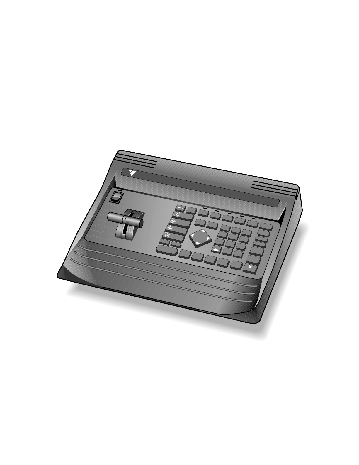
Videonics MX-1 Digital V ideo Mixer
INSTRUCTION
MANUAL
MX-1 Digital Video Mixer Instruction Manual • MANL-0521-02 • © 1994 Videonics, Inc.
The Videonics logo, Thumbs Up, and Videonics Video TitleMaker are registered trademarks
of Videonics, Inc. MX-1 is a trademark of Videonics.
Hi8 is a trademark of Sony Corporation. VHS is a registered trademark of JVC. Other product
and brand names may be trademarks or registered trademarks of their respective companies
and are hereby acknowledged.
Television screens are simulated.
Subject to change without notice.
This device is not to be used for the unauthorized copying of copyrighted material.
Videonics, Inc., 1370 Dell Avenue, Campbell, CA 95008 USA; 408-866-8300
VIDEON ICS
DIGIT AL VIDEO MIXER
1
2
3
4
5
6
7
8
9
0
OK
A
B
C
D
COLOR
S
E
T
U
P
LEARN
CHROMA
K
E
Y
COMPOSE
DISPLAY
DEMO
SHIFT
PLAY
(AU
TO T
AKE)
FREEZE
SPEED
ZO
O
M
/
P-IN-P
WIPE
FADE /
DISSOLVE
B
A
C
K
BORDER
COLOR
COLOR
A
B
C
D
C
O
L
O
R
AUDIO
VIDEO
IN
P
U
T
F/X
C
U
T
➔
C
U
T
➔
C
U
T
➔
C
U
T
➔
C
U
T
➔
REVERSE
FLIP
Page 4

Chapter 1 • Introduction ...............1
In a Hurry? ................................................ 1
Helpful Sections ....................................... 1
For More Information ................................ 1
What is a Video Mixer?............................. 2
What is the MX-1? .................................... 2
Applications and Setups .......................... 3
Editing with the MX-1 ............................... 4
Chapter 2 • QuickStart ..................5
Chapter 3 • Installation ............. 10
Connections: Overall Concept............... 10
What You’ll Need .................................... 10
Types of Input and Output Jacks .......... 11
Types of Cables Used with
the Video Mixer .................................... 12
How Many Monitors? .............................. 12
IN and OUT Markings ............................ 13
Connecting Power, Outputs, Monitors... 13
Connecting Sources............................... 15
Chapter 4 •
Connecting Editing Equipment . 18
Processing the Inputs vs. the Output .... 18
Adding Titles .......................................... 19
Audio Mixing........................................... 19
Edit Control ............................................. 19
Chapter 5 • Setup Screen .......... 20
Defaults................................................... 20
Automatic Connection............................ 20
Routing the Inputs .................................. 21
The Setup Screen................................... 21
Advanced Setup..................................... 22
Chapter 6 • Basic Controls........ 25
Built-In Demo.......................................... 25
The PREVIEW Screen............................. 25
Source Previews..................................... 26
Preview Image Quality ........................... 26
CURRENT and NEXT Source Selection. 26
Transition Controls ................................. 26
Viewing a Transition ............................... 27
Switching the Display............................. 27
Video Quality .......................................... 27
Chapter 7 • Switching (Cuts)..... 28
Switching to a Specific Source .............. 28
Cutting Back and Forth .......................... 28
Soft Cuts ................................................. 29
Chapter 8 • Transitions .............. 30
The Basic Concept................................. 30
Which Source is Which?......................... 31
Changing the CURRENT Source ........... 31
Choosing the NEXT Source ................... 31
Choosing the Transition Effect............... 32
Executing the Transition......................... 33
Setup for the Next Transition ................. 34
Performing the Next Transition .............. 34
Reverse................................................... 34
Chapter 9 • Audio Control.......... 36
Connecting Sound Sources ................... 36
The AUDIO/VIDEO control ..................... 36
Choosing a Sound Source ..................... 36
Sound Source Indicators ....................... 36
Sound Strategies .................................... 37
Headphones ........................................... 38
Chapter 10 •
Borders and Backgrounds ......... 39
The Solid Color Background.................. 39
Choosing Colors..................................... 39
Turning the Border On and Off .............. 40
Defining a Color...................................... 40
Chapter 11 • Input Effects......... 42
Defining Input Effects............................. 42
Chapter 12 • Freeze .................... 45
Stop Motion............................................. 45
Chapter 13 • Chroma Key........... 46
What is Chroma Key ?............................ 46
Advanced Feature.................................. 46
An Example ............................................ 46
Setting up the Picture for Chroma Key .. 47
Hints for Chroma Key Setup .................. 47
Performing a Chroma Key...................... 48
Ending Chroma Key ............................... 50
Contents
Page 5

Chapter 14 • More Effects......... 51
Tint Effect................................................ 51
The “Thin Man” Effect............................. 51
Luminance Key....................................... 51
“Film Look” Effect ................................... 52
Color Bars............................................... 52
Black-Burst Generator............................ 52
Color Generator...................................... 53
Chapter 15 •
Picture-In-Picture (PIP) ............. 54
Definitions ............................................... 54
Applications............................................ 54
Creating a PIP Image ............................. 54
Ending PIP Mode.................................... 56
Chapter 16 • Compose ................ 57
What is Compose? ................................. 57
Rules for Compositions .......................... 58
Choosing the Background ..................... 58
Positioning and Sizing an Element ........ 58
Placing the Element ............................... 59
Adding More........................................... 60
Making Changes .................................... 60
Recording the Result.............................. 60
Ending Compose Mode ......................... 60
Chapter 17 •
Sequences (LEARN mode) .......... 61
What is LEARN Mode? ........................... 61
Notes....................................................... 61
Learning a Sequence............................. 61
Playing the Sequence ............................ 62
Ending Sequence Playback................... 62
Changing the Sequence ........................ 62
Number of Steps .................................... 62
Chapter 18 • TBC ......................... 64
Skip This Chapter? ................................. 64
What is a TBC? ....................................... 64
Using the TBC ........................................ 64
Dual TBC Mode ...................................... 64
Frame Rate Lock Setting........................ 64
Vertical Interval Data .............................. 65
Answers About the MX-1’s TBC............. 65
Contents
Chapter 19 •
Editing and Other Applications 67
Live Mixing ............................................. 67
Editing with Untimed Sources................ 67
Loosely Synchronized Tapes................. 67
Single-Source (A/A) Editing ................... 68
A/B Roll Editing....................................... 69
Titles ....................................................... 70
Other Accessories.................................. 71
GPI Trigger ............................................. 71
Automatic Input Scan Mode .................. 71
Chapter 20 • Video Quality ........ 72
Preview Image Quality ........................... 72
Video Scaling Artifacts ........................... 72
Slide/Compress Motion Effects.............. 72
Freeze Quality ........................................ 73
Upside-Down Video ............................... 73
Video Processing Artifacts..................... 73
Chapter 21 • Specifications ...... 74
Chapter 22 • Glossary ................. 75
Chapter 23 • Effects List ........... 81
Terms and Abbreviations ....................... 81
“Top 30” Effects...................................... 81
Page 6

VIDEONICS DIGITAL VIDEO MIXER PAGE 1
Chapter 1 • Introduction
Congratulations on your purchase of the Videonics MX-1 Digital
Video Mixer. The MX-1 combines everything you need to work with
multiple video sources: A four-input video production switcher,
video mixer (dissolve unit), frame synchronizer/TBC (Time Base
Corrector) and special effects generator.
In a Hurry?
If you want to get started quickly, see the QuickStart section, Chapter 2.
Helpful Sections
The MX-1 is a sophisticated video production tool. Some of the concepts
used in this manual may be new to you. You may wish to consult these
sources:
• The Digital Video Primer (a separate pamphlet, included with the MX-1)
explains the basic concepts of mixing video signals and using digital
special effects.
• The Glossary section of this manual defines the specialized terms used in
the manual.
• A complete index is included at the back of this manual. It refers you to
appropriate pages in the Digital Video Primer as well as to the appropriate
sections of this manual.
For More Information...
...send in your registration card so we can keep you informed of new
developments and send you our newsletter
*
. Note that Videonics does not
sell its mailing list. Your name and address will remain confidential.
*
The newsletter and certain other services are available for Videonics customers in the U.S.
and Canada. Elsewhere, contact your Videonics distributor or retailer.
Page 7
PAGE 2 VIDEONICS DIGITAL VIDEO MIXER
What is a Video Mixer?
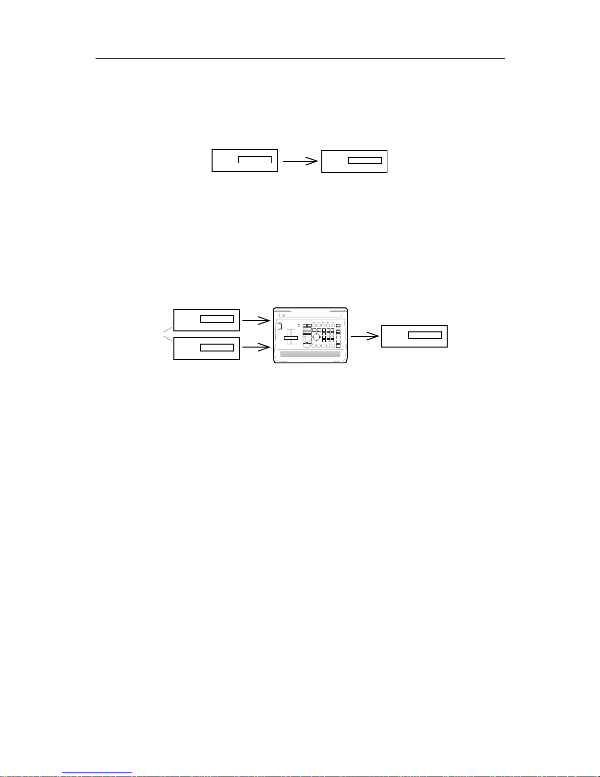
The Digital Video Primer explains mixer basics in detail but here is an
overview.
❷
❶
In the simplest form of video production, a video tape is played by one
machine (∂ ) and the resulting signal is recorded on a blank tape by a second
machine (∑). The player and recorder are coordinated (either manually or
automatically) so that the desired video material is recorded on a blank tape.
Note that there is only one source of incoming video and only one picture is
on the output screen at any given moment.
More advanced video productions use two sources of video (∂ ) and mix
them together:
❷
❸
❶
VIDEONICS
DIGITAL VIDEO MIXER
With the inclusion of a video mixer (∏), a wonderful thing happens: You
can put two sources on the screen at once. For instance, you could show a
great pass on one side of the screen and the coach’s reaction on the other. Or
you might begin your production with a shot of the ball and have it slowly
fade away while a long shot of the playing field fades in (a dissolve). Many
other transitions and effects are possible.
A video mixer is required to make this happen. It provides the electronics
needed to mix two signals and has controls that allow you to select which
source or sources are being sent to the recorder (∑) and which transitions are
being used.
A mixer can be used with great benefit in simple setups as well as complex
ones, but its use is required whenever two sources will share the screen.
What is the MX-1?
The MX-1 is a video mixer with many additional features. (See the Glossary and Digital Video Primer for descriptions of the following functions.)
Four-Input Synchronized Switcher. The MX-1 has four inputs, not just
two, so you can leave all your sources connected. This capability is also
handy for live production settings in which up to four cameras or other
sources are available. The switcher is synchronized, which means there are no
picture disruptions when sources are switched.
Frame Synchronizer and Mixer. Any two inputs can be mixed together
using a variety of transitions (wipes, dissolves, etc.). The frame synchronizer
makes it possible to mix independent video signals.
Page 8

VIDEONICS DIGITAL VIDEO MIXER PAGE 3
Picture-in-Picture (PIP). Two pictures can share the screen in various
configurations, including picture-in-picture, in which one source occupies a
small area and the other takes the rest of the screen. Example: The inset can
show the scoreboard while the rest of the picture shows the playing field.
Effects Generator. Effects can be used to enhance a source or to transition
between two sources.
TBC (Time Base Corrector). The time base of the MX-1’s output is always
automatically corrected. This makes the picture stable even when the inputs
are not.
Chroma Key and Luminance Key. “Keying” replaces parts of one picture
with another, based on their lightness (luminance key) or color (chroma key).
For example, you might shoot a picture of a football player in front of a solid
color screen and later show the shot with a shot of the football stadium keyed
into the solid color area behind.
Compose. The MX-1 includes a video painting system which can combine
video stills, color shapes, and moving video on one screen. You could create a
screen that contains a video still of the coach with a red border, combined
with a moving video of the players in action and stripes in the team colors.
Audio Mixer. Basic audio control is provided, with the ability to have the
sound change along with the video, or to have a constant sound source while
the picture changes. Audio can come from a video source or from external
audio devices.
Applications and Setups
The most common uses of the MX-1 are for video production and live
settings. Chapter 19, “Editing and Other Applications,” describes these functions in more detail and explains how they are accomplished with the MX-1.
Multiple-Source Video Production. In a video production setup, one or
more VCRs, camcorders, video disc players, cameras, title generators, computer graphics systems, or other video sources are connected to the MX-1’s
four inputs. The output is connected to a VCR which records the result.
The MX-1 determines what will be sent to the recording VCR. While the
original tapes play, the operator can switch between any of the inputs; use
dissolves or other transitions to go from one video to another; add special
effects to any source; and use advanced features such as compose and chroma
key to jazz up the production.
Single-Source Use. The MX-1 is useful even when there is only one video
tape playing. It supports A/A roll, a method for creating interesting transitions with a single source, and its digital effects, such as picture freeze,
posterization, and zooms, can liven up any production. It can be used with a
titler to mix and superimpose titles. The TBC improves the picture, especially
when making multiple-generation copies, by removing the jitter that is
common to most VCRs. And the Compose feature can be used to create
additional images that can enhance the production.
Live Video. In a live production setup, an event is recorded as it occurs.
The Mixer allows the use of multiple cameras. While a single camera is
Page 9

PAGE 4 VIDEONICS DIGITAL VIDEO MIXER
restricted to one point of view, multiple cameras catch more of the action. For
instance, a camera at the end of the field can be connected to one input while
a camera at the side goes to another. A third might be aimed at the announcer. The operator can switch or transition between them as the action
progresses. Taped sources can be included, too. Perhaps a VCR loaded with
shots of the ball players practicing could be used at appropriate moments. A
titler could be used to superimpose titles on the action.
Editing with the MX-1
Note that the MX-1 is not an edit controller — that is, it does not control
the VCRs and camcorders. You can control the decks manually or by using
an external edit controller (such as those made by Videonics). See Chapter 19,
“Editing and Other Applications” for more information.
In addition, the MX-1 can be used with other video production equipment, such as title generators and video processors. Contact Videonics for
more information on its full line of video production equipment.
Page 10
VIDEONICS DIGITAL VIDEO MIXER PAGE 5
Chapter 2 •Chapter 2 • QuickStart
Whether you’re a video expert looking for just the basic steps or a
beginner who wants instant gratification, this chapter will have you
mixing in minutes! If you run into problems or would like more
information, refer to the table of contents or the index to locate a
more complete discussion.
PREVIEW
OUT
POWER
HEAD
PHONE
IN 4
IN 1
IN 2
OUT
IN 3
CONTROL
(
GPI
)
POWER
CONTROL HEADPHONE PREVIEW V — IN 4 — S RLV S RLV S
IN 3
OUT
IN 2
IN 1
V
LRV
LRVLRV
LRV
VIDEO
OUT
AUDIO
OUT
VIDEO
OUT
AUDIO
OUT
A
BC DEF
VIDEOINAUDIO
IN
VIDEO
IN
Setup and Installation
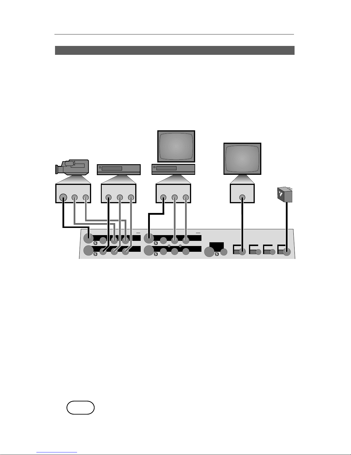
• Connect the power supply (F) and turn the unit on, confirming that
the power light comes on.
• Connect the MX-1’s OUT jacks to the VIDEO and AUDIO IN jacks of a
VCR (D). Connect a television/monitor to the VCR in the normal
fashion (A), so that you will be able to see the VCR’s output. Turn the
television and VCR on.
• Connect the MX-1’s PREVIEW OUT jack to the VIDEO IN jack of a
second monitor (E).
Note: These instructions assume a two-monitor setup. If you are using only
one monitor, connect it to PREVIEW.
• Connect a camcorder, VCR or other source to IN 1 (B). Connect a
second source to IN 2 (C). Turn on the video sources and start the
tapes rolling.
• Press SHIFT and AUDIO/VIDEO at the same time and the MX-1 will
automatically find and use the inputs that have video signals connected.
Demo
• Press DEMO. You should see the two sources alternating, with a variety
of transition effects in between. (If only one source is connected, the
demo will perform transitions from that source to itself.)
DEMO
Page 11
PAGE 6 VIDEONICS DIGITAL VIDEO MIXER
• Press any key to stop the demo.
The PREVIEW screen
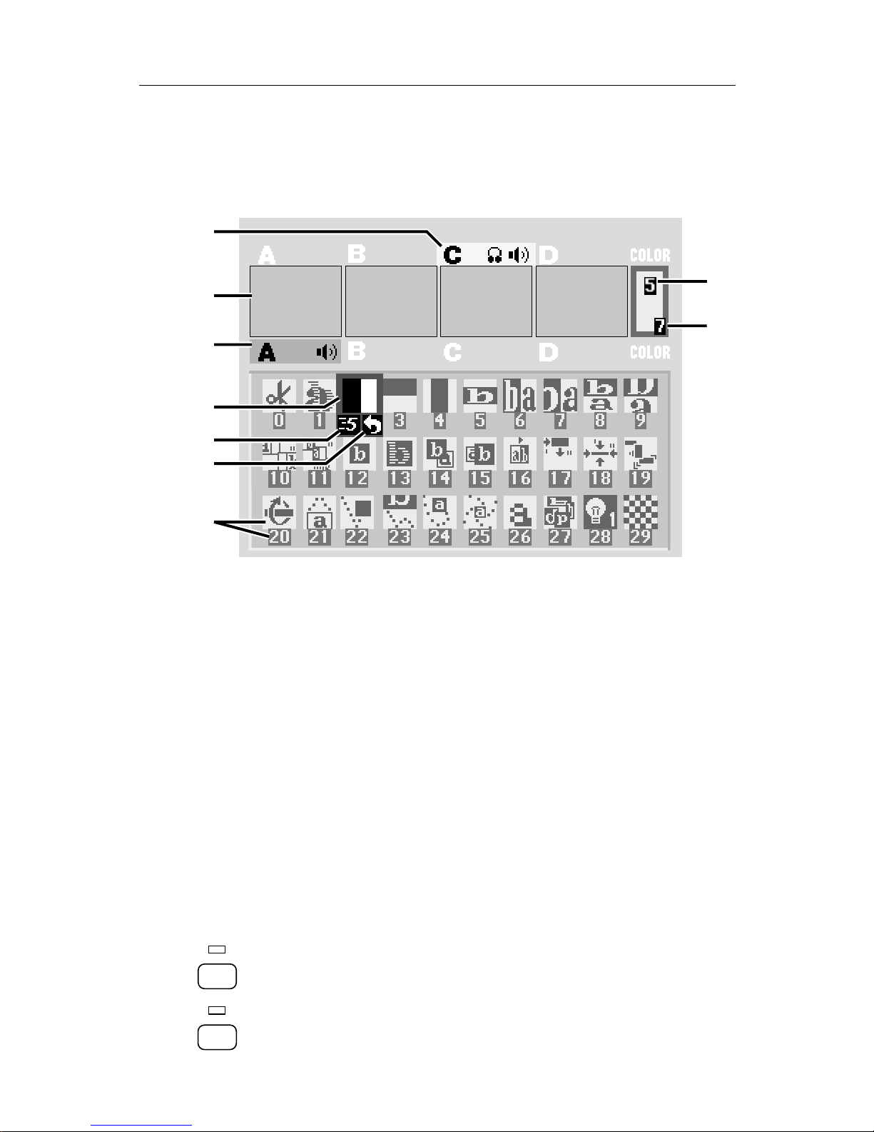
• You should see the following (with some slight differences) on the
PREVIEW monitor screen:
A
D
E
F
C
H
J
B
G
A
D
E
F
C
H
J
B
G
• This screen shows you four preview images (B) — these are your video
inputs in miniature.
Note that the preview images are reduced size and frame rate (that is,
they don’t change as quickly as a single-source video monitor’s image). Depending on the type of video connected to the inputs, you
may also see lines outside the preview images. Preview image quality
does not affect the output.
• The PREVIEW screen shows you the three most important things you
need for accomplishing a transition:
Which input is the CURRENT source (A) — that is, which one is
currently on the OUTPUT monitor. The current source is highlighted in
yellow.
The NEXT source (C) — that is, the one that will appear on the
OUTPUT monitor after the transition is complete. The NEXT source is
highlighted in green.
An array of symbols (G), each of which represents an effect that can be
used when transitioning between sources. A blue highlight (D) shows
which effect will be used next.
• The PREVIEW screen also shows the speed (E) and direction (F) that
will be used for the next transition and the background (H) and border
(J) colors.
Cutting Between Sources
• Press CUT→A. The light above the button will come on and the
OUTPUT monitor will show whatever is plugged in to the input labeled
CUT ➔
A
B
CUT ➔
Page 12

VIDEONICS DIGITAL VIDEO MIXER PAGE 7
IN 1. The yellow highlight above preview A tells you A is currently the
active input.
• Press CUT→B. The B light will come on and the OUTPUT monitor will
show whatever is plugged into IN 2. B should be highlighted in yellow.
• If you have anything plugged into IN 3 or IN 4, the sources can be seen
by pressing CUT→C or CUT→D.
Borders and Solid Color Backgrounds
• Press CUT→COLOR. The word COLOR above the color sample will
highlight and the light above the button will come on. The OUTPUT
monitor will show a solid color screen.
To change the color, press BACK COLOR. Each time you press it, the
color will change in the background color sample (H) and at the
output. Continue to press the button until you see a color you like.
• You can also define a border to be used at the edge of most wipes.
Press BORDER COLOR and the color around the background color
sample (J) will show you the new choice.
• You can define your own colors as well. See Chapter 10, “Borders and
Backgrounds.”
Setting up a Transition
• Now, let’s switch from one video source to another using a transition
in between. We will go from A to B using a horizontally-moving curtain
wipe.
• Switch to A by pressing CUT→A.
• Pick the NEXT source (the one you want to see after the transition is
complete). In this case, we want to go to B, so press the B button at the
bottom of the control panel (not the CUT→B button).
ABCD
COLOR
A green highlight appears below preview image B and the light above
the CUT→B button flashes to tell you B is the NEXT source. Nothing
else happens on the screen because right now, you are only setting up
the transition.
• Next, choose the wipe effect by highlighting the appropriate symbol in
the effect palette. The fastest way to do this is to press WIPE. This
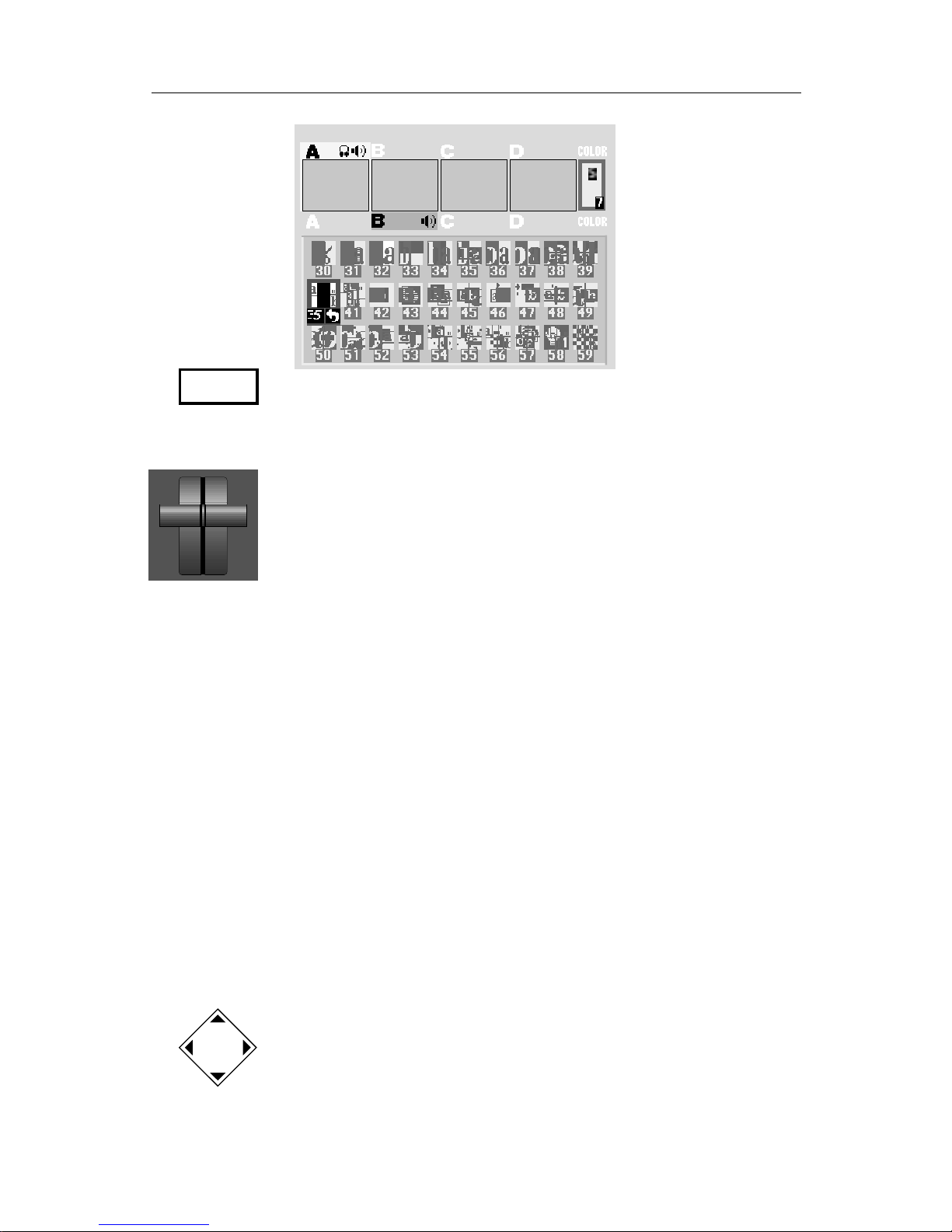
highlights the symbol for effect 30, the most common wipe, a horizontally-moving wipe. In this case, however, we want a different wipe. Use
the down-arrow key to highlight transition effect number 40. The
screen should look like this (although the direction and speed indicators may be different):
COLOR
CUT ➔
CD
CUT ➔ CUT ➔
Page 13
PAGE 8 VIDEONICS DIGITAL VIDEO MIXER
• The screen now shows: The CURRENT source (A), the NEXT source (B),
and the desired effect (the horizontally-moving curtain wipe). Press
PLAY and the wipe will occur. Both the PREVIEW and OUTPUT screens
show the results.
• Notice that at the end of the wipe, B is on the OUTPUT monitor — it
has become the CURRENT source. The yellow highlight above the
preview images has changed to reflect that. Furthermore, A is now the
NEXT source and the green highlight has been changed to A.
You can easily wipe back and forth between A and B: Simply press PLAY
again and again.
Performing Transitions
• The PLAY button causes the effect to occur automatically at a fixed
speed. To change speeds, press the SPEED button. The speed indicator
under the transition effect will change. Press the button again until the
desired speed is displayed. 0 is the slowest speed, 9 is the fastest.
Try this now with various speeds: Change the speed and press PLAY.
• You can also use the manual control (the “T-bar,” or “Take Bar”) to
control the transition. To do this, set up the transition normally but
instead of pressing PLAY, simply move the bar. Nothing will happen
until the bar is all the way up or all the way down. Then the transition
will begin as you move the bar. You can move back and forth as you
wish. Try it!
• Most video productions use simple cuts a majority of the time. To cut
between any two sources (for instance, you could cut from A to C to
COLOR to D), use the CUT buttons.
There’s a quick way to cut back and forth between two sources (such
as A to B to A to B) using just the PLAY button, instead of having to
alternate between two CUT buttons:
• Press 0 to select effect 0 (the simple cut).
• Press PLAY again and again.
SPEED
Page 14
VIDEONICS DIGITAL VIDEO MIXER PAGE 9
• A solid color screen can be used as if it were a separate source. Press the
COLOR button at the bottom right and perform any effect, or use
CUT→COLOR.
Choosing Transition Effects
• Next, let’s try some other effects and different ways to select them.
The PREVIEW screen presents a “palette” of symbols, each represent-
ing a transition effect. A blue highlight shows which effect will be used
for the next transition.
Note that the first 30 symbols represent commonly used effects. You
may find that the majority of your work can be done with just these 30.
There are three ways to select an effect:
1 Using the arrow keys
Simply use the arrow keys to highlight the desired effect.
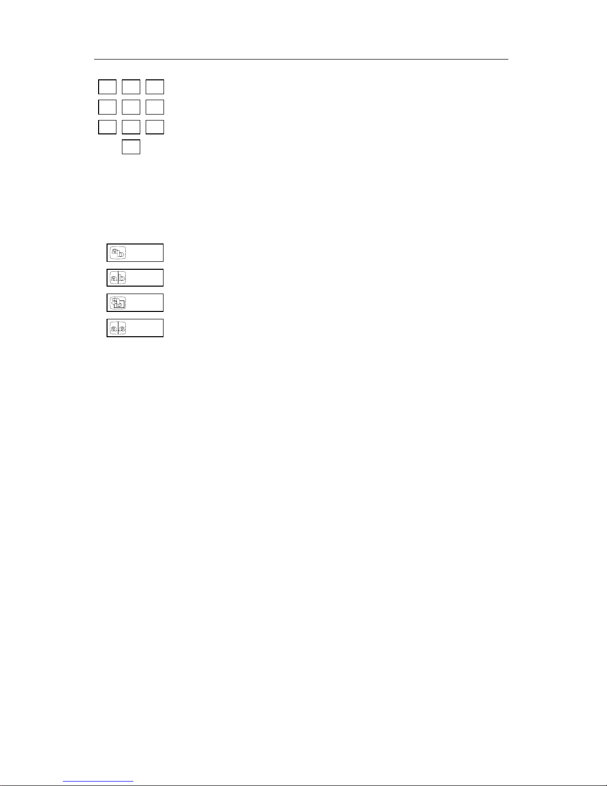
2 Using the number keys.
Every transition effect has a number, displayed on the PREVIEW screen
beneath the effect’s symbol. You can use the numbers to choose
effects. Try this now:
1 Press CUT→A to choose A as the CURRENT source.
2 Press B to make B the NEXT source.
3 Enter 106 using the number keys (press 1 then 0 then 6). You can
press OK to highlight the symbol, but it’s not necessary.
4 Press PLAY.
As you use the MX-1, you will memorize the numbers of the effects you
use the most. A list of effects is in the back of this manual and on the
Reference Card.
3 Using the large effect buttons.
The large effects buttons are a convenient way to locate some common effects families. Press WIPE, for instance, and the most basic wipe
is instantly highlighted. Press FLIP to choose a flip effect.
Similar effects are grouped together, making it easy to locate other
effects. Simply press a large effect button (such as WIPE) to select the
kind of effect you want, then use the arrow keys to select the exact
variation.
More...
Refer to the rest of this manual to learn about the many additional
features of the MX-1. You can:
• Freeze the picture.
• Separately control the sound.
• Apply input effects such as mosaic, paint (posterization), negative, and
more.
• Use chroma key and luminance key to combine parts of one picture
with parts of another.
• Compose your own pictures, made up of several stills, color rectangles,
and a moving picture.
• Rearrange the inputs so A, B, C, and D, and their audio channels come
from different rear panel jacks.
• Memorize a sequence of effects and play it back automatically.
ZOOM /
P-IN-P
FLIP
WIPE
FADE /
DISSOLVE
7
4
0
859
6
123
Page 15
PAGE 10 VIDEONICS DIGITAL VIDEO MIXER
Chapter 3 •Chapter 3 • Installation
Connections: Overall Concept
VIDEONICS
DIGITAL VIDEO MIXER
INPUTS
OUTPUT
PREVIEW
A
B
C
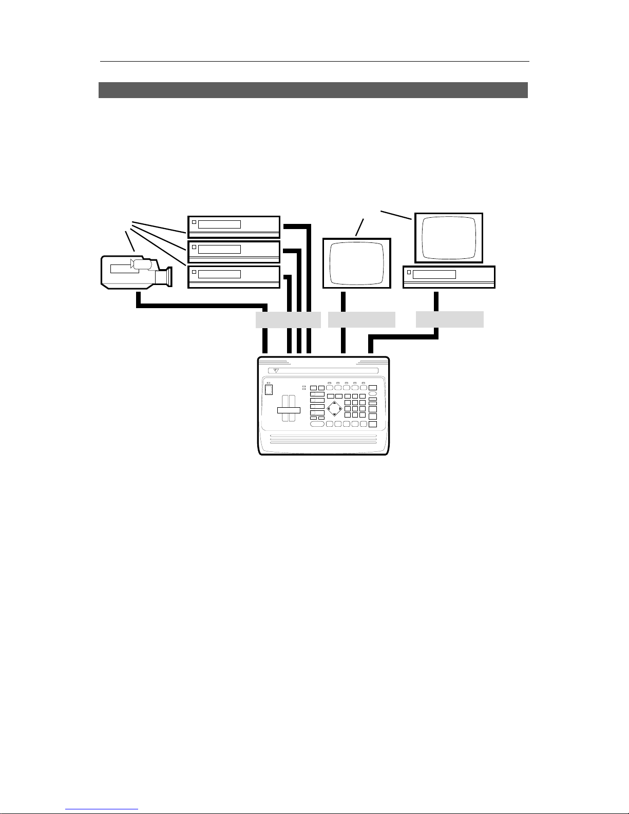
The MX-1 Digital Video Mixer can accept up to four audio/video sources.
It can send any of these to the output and can perform transitions between
any two sources.
The output is sent to a VCR and/or monitor (called the OUTPUT monitor).
A second monitor, called the PREVIEW monitor, is used to display all the
inputs in preview form. The PREVIEW monitor also shows the on-screen
controls used to operate the unit.
This chapter describes how to connect the inputs, outputs, and monitors.
Chapter 4, “Connecting Editing Equipment” goes further, explaining how to
attach editing equipment, such as an edit controller or title generator.
What You’ll Need
A One or more video sources. Any standard video source with composite
(RCA-style) or S-video (Y/C) outputs can be used, including VCRs,
camcorders, cameras, video disc players, title generators, and computers
with television outputs.
B A PREVIEW monitor and/or an OUTPUT monitor. (You can work with a
single monitor but having two will make your work faster and easier. See
the section later in this chapter, “How Many Monitors?”)
Page 16
VIDEONICS DIGITAL VIDEO MIXER PAGE 11
The PREVIEW monitor needs a composite (RCA-style) video input.
The OUTPUT monitor will be connected to your recording VCR (C ) in
most cases. Required connections depend on the VCR. You can use any
arrangement that will allow you to view tapes played on the VCR.
C A Record VCR. In a live setup, in which the results will be displayed
without being recorded, the VCR is optional, but most setups will include
the VCR.
• Video Cables. You will need at least one video cable for each input plus
one to connect the PREVIEW monitor and one to connect the Record VCR.
You will also need a cable to connect the OUTPUT monitor to the Record
VCR. The next section describes the types of cables.
Types of Input and Output Jacks
S-VIDEO AUDIO
AUDIOVIDEO
ANTENNA
ANT
INPUT
AUDIOVIDEO
❶
❷
❸
❹
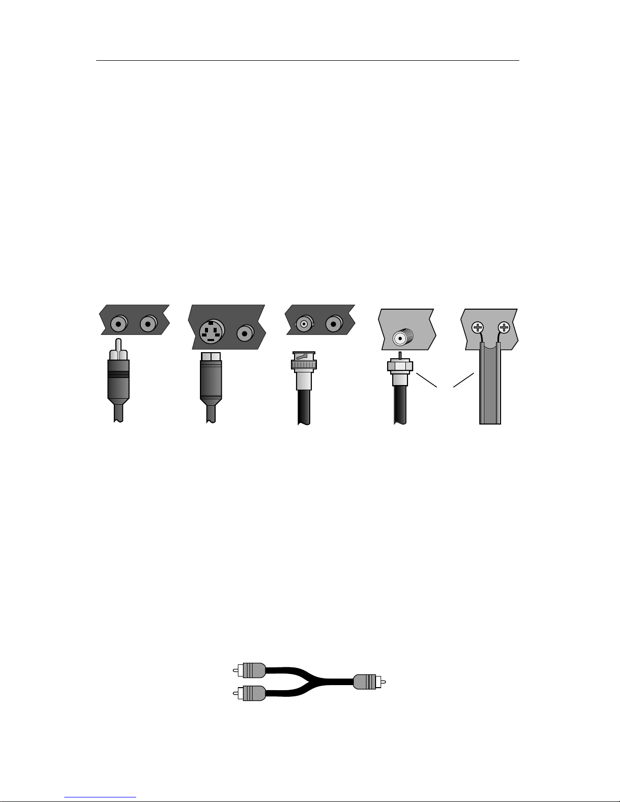
Video equipment commonly uses these cable types:
∂ Composite (RCA-style) video and audio
∑ S-video (Y/C)
∏ BNC video, used in some professional equipment
π RF cables (Coaxial cable and twin-lead antenna cable)
Audio
RF cables carry the audio signal along with the video. All the others
require a separate audio cable.
A stereo audio device (with separate L and R inputs or outputs) is connected using two RCA-style cables. A mono audio device is connected using
one RCA-style cable.
You may also need a Y-cable if you plan to connect a mono output to both
channels of a stereo device; or to connect a stereo output to a mono input.
Y-cable
Page 17

PAGE 12 VIDEONICS DIGITAL VIDEO MIXER
Types of Cables Used with the Video Mixer
• PREVIEW. The PREVIEW monitor must be connected via a composite
(RCA-style) cable.
• OUTPUT. You can connect the Mixer’s output to a monitor or VCR using
either an S-video (Y/C) or composite (RCA-style) cable. If you have a
choice, S-video is better than composite.
• Record VCR to OUTPUT monitor. If you are using a Record VCR with the
Mixer, the OUTPUT monitor can be connected to the VCR using an RF
(antenna/cable type) cable, composite (RCA-style) cable, or S-video (Y/C)
cable, depending on what types of jacks are available on the VCR and
monitor. If you have a choice, S-video is better than composite and com-
posite is better than RF.
• Sources. All other video devices can be either S-video or composite. If you
have a choice, S-video is better than composite.
• Mixed types.
If the output is connected using S-video jacks, you can mix cable types, using
composite for some inputs and S-video for others.
If the output is connected using composite (RCA-style) jacks, use composite for
all inputs as well. This will give a slightly better picture quality.
• BNC. If you plan to use equipment with BNC jacks, you will also need
RCA-BNC adapters.
• Audio. The Mixer uses RCA-style cables for all audio channels.
How Many Monitors?
Normally, the MX-1 is used with two monitors.
• The PREVIEW monitor contains the on-screen controls and previews of
all four inputs.
• The OUTPUT monitor shows the output, complete with all effects and
transitions, exactly as it will be recorded or displayed.
Single Monitor Setup
You can omit the OUTPUT monitor and use only a single monitor, connected to the PREVIEW output jack. With this setup, you will still see all the
pertinent action because the PREVIEW screen shows transitions while they
are being performed. However, dual monitors are recommended because:
• The OUTPUT monitor always shows you what is really being recorded or
displayed.
• Since the OUTPUT monitor doesn’t change to preview mode between
transitions, productions are easier to visualize.
• The PREVIEW monitor uses composite (RCA-style) jacks only.
Page 18
VIDEONICS DIGITAL VIDEO MIXER PAGE 13
It is possible to work with an output monitor and no PREVIEW monitor.
This is not a recommended setup because it requires you to work “blind,”
without the benefit of the on-screen controls or input previews.
More Than Two Monitors
You can add a monitor for each input as well. Input monitors are used
when you need a constant full screen, high-quality view of the inputs. Connecting the input monitors is explained later in this chapter.
IN and OUT Markings
IN
OUT
IN
OUT
Hint: Always connect the OUT jack of one device to the IN jack
of the next. Never connect two OUTs together.
Connecting Power, Outputs, Monitors
PREVIEW
OUT
POWER
HEAD
PHONE
IN 4
IN 1
IN 2
OUT
IN 3
CONTROL
(
GPI
)
POWER
CONTROL HEADPHONE PREVIEW V — IN 4 — S RLV S RLV S
IN 3
OUT
IN 2
IN 1
V
LRV
LRVLRV
LRV
A
BCD EF
VIDEOINAUDIO
IN
VIDEO
IN
Example Power and Output Connections
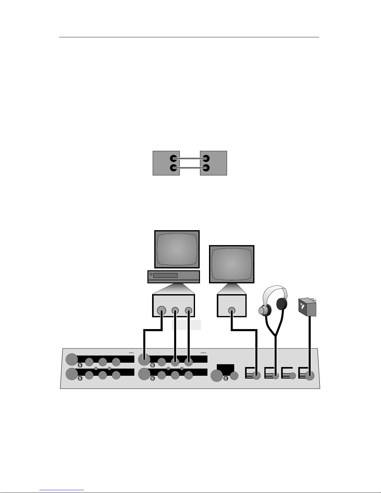
■ Connect the power supply (F) to the POWER input and plug it into a
working power outlet. Be sure to use the power supply that came with the
Mixer. Others, including the ones supplied with other Videonics products, may
damage the unit and void the warranty.
Move the POWER switch on the front panel to the ON (up) position and
the light above the switch will come on.
Page 19

PAGE 14 VIDEONICS DIGITAL VIDEO MIXER
■ Connect the OUTPUT monitor to the MX-1 OUTPUT jacks:
• If you will be recording the Mixer’s output (as in a video production
setup), connect the MX-1 video OUT to the VIDEO IN of the Record VCR
(B). Then connect a television or monitor to the Record VCR (A), as
described in the manual that came with the VCR.
You can use either S-video (Y/C) or composite (RCA-style) cables to
connect the MX-1 to the VCR. You can use S-video, composite, or RF
(cable/antenna) cables to connect the VCR and the television/monitor.
Connect the MX-1 audio OUT (marked L and R) to the Record VCR’s
AUDIO IN (C).
• If you will not be recording the Mixer’s output, connect the MX-1 video
OUT to the VIDEO IN of a monitor. You can use S-video (Y/C) or compos-
ite (RCA-style) cables for this connection. If you are using a television with
no VIDEO input (that is, it has only an RF (cable/antenna) jack, you will
need a VCR or an “RF modulator” to connect the MX-1 to it.
Connect the MX-1 audio OUT (marked L and R) to the monitor’s AUDIO
IN or to an external amplifier and speakers.
■ Set the OUTPUT monitor’s input switch.
If the television/monitor you are using has an input selection switch, set it
so it is displaying the correct input. For instance, if you have connected to
the monitor’s VIDEO 1 input jack, you would choose VIDEO 1 as your
input. Refer to the manual that came with your monitor for details.
■ Set the Record VCR input.
This step is important. Set the VCR’s controls so that it will record what-
ever comes into its VIDEO IN jack, rather than recording a broadcast
channel. Different VCRs use different methods to do this. Your VCR’s
manual should explain how, probably in a section that discusses copying
tapes from a camcorder. Here are some common examples:
• Most VCRs have an input selector switch that goes between LINE (or AUX,
EXT, A/V, or S) and TUNER:
CAMERA
EXT
TUNER
AUDIO 2
TV / LINE
S-VHS TUNER
INPUT SELECT
LINEAUX TUNERSC
SOURCE SELECT
Set the switch to LINE. Some VCRs have more than one VIDEO IN jack
(perhaps one is S-video and one is composite). Set the switch to match the
jack you are using to connect to the MX-1.
• Some use a button on the remote control or an on-screen menu to choose
an external line source.
Page 20
VIDEONICS DIGITAL VIDEO MIXER PAGE 15
• Others require that you choose a special channel (like 99 or A1).
• Still others switch automatically when you plug the cable into the VIDEO
IN jack.
■ Check the connections.
Turn the MX-1, VCR, and television on and press DEMO. You should see a
series of images with various transitions between them. Press DEMO
again to stop the demo.
■ Connect the PREVIEW monitor.
Connect the MX-1’s PREVIEW OUT to the VIDEO IN jack of the PREVIEW
monitor (D) using a composite (RCA-style) cable. (If the monitor only has
an RF (cable/antenna) jack, you will need a spare VCR or an RF modulator
to convert the RCA-style output to RF.)
■ Test the PREVIEW connection.
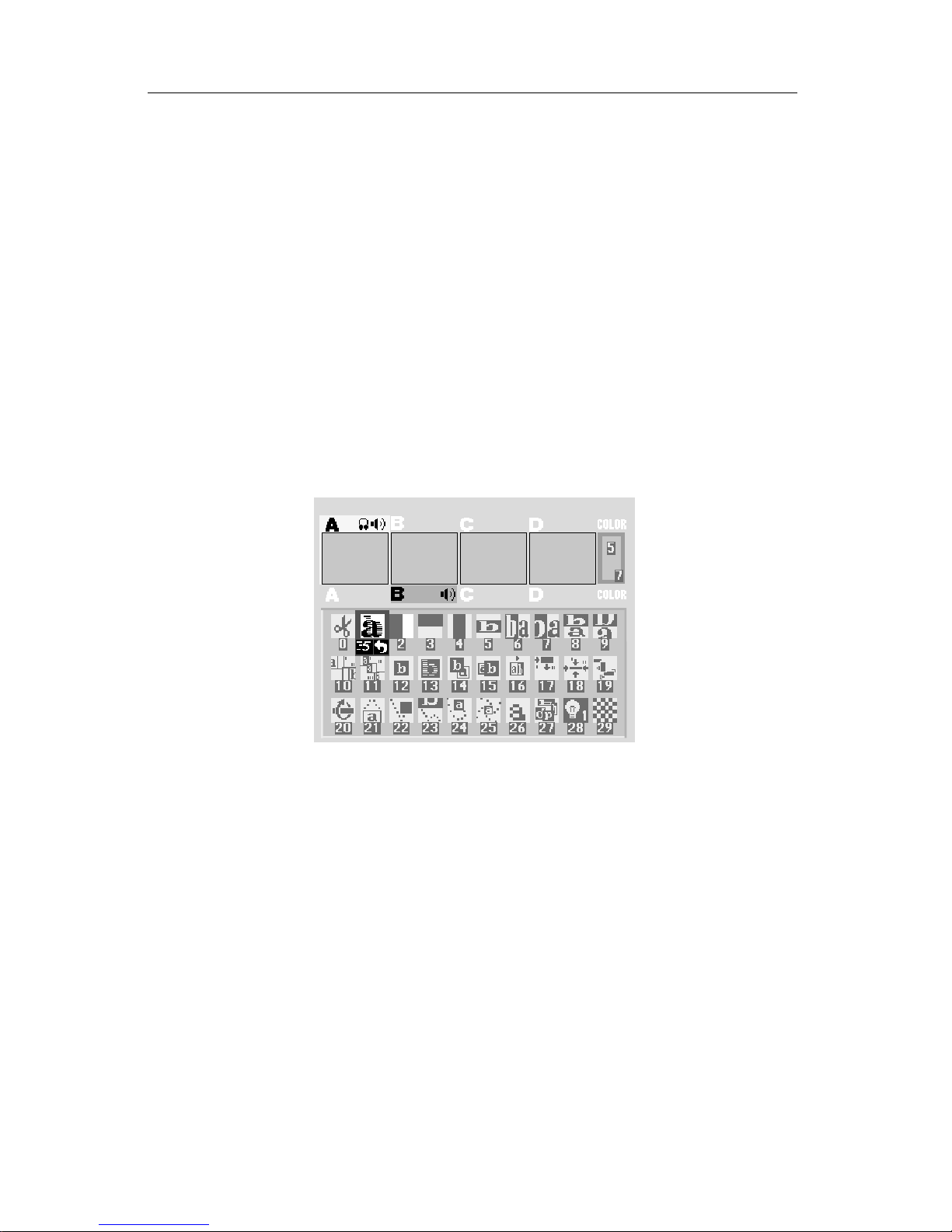
Turn the PREVIEW monitor on. You should see the PREVIEW screen:
■ Connect headphones.
If you wish to use headphones, connect them to the HEADPHONE jack
(E). The headphone jack accepts standard stereo headphones with a min-
iature plug, but the output is monaural (a mix of right and left channels),
not stereo.
■ CONTROL (GPI).
The CONTROL (GPI) input allows the Mixer to be triggered by GPI-
equipped edit controllers. It is described in Chapter 19, “Editing and Other
Applications.”
Connecting Sources
Video sources include camcorders, VCRs, laserdisc players, cameras, satellite tuners, broadcast tuners/receivers, video-equipped computers, etc. They
may have S-video (Y/C) or composite (RCA-style) output jacks. RF sources
(cable TV, antenna, “channel 3/4,” or other modulated sources) must be
Page 21
PAGE 16 VIDEONICS DIGITAL VIDEO MIXER
converted to S-video or RCA-style format video using a tuner, television,
VCR, etc.
You can mix input types, using S connections for some sources and RCA
for others. When you have both, S is preferred.
■ Connect each video source’s VIDEO OUT jack to the appropriate video IN
jack on the Mixer. Be sure to note which source is connected to which input
(IN 1 through IN 4).
IN 4
IN 1
IN 2
OUT
IN 3
V — IN 4 — S RLV S RLV S
IN 3
OUT
IN 2
IN 1
V
LRV
LRVLRV
LRV
K
J
G
HM
LN
I
VIDEO
OUT
AUDIO
OUT
VIDEO
OUT
AUDIO
OUT
VIDEO
OUT
AUDIO
OUT
VIDEO
OUT
AUDIO
OUT
VCR 1
VCR 2 VCR 3
Example Input Connections
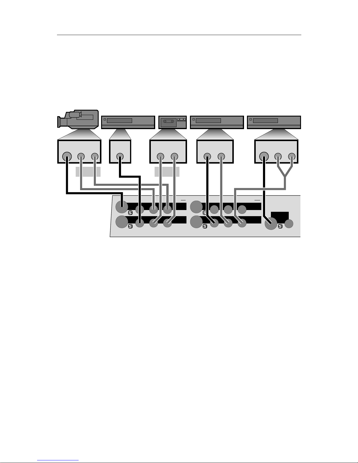
In the example above, a camcorder is connected to IN 1 (G) and VCRs are
connected to each of the other three inputs (I, K, L).
The camcorder and the last VCR are connected to S-video inputs (G and
L). The others (I and K) are connected to composite (RCA-style) jacks.
■ Disable processing circuits.
Some VCRs have circuitry that is intended to improve the apparent sharp-
ness of their outputs. These circuits often boost the signal past standard
limits and can interfere with the MX-1’s TBC (time base corrector). We
recommend you turn such options off.
The most common processing control is the EDIT switch. This switch
should be set to the ON position (which disables processing). Another
common control is SHARPNESS which should be set to zero or off.
■ Connect the audio inputs.
Connect each audio source’s AUDIO OUT jack to the appropriate audio
IN jack on the Mixer. Audio can come from audio devices, such as tape
and CD players, as well as from VCRs and camcorders.
Usually, the sound from each VCR or camcorder will be connected along-
side the video connection, the way the camcorder is connected in the
Page 22
VIDEONICS DIGITAL VIDEO MIXER PAGE 17
preceding diagram (G, H). But many other arrangements are possible. The
diagram gives some examples:
• VCR 1’s audio output is not used (I). Only its video is connected, to IN 2.
• A tape player is connected to IN 2’s audio inputs (J).
• VCR 2 has mono sound, connected to IN 3’s left input (M). VCR 3’s stereo
audio is converted to mono using a Y-cable (N) and is connected to IN 3’s
right channel.
IN 3’s audio can be “split” — sent to two different sources, so that the left
input would appear as source C, for instance, and the right input would
appear as source D. See Chapter 5, “Setup Screen,” for details on splitting
IN 3’s audio.
■ Input monitors (optional).
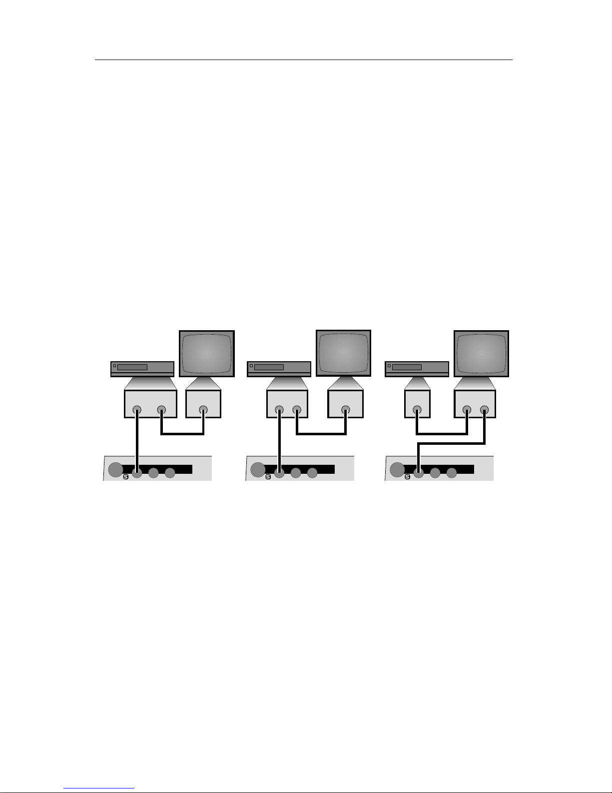
You can add a monitor to each input if you would like a full screen view of
each source. There are three ways to connect an input monitor, depending
on what type of jacks are on your VCRs and monitors:
IN 1IN 1 IN 1
LRVLRV LRV
❸❷❶
VIDEO
OUT
VIDEO
IN
VIDEO
OUT
VIDEO
OUT
VIDEO
OUT
ANTENNA
IN
ANTENNA
OUT
VIDEOINVIDEO
OUT
Three Ways to Add a Monitor to an Input
∂ Most VCRs are equipped with an ANTENNA or RF or VHF or CABLE TV
output, in addition to the VIDEO OUT. You can use that output to connect
to a television’s ANTENNA/CABLE TV input.
∑ Some VCRs have two VIDEO OUT jacks. One can be connected to the
Mixer and the second can be wired to the monitor.
∏ Some monitors have an output as well as an input, allowing the signal to
pass through the monitor to the Mixer.
■ Test the input connections.
When the MX-1 is turned on, it automatically sets up IN 1 to be source A,
IN 2 to be source B, etc. If the Setup screen has not been used to change
these, you should be able to press the CUT buttons and see the sources you
have connected. Press CUT→A and the OUTPUT monitor should show
whatever is plugged into IN 1. Press the rest of the CUT buttons and you
should see the other inputs on the OUTPUT monitor.
Page 23

PAGE 18 VIDEONICS DIGITAL VIDEO MIXER
Note: If the picture tears or you see horizontal white or black lines, see
Chapter 20, “Video Quality.”
Page 24
VIDEONICS DIGITAL VIDEO MIXER PAGE 19
Chapter 4 •Chapter 4 •
Connecting Editing Equipment
The Mixer is compatible with a wide range of editing equipment,
such as edit controllers, title generators, video processors, and audio
mixers. It can be connected in a variety of ways, depending on what
you plan to do and what equipment you have.
This chapter describes how to connect editing equipment. For information
on the use of editing equipment, see Chapter 19, “Editing and Other Applications.”
Hint: Verify that the basic connections, described in the previous chapter, are
working properly before you add advanced equipment.
Processing the Inputs vs. the Output
DIGITAL VIDEO MIXER
VIDEONICS
DIGITAL VIDEO MIXER
VIDEONICS
❷❶
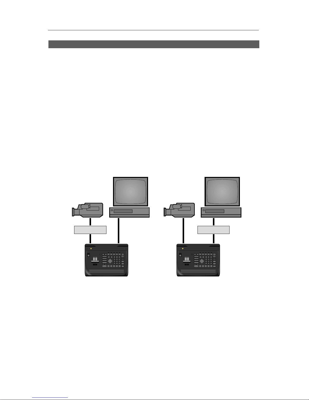
Video processors, color correctors, enhancers, and the like can be used
between any source and the MX-1 (∂ ); or they can be placed between the MX1’s output and the recording VCR (∑).
• If different sources need different kinds of correction, then a processor
should be connected between the output of each source and the Mixer
input (∂ ).
• If everything needs to be processed in the same way, then you can place
one processor at the output (∑). Connecting a processor at the Mixer’s
output will adjust the overall signal. This requires only one processor but
cannot make independent corrections to each source.
Hint: Note that the Mixer’s built-in TBC insures that the time base of its output
will match broadcast time base standards. A video processor may or may not meet
similar standards. Adding a processor prior to the Mixer’s inputs is less likely to
Page 25
PAGE 20 VIDEONICS DIGITAL VIDEO MIXER
degrade the time base than adding one to the Mixer’s output, since degradation at the
input is likely to be corrected by the Mixer’s TBC.
Adding Titles
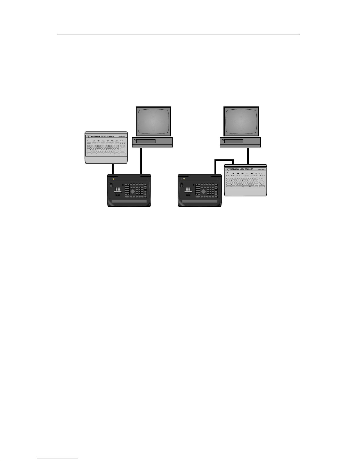
As with video processors, you can connect a titler to an input, an output,
or both.
DIGITAL VIDEO MIXER
VIDEONICS
DIGITAL VIDEO MIXER
VIDEONICS
A
A
A
A
A
A
❹
❸
• When connected to an input (∏ ), you can use the titles as is, using
transitions to go from a video source to a screen of titles. You can superim-
pose titles on a source by using the Mixer’s chroma key function.
• If you have a titler that is capable of doing its own superimposing, you can
use it between the output and the Record VCR (π ). This arrangement has
an important advantage: titles can be superimposed over the mixed signal.
For instance, you could have a wipe from B to C and have titles superim-
posed over the entire transition, rather than just having the titles atop
either B or C.
Hint: Connecting the titler to the output is the most flexible arrangement as long
as the titler is of high quality and doesn’t degrade the output signal. Titlers of lesser
quality should probably be used only on the inputs.
Audio Mixing
The MX-1 includes basic audio mixing. The sound can follow video transitions or can come from an independent source.
If you need more flexibility, you can connect an external audio mixer to
any of the audio inputs. You can also bypass the MX-1 entirely, connecting
the audio mixer’s output directly to the recorder’s audio input.
The advantage of using the MX-1’s audio mixer is that it can simultaneously fade the sound and picture. An external mixer requires that you do
this manually.
Page 26

VIDEONICS DIGITAL VIDEO MIXER PAGE 21
Edit Control
An external edit controller can be used to control the source and Record
VCRs. Mixer transitions can be triggered at the critical moment by a “GPI
trigger,” if the controller has a GPI output and it is connected to the Mixer’s
CONTROL input.
See Chapter 19, “Editing and Other Applications,” for more information.
Page 27

PAGE 22 VIDEONICS DIGITAL VIDEO MIXER
Chapter 5 •Chapter 5 • Setup Screen
The Setup screen allows you to change how the inputs and outputs are used and define certain options. You can:
• Route any video input jack (IN 1, 2, 3, 4) to source A, B, C, or D.
• Decide whether to use the S-video or composite (RCA-style) video
jacks.
• Route the audio inputs to source A, B, C, or D.
• Split IN 3’s audio inputs to feed two mono channels.
• Select advanced setup options.
Defaults
Hint: Most users will not need to modify anything in the Setup screen. When you
first turn the Mixer on, the default factory settings automatically establish the most
common settings:
• IN 1’s video and stereo audio appear as source A.
• IN 2’s video and stereo audio appear as source B.
• IN 3’s video and stereo audio appear as source C.
• IN 4’s video appears as source D, with no audio.
Note that these factory settings are restored whenever you turn the Mixer
on.
Automatic Connection
The fastest way to reach the correct setup is via the automatic connection
feature.
Connect all your sources, turn them all on, and make sure they are playing
a video signal of some kind (such as a videotape or broadcast video). Press
the SHIFT and AUDIO/VIDEO buttons at the same time (or turn the unit off
then on again) and the unit will look at the inputs and determine which ones
are carrying signals. For each of the four inputs, it will automatically use the
jacks that are carrying signals:
• If an input has a signal on both the S-video and the composite (RCA-style)
jacks, the S-video jack will be used.
• If an input has a signal on only one of the jacks, that one will be used.
Any video signal, including a blank screen or on-screen display, will be
detected. Inputs are monitored continuously, so you can change the connections, until the Setup screen is used. Once the Setup screen appears, the
Page 28
VIDEONICS DIGITAL VIDEO MIXER PAGE 23
automatic connections are locked in and can only be changed manually,
using the Setup screen.
Audio connections are not changed by the automatic connection feature.
Routing the Inputs
If the automatic connections are not satisfactory, you can change the input
routing using the Setup screen. The most common reasons for doing this are:
• You want to make one video signal appear on two sources, so you can do
transitions from a signal to a modified version of the signal (example:
dissolve from A to posterized A).
• You want to split the IN 3 audio input. (IN 3 is special: you can make one
of the IN 3 audio jacks feed C and the other feed D, both in mono.)
• You are connecting to both the composite and S-video jacks of one input
but want to use the composite (normally, the S-input is used if something
is connected to it).
The Setup Screen
Press the SETUP button to see the Setup screen:
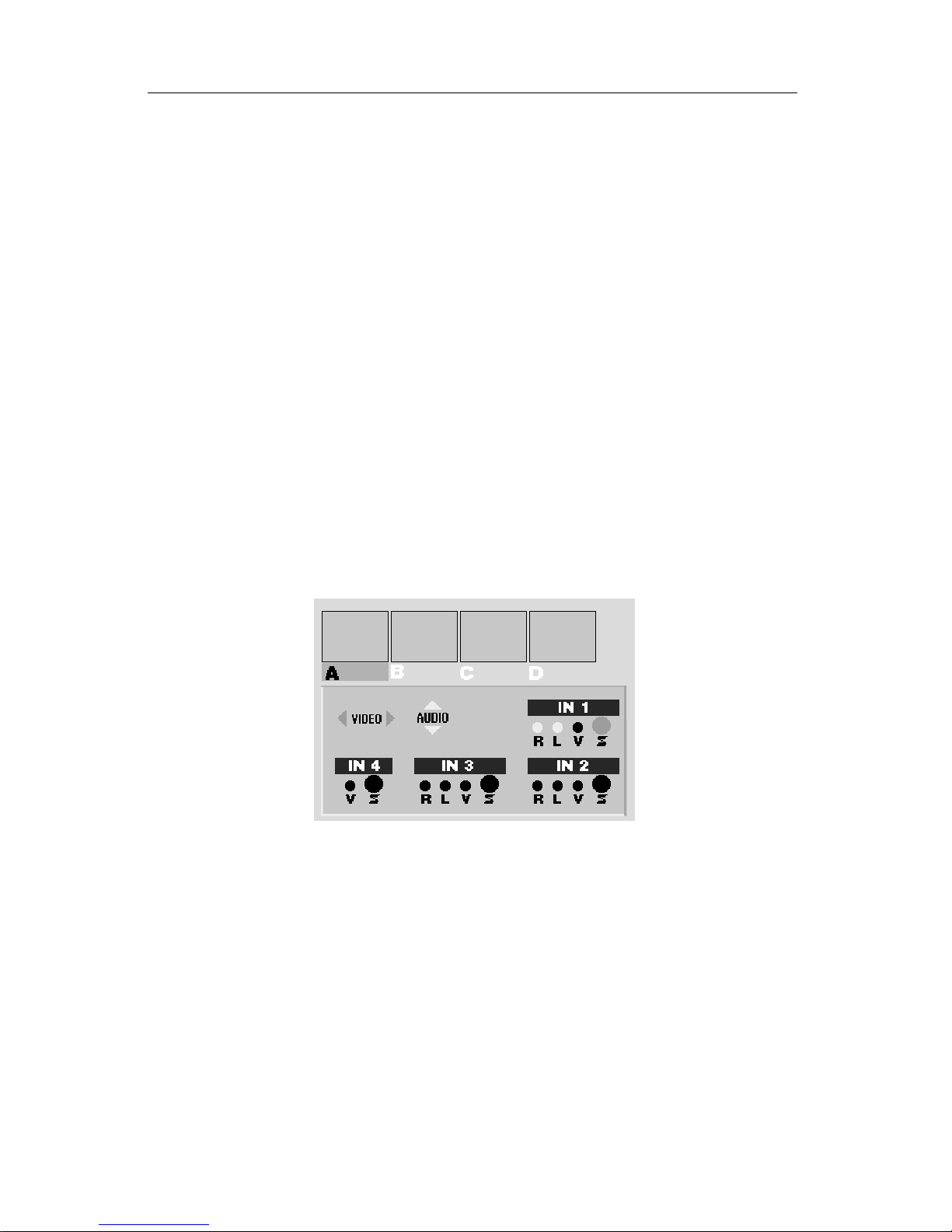
The screen shows sources A, B, C, and D. Beneath the sources is a representation of the Mixer’s back panel. The on-screen diagram is oriented as it
would appear from the front of the unit. (This makes it easy to identify how
your cables are connected without turning the unit around.)
One of the sources (A, B, C, or D) is highlighted in green. The diagram
shows which inputs feed the highlighted source. For example, in the illustration above, source A is highlighted. The highlighted features in the diagram
tell you IN 1’s S-video input is connected to source A and the stereo audio
jacks (L and R) for IN 1 are also connected to A.
To make changes:
• Use the ABCD buttons at the bottom of the Mixer’s panel (not the CUT
buttons) to choose the source you want to change. The highlight will
change to indicate which source is being set up and the connection draw-
ing will show the current settings for that source.
Page 29
PAGE 24 VIDEONICS DIGITAL VIDEO MIXER
• Use the right and left arrow keys to change the video connection. You can
choose either the S-video (Y/C) jacks or the composite (RCA-style) jacks of
any of the four inputs.
• Use the up and down arrows to change the audio connection. You can use
the stereo audio jacks (both L and R) from IN 1 or IN 2 or IN 3, or you can
choose the L-only jack from IN 3, or the R-only jack from IN 3. If you use L-
only or R-only from IN 3, then whatever appears on that jack will be
routed to both the left and right channels. A mono source can be connected
in this way and its sound will appear on both channels.
You can also choose no audio at all, making that source silent. To do this,
press the up arrow button until none of the audio inputs are highlighted.
• Press OK or SETUP to return to the PREVIEW screen when you’re done.
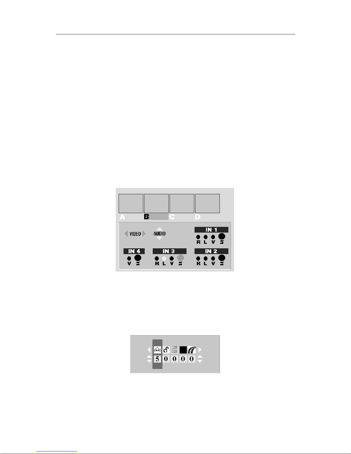
For example, if you wanted source B’s video to come from IN 3 and you
wanted B’s audio to come from the left jack of IN 3, you would press B to
highlight the B source, then use the up and down arrow keys to make the
screen look like this:
Note that any changes you make to the Setup screen are lost when the unit
is turned off or loses power.
Advanced Setup
Press the SHIFT and SETUP buttons simultaneously to alter the advanced
settings.
Hint: Most users will have no need to alter these settings, with the exception of
headphone volume or the use of filter settings when working with sources of marginal
quality.
• Use the right and left arrow keys to choose the setting you want to change.
Page 30

VIDEONICS DIGITAL VIDEO MIXER PAGE 25
• If you are changing the noise filter or chroma AGC settings, use the ABCD
buttons at the bottom of the Mixer’s panel to choose which source you
wish to change. (The other settings affect all sources at once and do not use
the ABCD selection.)
• Use the up and down arrow keys to make the change.
• Press OK or PLAY when you’re done.
Here are the options you can change and their meanings (from left to right
in the above diagram):
Headphone Volume: 0 is the lowest setting and 9 is the highest. Headphone volume is the same for all sources — the ABCD buttons have no effect
when you are setting headphone volume.
Input/Output Frame Rate Lock Disable: This setting (explained in detail
in Chapter 18, “TBC”) compensates for slight deviations in video frame rate
between the inputs and the output. When it is locked (setting 0), the MX-1
adjusts the frame rate of the output by very small amounts at the end of each
video field, to reduce or eliminate the need to repeat or drop video fields.
This is the normal setting and is appropriate for most equipment.
The ABCD buttons have no effect on Frame Rate Lock Disable — it affects
all sources at once.
Noise Filter: The MX-1 includes a very sophisticated filter which adjusts
the appearance of the video. The normal setting, 0, passes the full, maximum
quality signal through and is the best setting for most equipment. Higher
settings increase filtering to compensate for video signal problems such as
video that is over-processed using sharpness controls, enhancers, etc. Use the
higher settings if you see picture lines shift to the right, horizontal white
flashes, horizontal black lines at the left hand edge of the picture, or shredded
pictures. Chapter 20, “Video Quality,” discusses this in detail. Increase the
setting until the problem is alleviated.
These settings can also be used to reduce noisy (snowy) video. Some
settings affect the whole picture and some only affect edges of shapes and
lines.
Each source has its own noise filter setting, so you can adjust each separately. Note that these settings go back to 0 when the power is lost.
Black Level: Video equipment commonly uses one of two black level
settings: 7.5 IRE units, the traditional black, and 0 IRE, a darker black level
favored by a variety of modern equipment. When this setting is 0, the Mixer’s
background and border colors use the extra dark black (0 IRE) level. Change
the setting to 1 if you are working with equipment that requires 7.5 IRE.
Composite Chroma AGC: If a composite (RCA-style) input source has a
weak color signal, the Mixer can be set to compensate. If a composite source
looks pale, set the Composite Chroma AGC setting to 1 and the AGC (Automatic Gain Control) will automatically adjust color levels on all composite
inputs. Most sources have correct chroma levels and we recommend you
leave this setting at 0. AGC does not affect S-video sources.
You can adjust chroma AGC for each composite (RCA-style) source. Note
that if the Setup screen shows that a source is set to use the S-video (Y/C)
jack, the AGC setting will not change.
Page 31

PAGE 26 VIDEONICS DIGITAL VIDEO MIXER
Seeing the Settings
The small preview screens do not show the effects of these settings. To see
the full screen picture as you change the settings, set both CURRENT and
NEXT to the source you are adjusting before you display the advanced setup
screen. You will see the effect on the OUTPUT monitor as you make adjustments. You can also see the effects on the PREVIEW monitor, without disturbing the output, by pressing the DISPLAY button. (These techniques are
described in more detail in Chapter 11, “Input Effects,” under the heading,
“Seeing the Settings.”)
Page 32
VIDEONICS DIGITAL VIDEO MIXER PAGE 27
Chapter 6 •Chapter 6 • Basic Controls
The Mixer is controlled through its front panel and the on-screen
controls of its PREVIEW screen. This section describes the basics.
Built-In Demo
The Mixer includes a built-in demo that shows many of the transitions.
Simply press the DEMO button and the unit will cycle through many of its
transition effects. To exit the demo, press any key.
You can also start the demo by pressing SHIFT and DEMO at once. When
started this way, only the DEMO button will stop the demo. (The purpose of
this is to prevent passers-by from accidentally stopping the demo).
If two or more video sources are connected to the Mixer, the demo uses the
first two sources it finds and runs transitions from one source to the other and
back. If just one source is connected, the Mixer will generate transitions from
the source to itself.
The PREVIEW Screen
❶
❷
❸
❹
❺
❺
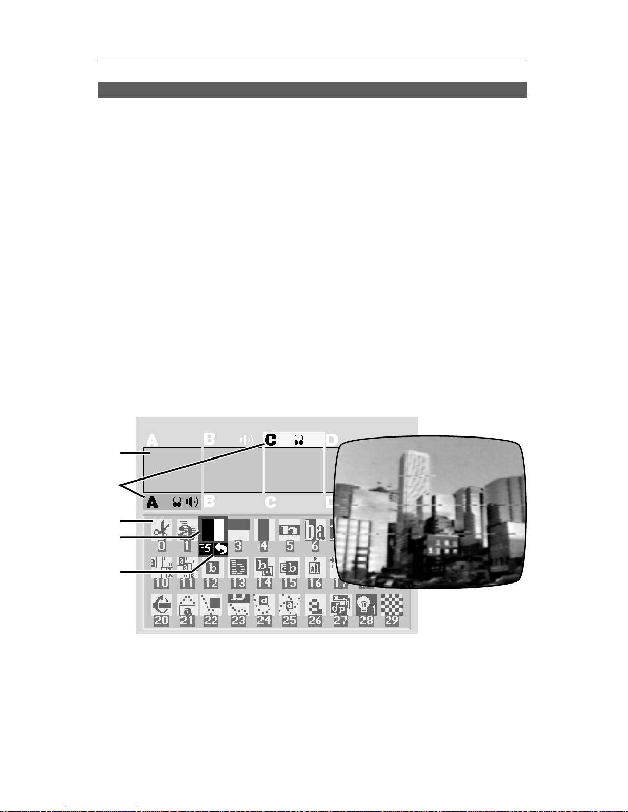
The PREVIEW screen is the heart of
Mixer operation. It contains:
∂ Preview images of the four sources
∑ Highlights that identify which sources are active
∏ A “palette” of symbols used to choose transition effects
π A blue highlight which indicates the selected transition
∫ Controls for speed, direction, background color, and border color
Marginal video source quality
can cause lines, tears, and
other problems in the video
Page 33

PAGE 28 VIDEONICS DIGITAL VIDEO MIXER
Source Previews
All four sources appear on the PREVIEW screen, in miniature (∂ ). You can
use the previews to watch the action, position cameras, find a spot on a tape,
etc.
Preview Image Quality
The miniature previews are designed for a quick, convenient view of all
the action and won’t match the quality of the video that appears on the
Mixer’s normal output. The size and “frame rate” of the images are reduced
and there may be occasional lines appearing alongside the preview images.
They do not show input effects or the results of Advanced Setup settings.
The appearance of the preview images does not affect the Mixer’s output.
During transitions, the PREVIEW screen is automatically replaced by a
full-screen image at full frame rate.
Note that when there is something critical you want to see on one of the
sources, you can switch to full screen, full quality display using the DISPLAY
button, as described in the section, “Switching the DISPLAY,” in this chapter.
CURRENT and NEXT Source Selection
The Mixer uses four input sources, labeled A, B, C, and D. (There’s also a
fifth source, the Mixer’s own background color generator.) All transitions
start with one source, called the CURRENT source, and end with another,
called the NEXT source. Colored rectangles, or highlights, (∑) indicate these
sources.
The yellow highlight above the previews indicates the CURRENT source
and the green highlight, below the previews, indicates the NEXT source. The
CURRENT and NEXT sources for sound are indicated by the sound symbols
in the highlight areas.
CUT ➔
ABCD
COLOR
CUT ➔ CUT ➔ CUT ➔ CUT ➔
In addition, lights on the front panel, above the CUT buttons, tell you
which video sources are selected. A steady light identifies the CURRENT
source and a flashing light identifies the NEXT source.
The CURRENT and NEXT sources change when you perform an effect or
when you use the ABCD or CUT buttons, as explained in the next few
chapters.
Transition Controls
Below the previews is an array of symbols (∏). Each symbol represents a
transition effect. A blue highlight (π ) shows which effect will be used for the
Page 34

VIDEONICS DIGITAL VIDEO MIXER PAGE 29
next transition. Other on-screen controls (∫ ) indicate the next effect’s speed
and direction and the colors of the background and border.
The following chapters explain these items.
Viewing a Transition
While a transition is being performed, the PREVIEW display disappears
and is replaced by the transition effect, performed at full quality and frame
rate. When the transition ends, the PREVIEW display returns. This gives you
full screen display of all effects on both the PREVIEW and OUTPUT monitors.
Switching the Display
You can change what appears on the PREVIEW monitor, using the DISPLAY button. Each time you press DISPLAY, the PREVIEW monitor will
switch between these three possibilities:
• Normal PREVIEW screen with the miniature preview images and on-
screen controls.
• Full frame rate, full quality view of the NEXT source (the source which
will be displayed on the OUTPUT after the next transition is performed).
• Full frame rate, full quality view of the CURRENT source (the source
which is currently being displayed on the OUTPUT).
The OUTPUT monitor always displays the CURRENT source except during a transition, when the transition is displayed.
Video Quality
The Mixer automatically maximizes output quality when quality video
sources are used. When working with marginal sources, bad reception, or
videotapes with sharpness or other processing circuits on, the output may
show horizontal white or black lines or shredded video.
If you encounter these symptoms:
• Use quality video sources.
• If you are using a VCR or camcorder with an EDIT switch, turn it ON to
disable playback processing circuits.
• Turn off sharpness controls and enhancement circuits.
• Change the noise filter settings described in the “Advanced Setup” section
of Chapter 5.
Page 35

PAGE 30 VIDEONICS DIGITAL VIDEO MIXER
Chapter 8 •Chapter 8 • Transitions
The MX-1 Video Mixer includes hundreds of transitions that can
be used to go from one source to another. They range from simple
cuts, dissolves, and wipes to sophisticated zooms, fly-ins, and flips.
Transitions can be executed automatically, at any of ten speeds, or
manually, using the T-bar control.
The Basic Concept
To make a transition from one source to another:
• Start with the CURRENT source. This is the one that is presently on the
OUTPUT screen.
• Choose the NEXT source — the one that will be on the OUTPUT screen
after the transition is complete.
• Choose the desired transition effect.
• Prepare your playback devices (such as VCRs and camcorders) and let
them roll. At the right moment, execute the effect, using the “T-bar” or the
PLAY button.
The key concept is that first you set the transition up, then you execute it.
Nothing happens until you use the PLAY button or T-bar.
You can select the CURRENT source, the NEXT source, and the effect in
any order. You can change them as much as you like before you execute the
effect.
Page 36
VIDEONICS DIGITAL VIDEO MIXER PAGE 31
At the completion of the effect, the NEXT source becomes the CURRENT
source and you are ready to select the new NEXT source and effect for
another transition.
Which Source is Which?
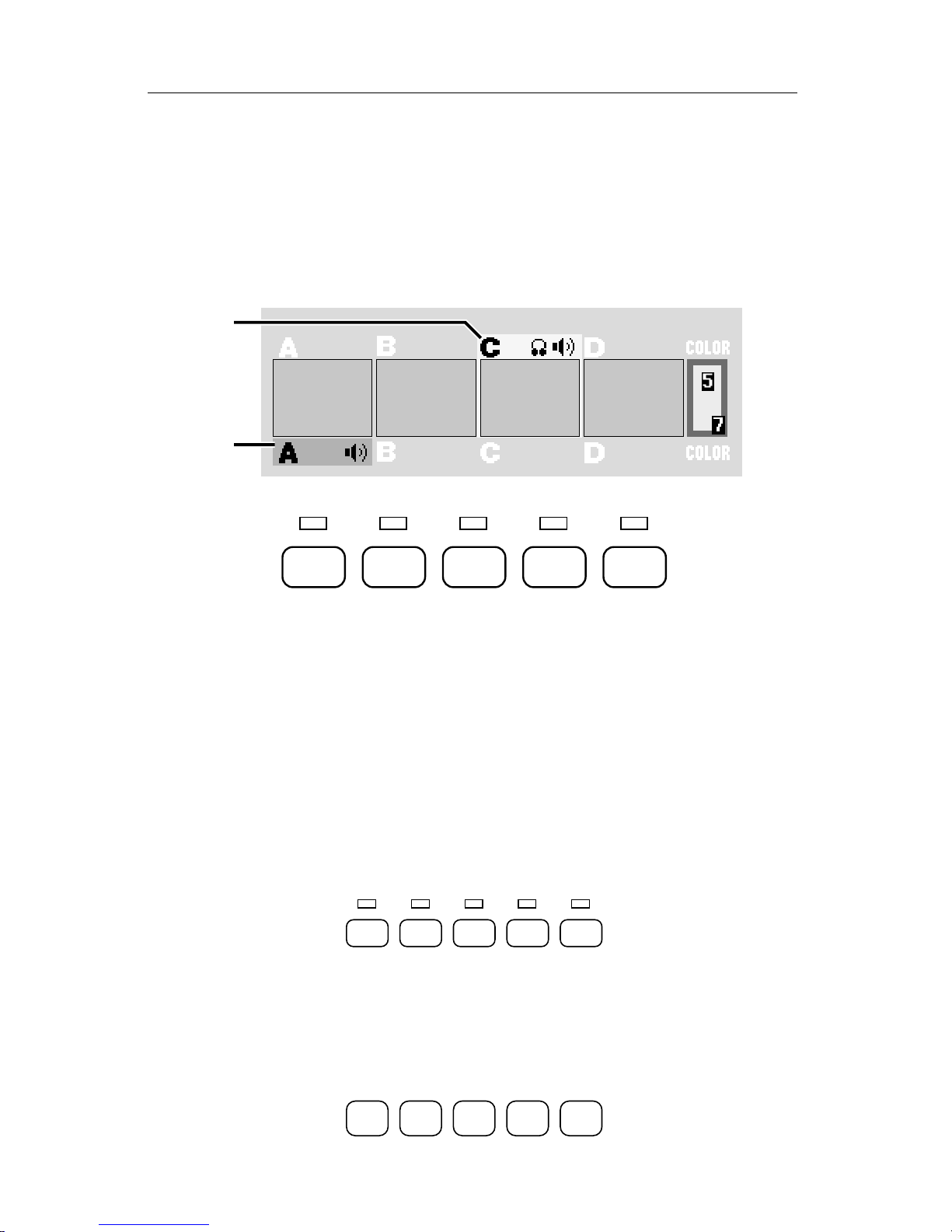
The lights above the CUT buttons and the highlights on the PREVIEW
screen indicate the CURRENT and NEXT sources.
A
B
CUT ➔
ABCD
COLOR
CUT ➔ CUT ➔ CUT ➔ CUT ➔
A The CURRENT source is always indicated by the yellow highlight on the
PREVIEW screen and the steady light above the appropriate CUT button.
B The NEXT source is indicated by the green highlight and by the flashing
light.
If NEXT and CURRENT are set to the same source, the source’s light
flashes as if it were just the NEXT source.
Changing the CURRENT Source
Most of the time, you won’t need to change the CURRENT source (because
the ending source of the previous transition automatically becomes the new
CURRENT source).
CUT ➔
ABCD
COLOR
CUT ➔ CUT ➔ CUT ➔ CUT ➔
If you do wish to change the CURRENT source, press the appropriate CUT
button. For instance, CUT→C will make C the CURRENT source and the
OUTPUT monitor will immediately show source C’s video.
Choosing the NEXT Source
ABCD
COLOR
Page 37
PAGE 32 VIDEONICS DIGITAL VIDEO MIXER
To choose the NEXT source, use the ABCD buttons at the bottom of the
control panel.
Choosing the Transition Effect
D
C
E
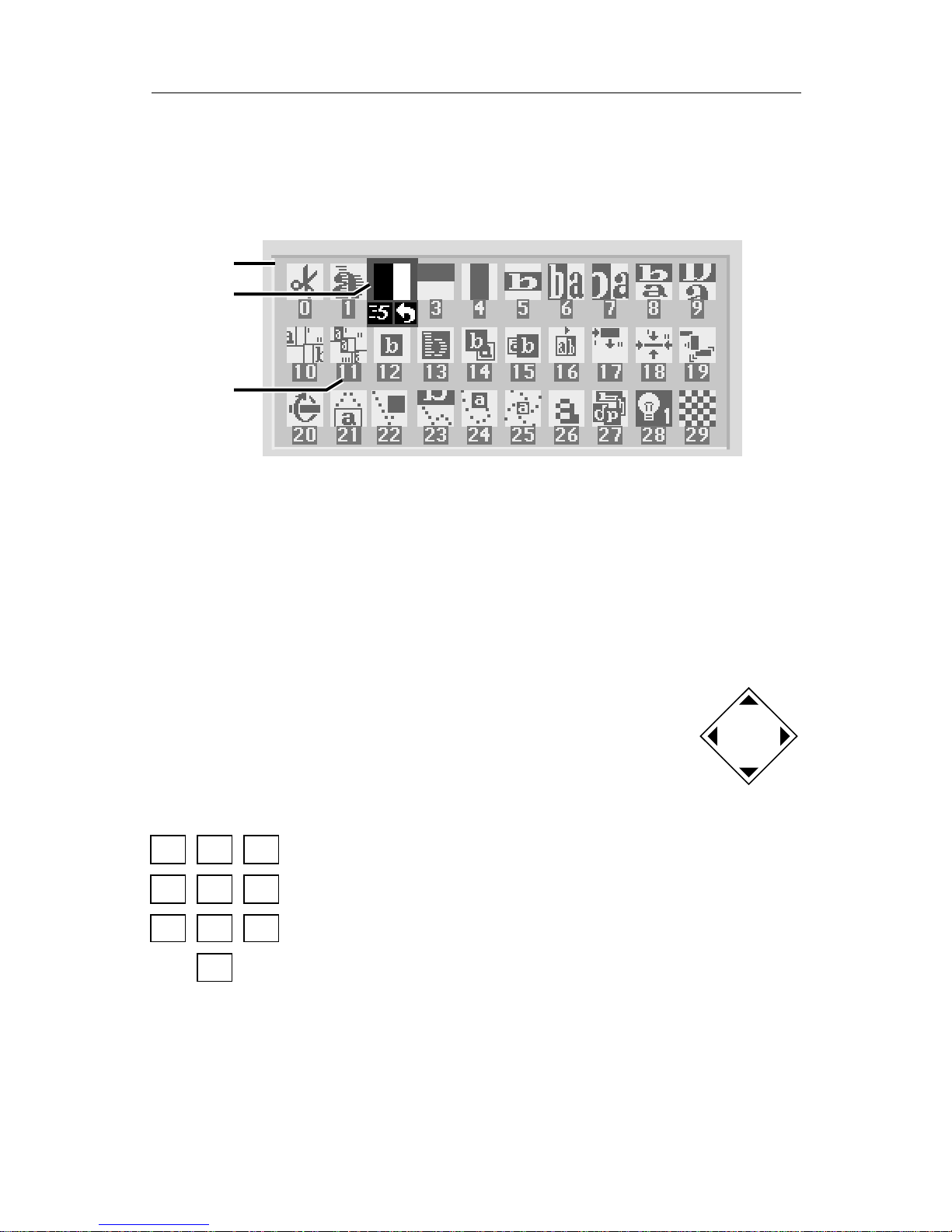
Below the preview images is an array of symbols (C). Each symbol represents one of the available effects. A blue highlight (D) shows which effect has
been selected.
The “Top 30” Effects
There are over 200 different effects available. However, note that the first
30 symbols (the ones that appear on the screen when you first turn the unit
on) represent commonly used effects and these may be all you need.
Hint: To quickly move to the top 30 effect symbols, press 0 and
OK.
Ways to Choose Effects
There are three ways to choose an effect:
1. The arrow keys
Use the arrow keys to move around the transition effect
palette. The blue highlight moves to the next symbol, in the
appropriate direction.
2. The number keys.
Every effect has a number (E), shown below the effect’s
symbol. As you use the Mixer, you will begin to learn the
numbers of the effects you use most. The numbers give
you a very fast and convenient way to select effects. Simply
enter the number of the effect you want.
As you enter the number, the digits will appear inside the blue highlight
box. Press OK and the effect corresponding to that number will be highlighted.
Hint: You do not need to press OK and you do not need to wait for the symbol to
be highlighted — simply press the digits and immediately PLAY to perform the
effect.
7
4
0
859
6
123
Page 38
VIDEONICS DIGITAL VIDEO MIXER PAGE 33
If you make a mistake while entering a number, simply press any arrow
key or OK to end the number you were entering, then enter
the correct number.
A list of effects is in the back of this manual and on the
Reference Card.
3. The large transition effect buttons
The effects keys quickly locate the most common effects. Press WIPE, for instance, and the most common wipe
is instantly highlighted. Press ZOOM/P-IN-P to find a
flip/picture-in-picture effect.
Similar effects are grouped together. This means that
after you have used a large button to locate a family of effects, you can use the
arrow keys to find the variation you want. For example, WIPE takes you to
effect 30, a horizontally-moving wipe. Press the down arrow once to choose a
horizontally-moving curtain wipe (effect 40). Press DOWN three more times
to reach the vertically-moving wipes.
Executing the Transition
Once you have chosen the two sources and the effect, you can perform the
transition automatically or manually. Automatic operation has the advantage that it is smooth and repeatable. Manual transitions have the advantage
of control — you control the speed and you can make the effect speed up,
slow down, or even reverse itself in mid-effect.
Note: Depending on the relative timings of the input video signals, a thin
black stripe may separate the two images when you use an effect that includes a compress or slide. The width of the stripe may vary as you perform
an effect manually.
Note: If the strobe input effect is applied to one of the sources (Chapter 11),
it is turned off during the transition.
Automatic (AUTO-TAKE) Execution
To perform a transition automatically, at a predetermined speed, simply
press the PLAY (AUTO-TAKE) button.
You can interrupt (pause) an automatic transition by pressing PLAY again.
Each time you press PLAY, the transition starts or stops, until it finally is
allowed to complete. (Note that although the transition has paused,
the video continues to play. Contrast this to pressing FREEZE
which freezes the entire picture, transition, video images, and all.)
Changing the Speed
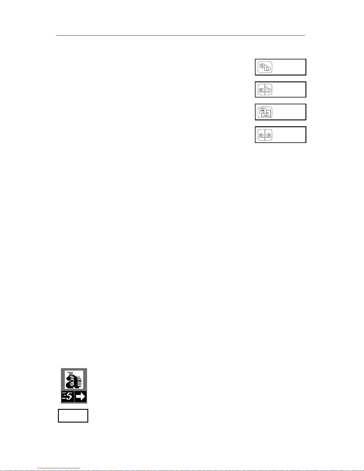
You can alter the speed of automatic execution. The current
speed appears below the transition effect’s symbol (in this case,
the speed is 5). 0 is the slowest speed, 9 is the fastest.
ZOOM /
P-IN-P
FLIP
WIPE
FADE /
DISSOLVE
SPEED
Page 39

PAGE 34 VIDEONICS DIGITAL VIDEO MIXER
To change the speed, press the SPEED button. The number will increase by
1 with each press. Continue pressing until the speed is set to the desired
number.
Hint: Press SHIFT and SPEED at the same time to decrease the number.
You can change the speed anytime before you execute the effect. The new
speed remains in effect for all future transitions, until you change the speed
again.
Advanced hint: You can also choose a speed by simultaneously pressing the
SPEED button and a number key, 0 through 9.
Manual Execution
Most of the time, you will probably use automatic transitions because they
are smooth and consistent. When you want to exercise additional control (or
you just want the satisfaction of doing it yourself), you can use the “T-bar” to
manually execute the transition. (The name “T-bar” is short for “Take-bar,”
and also because it’s shaped like a T).
The T-bar must be at one end of its swing or the other to begin the
transition. Nothing will happen until the bar is all the way up or all the way
down.
The direction of the T-bar’s motion does not matter: Moving it up from the
bottom or down from the top does the same thing.
Once a manual transition has started, you can move the T-bar back and
forth, making the transition move in and out. The effect ends once you reach
the end of the bar’s motion. Moving it from the end of its travel will begin a
new transition.
Setup for the Next Transition
When a transition has ended, the Mixer automatically swaps the CURRENT and the NEXT sources. That is, what had been the CURRENT source
becomes the NEXT source and what was the NEXT source becomes the
CURRENT source.
This makes it very easy to go back and forth between two sources: Simply
set up the first transition, then press PLAY (or move the T-bar) over and over.
The transition will alternate between the two sources.
Example: We wipe from A to C (A is the CURRENT source, C is the NEXT
source). At the end of the wipe, C (the ending source) automatically becomes
the CURRENT source and A automatically becomes the NEXT source. So,
simply pressing PLAY repeatedly will give you a wipe back and forth, from
A to C to A to C, etc.
Of course, you don’t have to alternate: The NEXT source and the effect can
be changed at any time, changing the results of the next transition.
Performing the Next Transition
At the end of each transition, the ending source is held on the screen for a
moment before the PREVIEW screen returns. You can start the next transition
Page 40
VIDEONICS DIGITAL VIDEO MIXER PAGE 35
or other action immediately — you do not need to wait for the PREVIEW
screen.
Reverse
A transition is often used to show a change to another point of
view or to another time or location. The same effect, moving in the
opposite direction, shows a return to the previous viewpoint, time,
or place.
For example: In a documentary about a famous violinist, a wipe
is used to transition from scenes of the musician on stage to old
footage of early appearances. The director wants a right-moving
wipe when going to the old scenes and a left-moving wipe when
returning to the present day. The reverse feature would be used to
accomplish this.
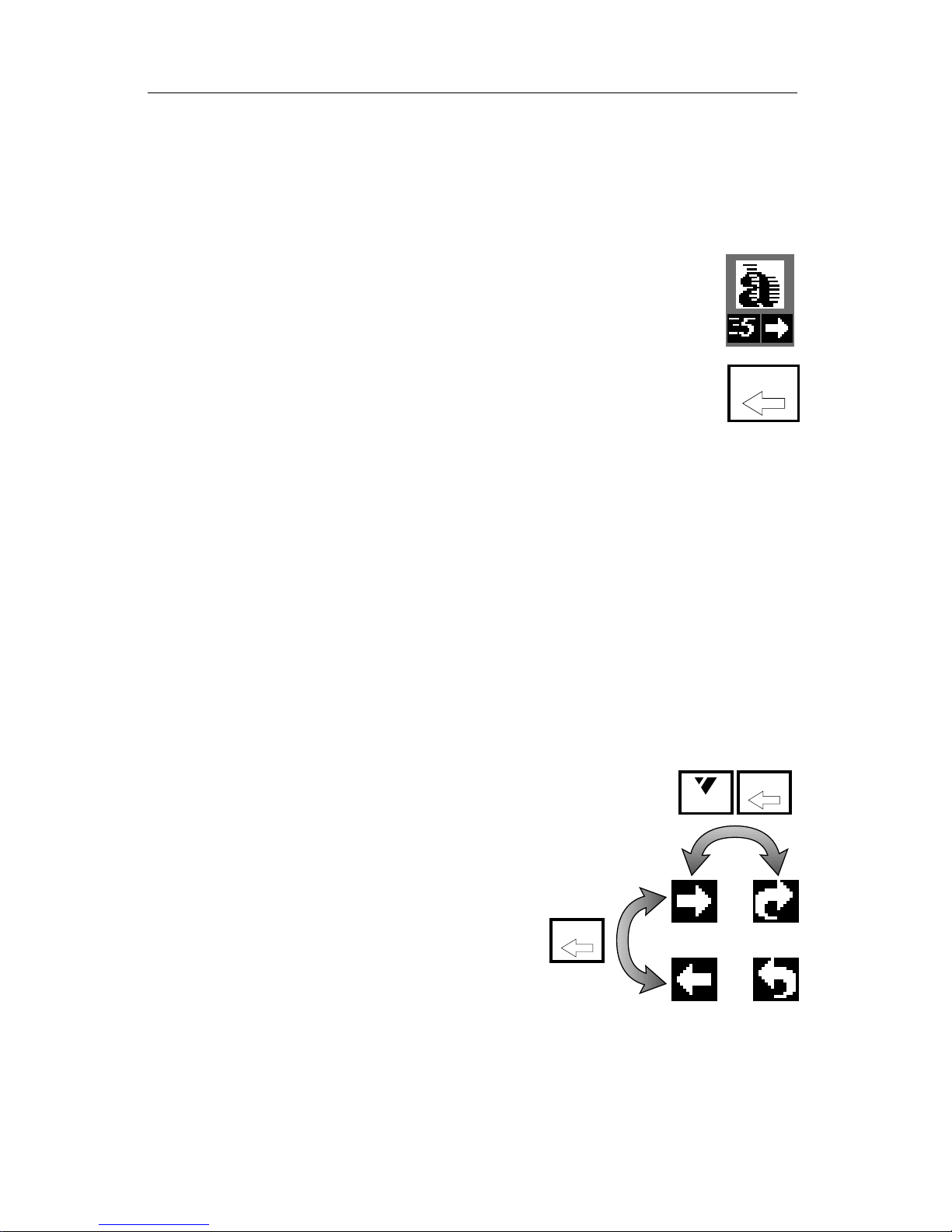
The REVERSE button changes the direction of effects. An arrow under the
highlighted effect’s symbol shows whether the effect is reversed. When the
arrow points to the right, the effects are set to the normal forward direction.
Reversed effects are indicated when the arrow points left.
Note that it is the direction of the effect’s motion that is reversed — the
sources are not changed. For instance, a vertical wipe from A to B will go
from the top of the screen to the bottom, replacing A with B. Reversed, that
wipe will still replace A with B, but now it will go from the bottom of the
screen to the top.
All effects remain reversed until the REVERSE button is pressed again.
REVERSE has no effect on the simple cut (effect 0) and dissolve (effect 1)
transitions, because reverse has no meaning for them.
Note: Some transitions only work in one direction when starting from a
frozen picture (that is, when you press FREEZE before
performing the effect). These are indicated by a * in the
Effects List.
Auto-Reverse vs. One-Way Reverse
In the example discussed previously, the
transitions are continuously reversed: A forward transition goes to the old footage and
a reverse direction is used for returning to
the present. The MX-1 has an auto-reverse
feature to make this easy.
The auto-reverse setting automatically
changes the effect’s direction after each transition. So if a wipe went from left to right,
the next wipe would be right to left and the next one would be left to right
again.
When auto-reverse is off, the transitions are one-way — that is, they
always go in the same direction.
REVERSE
REVERSE
SHIFT
REVERSE
Page 41

PAGE 36 VIDEONICS DIGITAL VIDEO MIXER
Press SHIFT and REVERSE simultaneously to make future transitions
auto-reverse. The arrow below the highlighted effect on the PREVIEW screen
becomes an auto-reverse arrow to show that auto-reverse is set. The autoreverse arrow points forward or reverse to show the direction that will be
used for the next transition.
While auto-reverse is set, you can manually switch directions using the
REVERSE key.
Auto-reverse remains set until you press SHIFT and REVERSE again to go
back to one-way transitions. The direction and auto-reverse settings remain
in force as you change transition effects.
AUDIO
VIDEO
Page 42

VIDEONICS DIGITAL VIDEO MIXER PAGE 37
Chapter 9 •Chapter 9 • Audio Control
Sound is just as important as video in a video production. The
Mixer provides flexible control, letting you automatically or manually fade the sound between sources.
Connecting Sound Sources
The Installation and Setup instructions (Chapters 3 and 5) describe how to
connect sound sources and route them so they are associated with sources A,
B, C, and D.
The AUDIO/VIDEO control
The key to sound control on the Mixer is the AUDIO/VIDEO button and
its lights. The lights tell you whether the next transition will affect the audio,
the video, or both. The button lets you change the lights between three
possibilities:
• Both AUDIO and VIDEO lights on: The next transition will affect both the
sound and the picture. (This is the normal, default case.)
• AUDIO light on only: The next transition will affect the sound but the
picture will be unchanged.
• VIDEO light on only: The next transition will affect the video but the
sound will be unchanged.
The “Sound Strategies” section in this chapter describes ways audio is commonly
managed when mixing videos. It describes how the AUDIO/VIDEO control is used
and gives examples.
Choosing a Sound Source
Choose sound sources using exactly the same method used for video
sources (Chapter 6, “Basic Controls”). When the AUDIO light is on, the CUT
buttons determine the CURRENT sound source. The ABCD buttons in the
bottom row determine the NEXT sound source. The CUT→COLOR and the
COLOR buttons choose no sound, muting the audio. If the VIDEO light is
also on, the video sources also change.
Sound Source Indicators
Just as the yellow and green highlights in the PREVIEW screen indicate
the CURRENT and NEXT video source, sound symbols show the CURRENT
and NEXT sound sources.
Page 43
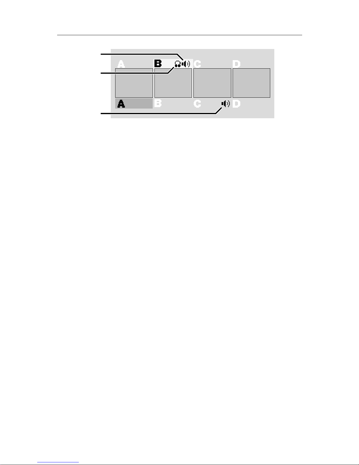
PAGE 38 VIDEONICS DIGITAL VIDEO MIXER
❶
❷
❸
The sound symbol above the preview images (∂ ) shows the CURRENT
sound source (the one that is currently live.) The sound symbol below the
previews (∏) shows the NEXT sound source (where the sound will come
from after the next transition). The headphone symbol (∑) shows which
source can be heard through the HEADPHONE jack.
Sound Strategies
There are several ways to manage audio during a video transition. The
following sections describe various strategies and how to accomplish them.
Audio Follows Video
As you transition from one source to another, you will often want the
“native” sound (the sound that is recorded on the original video tape) to
transition as well. For example, if you dissolve from a shot of a car arriving to
a shot of someone coming into the house, you probably want to hear the car
drive up and you want to hear the door open.
To accomplish this, press the AUDIO/VIDEO button until both the AUDIO and VIDEO lights come on. The sound and video will both transition —
that is, as the effect causes a transition from one source to the next, the sound
will fade. The duration of the fade will match the effect: A slow transition will
cause the sound to fade slowly and a fast fade will cause the sound to fade
quickly. If the transition is a cut (whether performed with the CUT buttons or
the cut effect), the sound will switch at the same instant.
Audio Stays
Sometimes you want the sound to stay with one source as the video
transitions to a new source. For example, as you dissolve from a singer to the
audience’s reaction, you may want the sound of the singer to continue
unchanged as you show the audience.
To do this, press the AUDIO/VIDEO key until only the VIDEO light is on.
The next transition affects only the picture and the sound remains where it
was.
Independent Audio
You may want a totally separate sound track, such as background music,
and not use the native sound at all. This is similar to the “Audio Stays”
Page 44
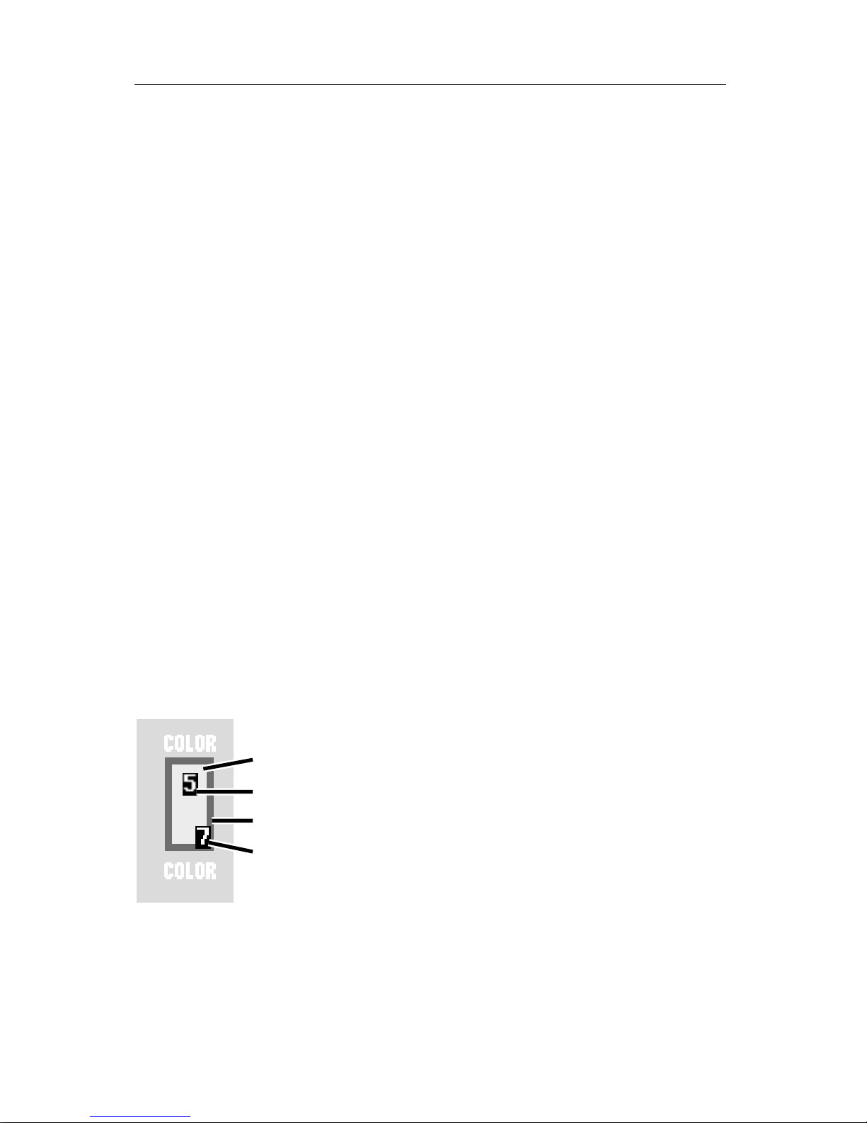
VIDEONICS DIGITAL VIDEO MIXER PAGE 39
strategy except that the sound comes from a source unrelated to the video
sources.
To do this, press the AUDIO/VIDEO button until the AUDIO light is on
and the VIDEO light is off. Transition to the desired sound source. Use the
AUDIO/VIDEO button to turn the AUDIO light off and the VIDEO light on.
Subsequent transitions will affect only the picture. The audio source will
remain unchanged.
Fancy Mixing
You may also want to do something different, such as mixing native sound
with a musical background, having the sound from one scene continue for a
while before fading over to the next scene’s sound, etc. The most flexible
audio arrangement of all is to use an external audio mixer and manually
control all the sound.
You can bypass the MX-1 entirely, connecting the audio mixer’s output
directly to the recorder’s audio input. Or you can connect the mixer’s output
to any of the MX-1’s audio inputs and permanently set that source as your
sound input, as described in the “Independent Audio” section, above. This
allows you to use the mixer when you need flexible control, or use the MX-1’s
audio mix capability when you prefer to have the audio fade automatically,
with video transitions.
Headphones
You can plug a set of headphones into the MX-1. Note that you can use
stereo headphones but the sound delivered to the headphones is mono (the
left and right channels are mixed together).
Usually, the headphones will follow the main sound (you hear the CURRENT sound setting) but sometimes, you may want to monitor the NEXT
source without disturbing whatever is currently routed
to the output. To do this, set the headphone sound to
come from the NEXT source by pressing SHIFT and
DISPLAY at the same time. After the next transition,
the headphones will again monitor the CURRENT
sound source. The headphone symbol (∑, in the diagram presented earlier) shows which source’s sound
can be heard through the HEADPHONE jack.
The Advanced Setup screen (Chapter 5) allows you
to change the headphone volume.
❶
❷
❸
❹
Page 45

PAGE 40 VIDEONICS DIGITAL VIDEO MIXER
Chapter 10 •Chapter 10 •
Borders and Backgrounds
You can define a solid color background to be used behind some
effects and for the COLOR source. You can also add a colored border
that separates the two sources during a transition.
The Solid Color Background
The background color appears in three places:
• In some transition effects, the two sources fill the entire screen. In other
effects, part of the screen is empty during part of the transition. The empty
area is always filled with the background color.
• The background color can also be used as if it were a source, allowing you
to transition to or from a solid color background. CUT→COLOR makes the
background color the CURRENT source. The COLOR source button at the
bottom of the Mixer’s front panel selects the background color as the
NEXT source.
• The solid color is also use in Compose mode (Chapter 16).
Choosing Colors
The border and background colors are shown in the sample color area at
the upper right of the PREVIEW screen. The border and background can be
the same color or they can be different.
The center of the area shows a sample of the background color (∂ ) and the
color’s number (∑). If the border is on, the outer edge shows a sample of the
border color (∏) and its number (π ).
When you first turn the Mixer on, the background color is set to 1 and the
border color is off. Items ∏ and π are missing until you turn the border on.
To set the border color, press BORDER COLOR. To set the background
color, press BACK COLOR. The appropriate color will change each time you
press the button, cycling through the available colors. The color of the sample
and the color number will change to show you the current choice.
Page 46
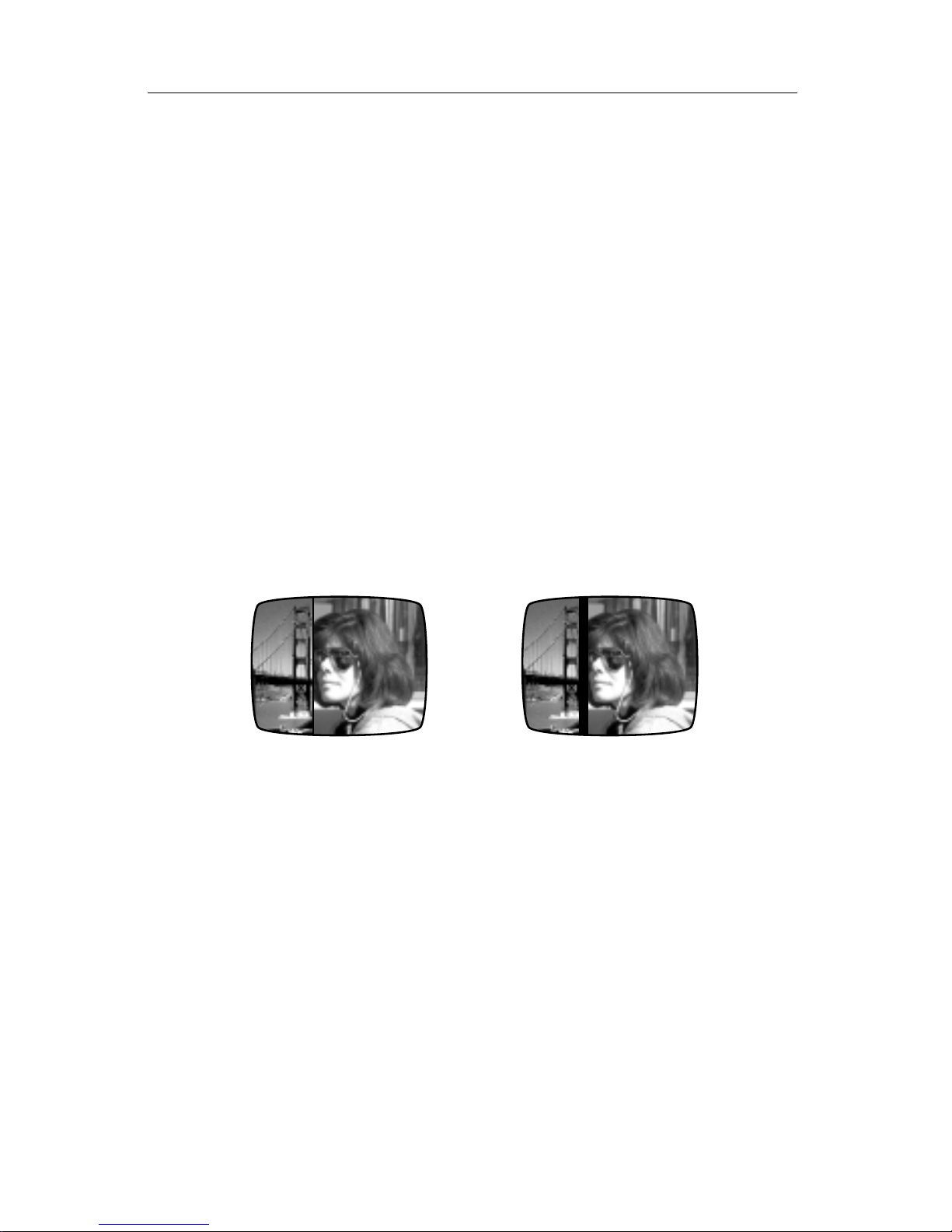
VIDEONICS DIGITAL VIDEO MIXER PAGE 41
Choices 0-8 are pre-defined. Choice 9 is a color you can define, as described in the next section.
0 Black
1 White
2 Gray
3 Red
4 Yellow
5 Green
6 Bright Blue
7 Light Blue
8 Purple
9 User-defined color *
* Color 9 is a medium blue-green until it is redefined. It can be used in
the same manner as any other color.
Hint: You can quickly change to a color by pressing the appropriate color button
and a number key at the same time. For instance, press BACK COLOR and 3 at the
same time to change the background color to red, which is color 3.
Turning the Border On and Off
Here is an example of a wipe with and without a border:
Use the BORDER COLOR button to cycle through the colors. After color 9,
the border will disappear, indicating that the border is off.
Hint: To quickly turn the border off, press SHIFT and BORDER COLOR at the
same time.
Note: The border is automatically turned off when performing a transition
from a source to the solid color background (that is, when A, B, C, or D is
CURRENT and COLOR is NEXT). The border can be used when going from
COLOR to a source.
Defining a Color
Color number 9 can be changed to a color of your choice. The user-defined
color is applied to the background color and the border color. It is also used in
Compose mode (Chapter 16).
Set the BACK COLOR to 9. The sample at the upper right of the PREVIEW
screen will show you the user color as you change it. Press CUT→COLOR to
see the user color fill the output screen.
Page 47
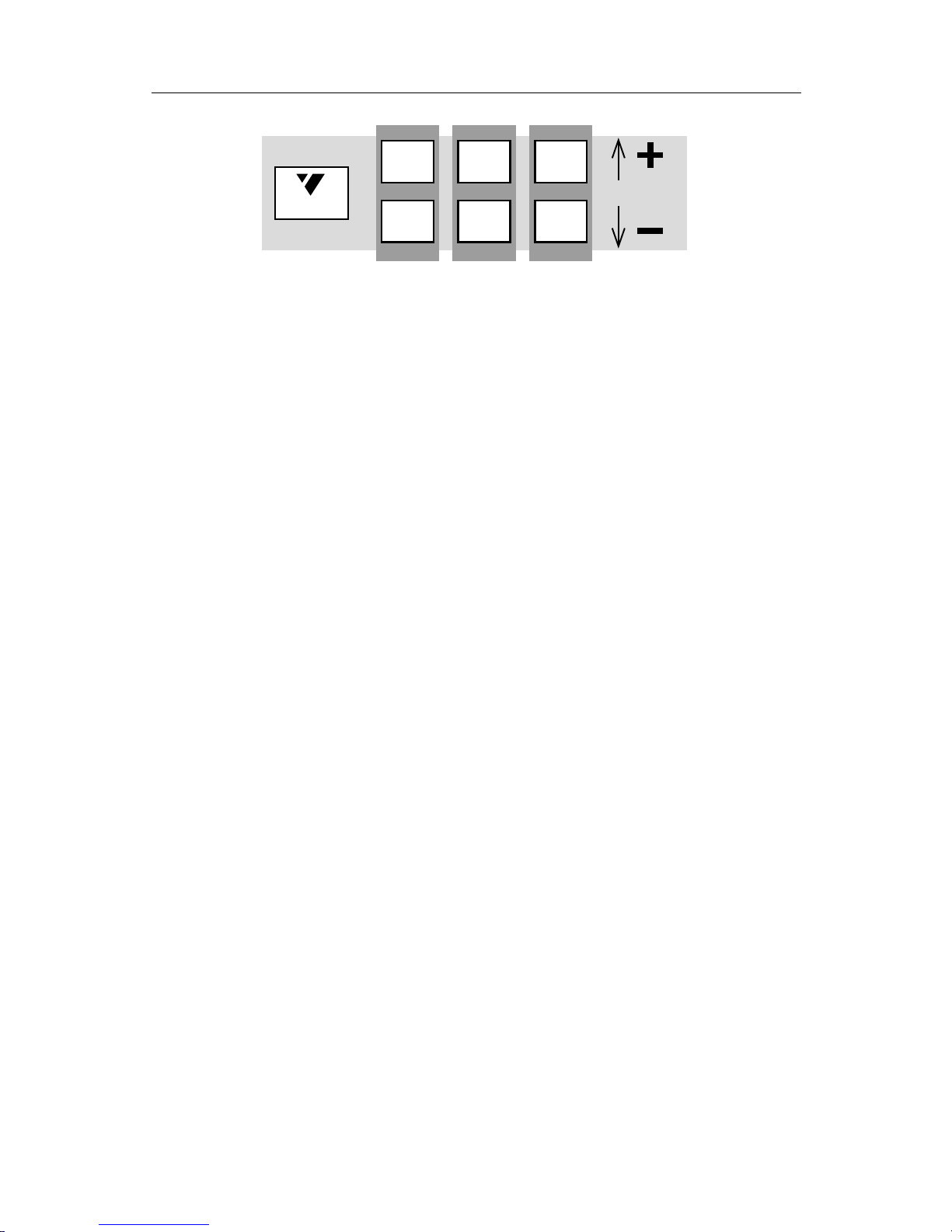
PAGE 42 VIDEONICS DIGITAL VIDEO MIXER
SHIFT
A CB
4
1
5
2
6
3
Once the user-defined color has been selected, the following buttons can
be used to change it.
A Use SHIFT with 1 and 4 to increase and decrease the hue, or color (red,
green, yellow, etc.).
B Use SHIFT with 2 and 5 to increase and decrease the saturation, or degree
of color (dull red vs. bright crimson, for instance). Low saturation gives no
color (black, white, gray) and high values result in strong, vivid color.
C Use SHIFT with 3 and 6 to increase and decrease the lightness of the color,
ranging from dark (low) to light (high).
Hint: Black, white, and gray are achieved by setting saturation to the minimum.
The lightness determines the shade of gray ranging from black (low) to white (high).
The hue is ignored when saturation is all the way down.
User-defined colors are retained until the Mixer is turned off.
Page 48
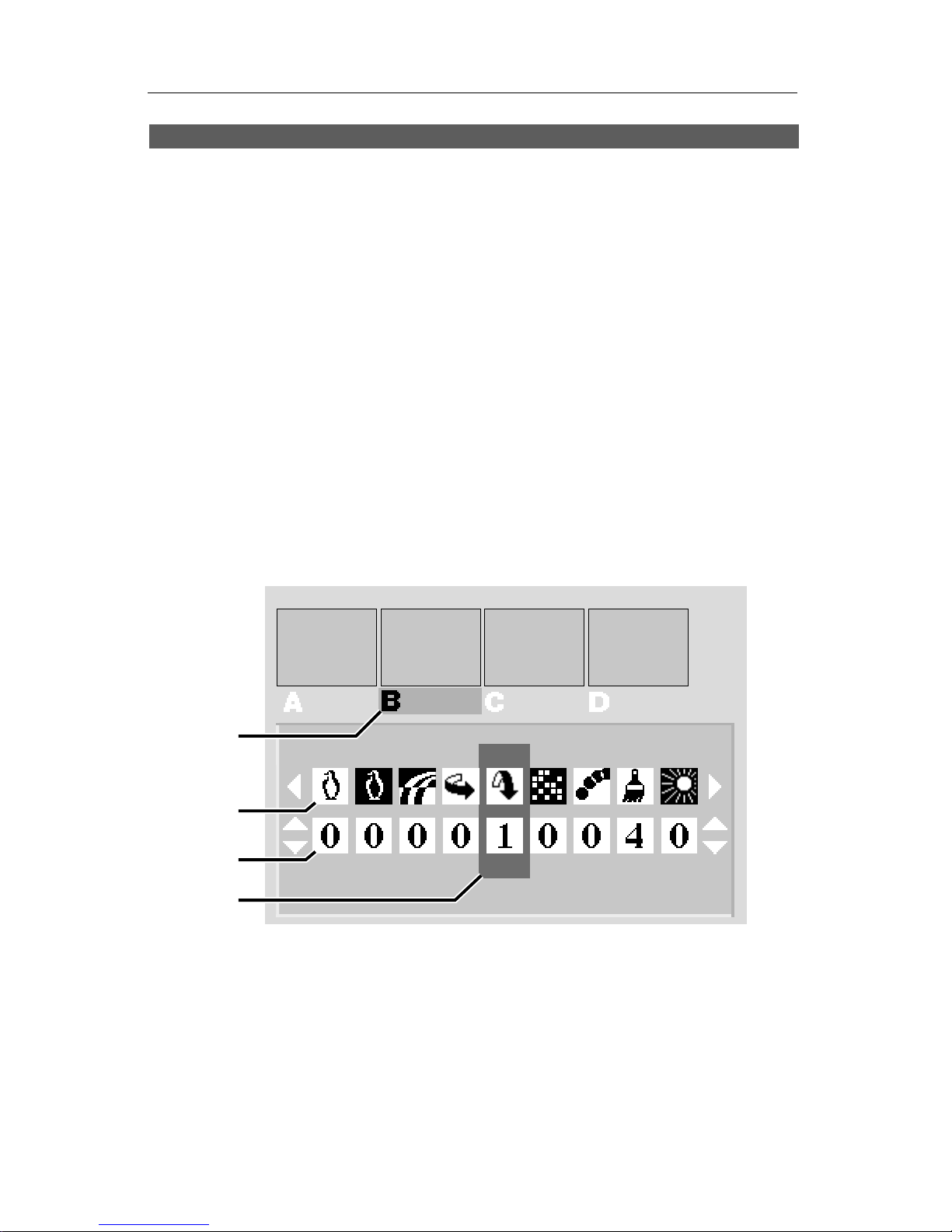
VIDEONICS DIGITAL VIDEO MIXER PAGE 43
Chapter 11 •Chapter 11 • Input Effects
The Mixer offers a wide range of interesting effects that can be
applied to any of the sources.
Any source can be modified easily by applying one or more input effects.
The effect is applied at all times, including during transitions, until you
change it. (Exception: Some input effects are not applied to the foreground
image in PIP, chroma key, and compose. Chapters 13, 15, and 16, provide
details.)
You can combine several effects at once. You can apply any combination of
effects to any source, without restrictions. For example, you can have no
effects on A, change B to black and white, make C a color negative flipped
right-to-left, and use mosaic, strobe, and left-right flip on D.
Defining Input Effects
Press the INPUT F/X button and the PREVIEW screen will show this
display:
❶
❷
❸
❹
The green highlight in the top area (∂ ) determines which source you are
changing. The symbols (∑) show the available effects and the numbers (∏)
are used to turn effects on and off or set their degrees. The blue highlight (π )
tells which effect is being set for the source that is highlighted in green.
• Use the ABCD buttons at the bottom of the MX-1’s front panel to decide
which source is to be modified. The green highlight will change to that
source.
• Use the right and left arrow keys to move the blue highlight and determine
which effect is to be changed.
Page 49

PAGE 44 VIDEONICS DIGITAL VIDEO MIXER
• Use the up and down arrows to change the effect’s value. Some of the
effects are turned on or off: 1 indicates that the effect is on, 0 indicates that
it is off. Others can be set to a numeric value.
• Press OK or PLAY when you’re done.
In the example above, source B has been vertically flipped and a paint
effect with a value of 4 has been applied.
Hint: To quickly turn off all input effects, press SHIFT and OK at the same time
while the input effects screen is displayed, or turn the Mixer off, then on again.
Seeing the Settings
Note that the small previews do not show the results of input effect
settings. There are several ways to see the input effects:
• When you transition to the source, you will see any input effects you have
applied.
• You can also see the results as you make changes. The simplest way is to
set both CURRENT and NEXT to the source you are adjusting before you
display the Input Effects screen. You will see the effect while you make
changes, at full size on the OUTPUT monitor.
• You can see the effects on the PREVIEW monitor instead of on the OUT-
PUT monitor by pressing the DISPLAY button. (DISPLAY alternates the
PREVIEW monitor between the normal PREVIEW screen, NEXT, and
CURRENT.) This is useful when the output is being taped or displayed
live and you want to see the effects without disturbing the output. It’s also
useful when you are working with only one monitor.
For example, consider a nightclub video setting. You are playing a music
video from source A and wish to add a paint effect to the source B, which
is a camera aimed at the dance floor. You want to set up the effect without
affecting the display of the music video (the CURRENT source).
To do this, leave A as CURRENT and set B to NEXT. Press INPUT EF-
FECTS. Use the right and left arrows to highlight the item you plan to
change (the paint effect). Press DISPLAY once to view the NEXT source.
Although you can no longer see the Input Effects screen, you can still alter
its settings using the arrow keys — right and left to change which effect
you are using, up and down to change its settings. You see the changes
immediately but the output is still carrying source A without modifica-
tions.
When you the effect is set up, you can press PLAY to transition to it. Or
you can return to the Input Effects screen by pressing DISPLAY twice
(once to see CURRENT and again to return to the PREVIEW screen).
Page 50
VIDEONICS DIGITAL VIDEO MIXER PAGE 45
List of Input Effects
Here is a description of the effects (from left to right as they
appear on the screen). In all cases, a setting of 0 turns the effect
off.
EFFECT VALUES DESCRIPTION
Black and white 0-1 Changes picture to black and white with all color
removed.
B/W negative 0-1 Lightest values become dark, darkest values
become light but colors are unchanged.
Color negative 0-1 Lightest values become dark, darkest values
become light and colors invert (for example, blue
becomes yellow, red becomes blue-green).
Flip horizontal 0-1 Picture is flipped right-left (as a mirror would).
Flip vertical 0-1 Picture is flipped up-down (upside down). Note that
the video quality of vertically-flipped full-screen
images is reduced slightly.
Mosaic 0-3 Picture is divided up into tiles. Setting 1 divides
picture into many tiny tiles, higher numbered
settings divide into a smaller number of larger tiles.
Thus, high numbers give a more extreme effect.
Strobe 0-7 Picture’s video “frame rate” is slowed. The effect is
that motion is halting, or choppy. Higher numbers
increase the effect. Setting 1 is a fast strobe that
provides a “film look” effect (Chapter 14). Setting 2
makes video look like an old movie. Note that
except for setting 1, the strobe effect is turned off
temporarily while transitions are performed.
Paint (posterization) 0-7 Changes the normally continuous tones of a picture
into a smaller number of levels. Results in a
posterized, or paint, look. Higher numbers provide
an extreme paint effect, lower numbers are more
subtle.
Solarization 0-1 Modeled after a classic photographer’s effect.
Turns the lightest parts of the picture negative
(makes them darker). This only affects pictures
with very bright portions (such as the sky).
FREEZE
Page 51

PAGE 46 VIDEONICS DIGITAL VIDEO MIXER
Chapter 12 •Chapter 12 • Freeze
With the touch of a button, you can freeze a picture on the screen.
Input effects and transitions can also be frozen.
At any time, you can freeze the picture by pressing the FREEZE button.
Whatever is on the output (on the OUTPUT monitor) — whether it’s a single
source, a source with an input effect applied, or two sources in mid-transition
— will be frozen at that instant. You can release the frozen picture by
pressing FREEZE again.
Audio is not affected by FREEZE — it continues normally.
You can freeze the picture in the middle of a transition. The entire transition will freeze, including the video images. When you release the freeze, the
transition will continue. Note: If you freeze a manual transition, use PLAY to
complete the transition — the T-bar will not complete it.
Note the difference between pressing FREEZE and pressing PLAY in midtransition. PLAY halts the transition but the video continues to move. FREEZE
turns the whole picture (sources, transition, and all) into a still image.
You can transition from a frozen image to any source (including the frozen
source). Because holding a frozen picture consumes video memory, some
transition effects behave differently with a frozen picture. Most video scaling,
including compresses and slides, are translated into wipes and other effects
are automatically changed into simpler effects. These effects are indicated by
# in the Effects List at the back of the manual.
Note that some effects, marked by a * in the Effects List, will only operate
in one direction when the CURRENT source is frozen. Reverse has no effect
in these cases.
A technical note: The freeze function captures a field, not a frame. The
frozen field is repeated to form a frozen frame. (See Chapter 20, “Video
Quality.”)
Stop Motion
Normally, the FREEZE button freezes and unfreezes the picture, switching between frozen and moving video. You can perform a “stop motion”
effect instead, in which each press of FREEZE captures a new snapshot of the
video source, replacing the previous image. In this mode, you never see
moving video — each press simply updates the frozen image, like a slide
show of still images.
To use stop motion, press SHIFT and FREEZE at the same time. Now, each
time you press FREEZE, a new still replaces the one on the OUTPUT monitor.
The PREVIEW screen continues to show moving video images so you can
watch for the moments you want. Press PLAY ( or SHIFT and FREEZE again)
to end the stop motion effect.
Page 52

VIDEONICS DIGITAL VIDEO MIXER PAGE 47
Example: Your tape shows two children talking. You press FREEZE at the
appropriate moments, capturing a sequence of glances, gestures, laughs, and
facial expressions.
Page 53

PAGE 48 VIDEONICS DIGITAL VIDEO MIXER
Chapter 13 •Chapter 13 • Chroma Key
“Chroma key” is a sophisticated process, normally found only in
high-end professional equipment, that selectively replaces certain
colors of one picture with a second picture.
What is Chroma Key ?
Chroma key allows you to combine two sources so that a defined range of
colors in one picture is stripped away and replaced with the second picture.
The process of selectively replacing part of a picture in this way is called
keying.
The most common example is the weather forecast. A forecaster appears to
be standing in front of a wall-sized map. The forecaster is actually standing in
front of a blue panel and the map is actually a second video source. A chroma
key device “looks” for that specific shade of blue and replaces it with the map
image. Where the original picture was blue, the map appears; where it was
any other color, the original image (the forecaster) appears.
Advanced Feature
Chroma key is an advanced, professional feature that usually requires
some time and care to set up properly. To achieve a good chroma key, you
should plan on some experimentation. The MX-1 includes several features
that allow you to fine-tune the effect, and it is important that you carefully
follow the steps in this chapter for the best results.
An Example
The following is an example of an effect that could be achieved using
chroma key (this is a simulated black and white version of the on-screen
result):
Page 54
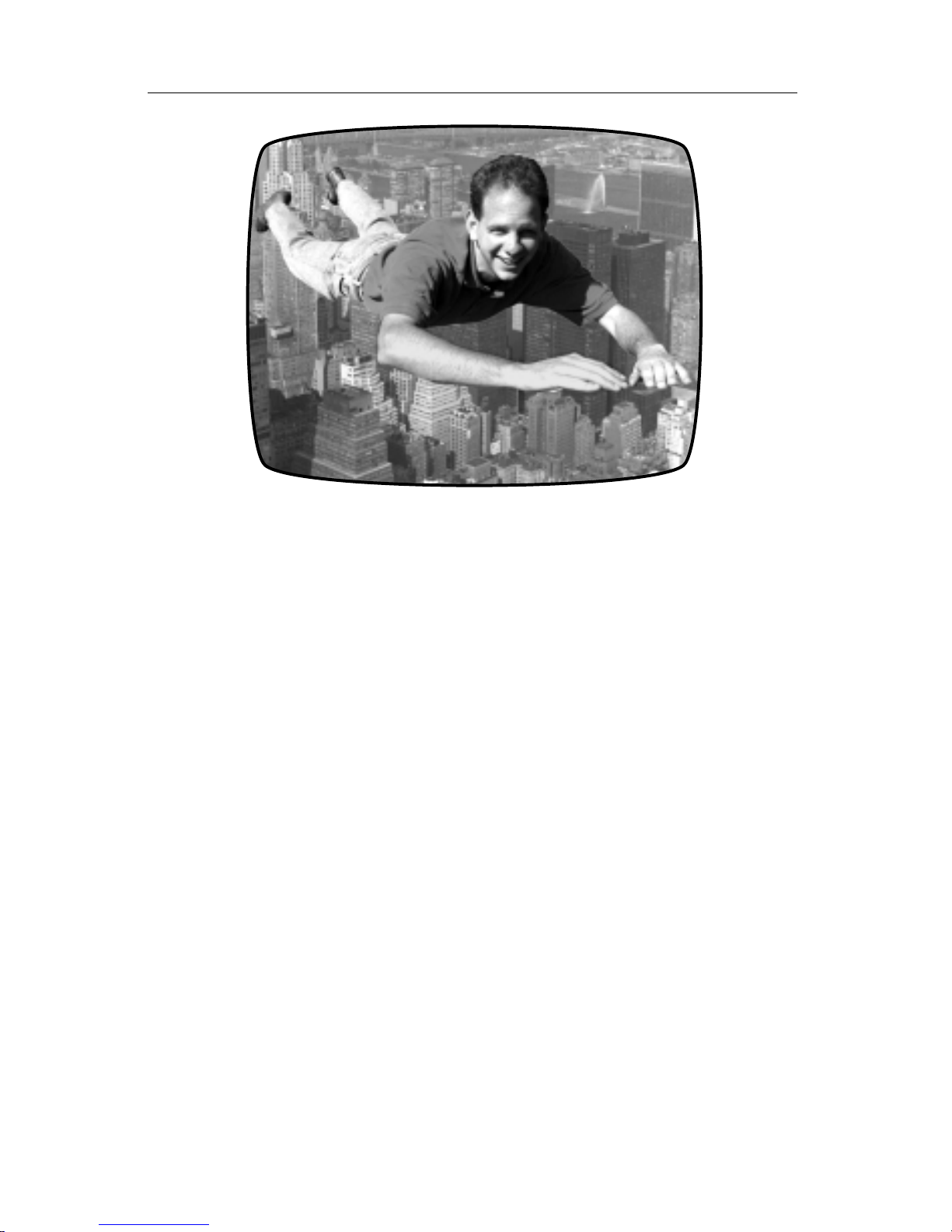
VIDEONICS DIGITAL VIDEO MIXER PAGE 49
Here’s how to perform this kind of superhero feat using the MX-1. Begin
with a large piece of brightly colored cloth tacked to a wall. Drape it over the
ground and over a small platform. The cloth covers the platform, the wall,
and the ground. Have your subject balance on the platform.
Adjust your lighting so the background is evenly lit, so the camera sees
only your superhero and the solid color background. Then use the chroma
key feature of the MX-1 to replace the color of the cloth with some aerial
footage of a city and you have turned a high-flying idea into a dramatic
video!
Setting up the Picture for Chroma Key
The key to a successful chroma key is careful setup of the original picture.
Two guidelines are important:
• You want to be sure that all the areas that should be replaced are the right
color and that the color does not appear anywhere else. For example, if the
superhero’s shirt were close to the color of the chroma key background,
the skyscrapers of the city would appear through portions of the shirt.
• You want to make sure the background is even and does not contain glare
or shadows that will prevent the chroma key circuitry from recognizing it
as background. For instance, if the subject’s shadow darkened the back-
ground enough, the city would not be substituted in the shadows, spoiling
the illusion.
Hints for Chroma Key Setup
• Flying a man over a city is an ambitious chroma key project and it would
be a good idea to start with something simpler. Tabletop miniatures are
Page 55

PAGE 50 VIDEONICS DIGITAL VIDEO MIXER
particularly good for chroma key experimentation because lighting is
simpler to control.
• Be sure no other portion of the image shares the key color (the color of
background that will be keyed out). The MX-1 can chroma key on any
color, so you can select a background color based on your subject. Bright
blue or green are the colors most commonly used in professional chroma
key studios.
• Use even lighting on the background, to eliminate hot-spots and shadows.
Lights coming from the camera’s direction tend to reflect off the back-
ground, creating glare. Multiple lights coming from several directions are
particularly good as they tend to fill in the shadows.
• Allow enough room between the subject and the chroma key backdrop to
allow you to light the subject without casting shadows or excess light on
the backdrop.
• Use non-reflective background material.
• Reflectors are an inexpensive and flexible way to bring in light from other
directions, especially in outdoor lighting.
Performing a Chroma Key
In the following steps, assume that source A is the foreground source —
the picture with the solid color backdrop that will be replaced. In the previous example, that would be our superhero. Source B is the background
picture — the city, in the example.
Select Sources
The first step is to determine which sources to use for the chroma key:
• Use the appropriate CUT button to choose the background image. In this
example, you would press the CUT→B button to choose the footage of the
city. This source will appear on the OUTPUT monitor.
• Use the ABCD buttons to set the NEXT source to be the foreground source.
In this case, you would press A to choose the image of the superhero on
the chroma key backdrop.
Identify Key-Colors
The next step is to identify the range of colors that will be replaced. You
can chroma key on any color in the foreground scene.
• Press the CHROMA KEY button. The normal PREVIEW screen will be
replaced by a full-screen image of source A (the superhero). A small,
flashing cross (called a “cursor”) will appear on the image.
• Use the arrow keys to position the cursor over an area that contains the
chroma key color (the color of the chroma key background).
Page 56

VIDEONICS DIGITAL VIDEO MIXER PAGE 51
• Press OK. All areas of the picture that match the color under the cursor
will be replaced by the background source (B).
• You can increase the range of colors that will be keyed by identifying
additional key-colors. To do this, use the arrow keys to position the cursor
over a portion of the image that has not been keyed away and press the OK
button again. Keep doing this until you have captured the entire background. Each time you press OK, the Mixer widens the range of colors it
keys to include the color under the cursor at that moment. You can pick as
many points as you wish. (You can also adjust the keyed-color range, as
explained in the next section.)
• If you accidentally overdo it and pick a point that keys out part of the
subject, you can reverse the choice by pressing SHIFT and OK simultaneously. This removes the effect of the last point you picked. It also
removes all fine-tuning (as explained in the next section).
Fine-tuning the Key-Colors
You can fine-tune the chroma key effect so that more or less of the foreground video will be keyed. You can separately adjust the range of colors that
will be keyed, or the range of video brightness that will be keyed:
• To adjust the brightness range, hold SHIFT and press the up and down
arrows. SHIFT+UP increases the range of brightness values that will be
keyed, so more of the foreground picture will be replaced with background image. SHIFT+DOWN decreases the brightness range, reducing
the portion of the picture that will be keyed.
• To adjust the color range, hold SHIFT as you press the right and left arrows.
SHIFT+RIGHT increases the range of colors that will be keyed, so more of
the foreground picture will be replaced with background image.
SHIFT+LEFT decreases the range of key-colors, reducing the portion of
the picture that will be keyed.
Adjusting the Scene
If part of the subject is too similar to the color of the background, you may
be unable to capture the entire background without also capturing some of
the subject. You will need to adjust the lighting or use a background with a
different color.
Cancelling the Settings
You can cancel all the chroma key settings by pressing the SHIFT and
CHROMA KEY buttons at the same time. This removes all the key-color
points you have selected (as if you had never used the OK button) and it
removes all fine-tuning (as if you had never used SHIFT with
the arrow keys).
You can eliminate the effect of the last key-color point (in
effect, removing the last OK press) by pressing SHIFT and OK
at the same time. This also removes all fine-tuning.
Page 57
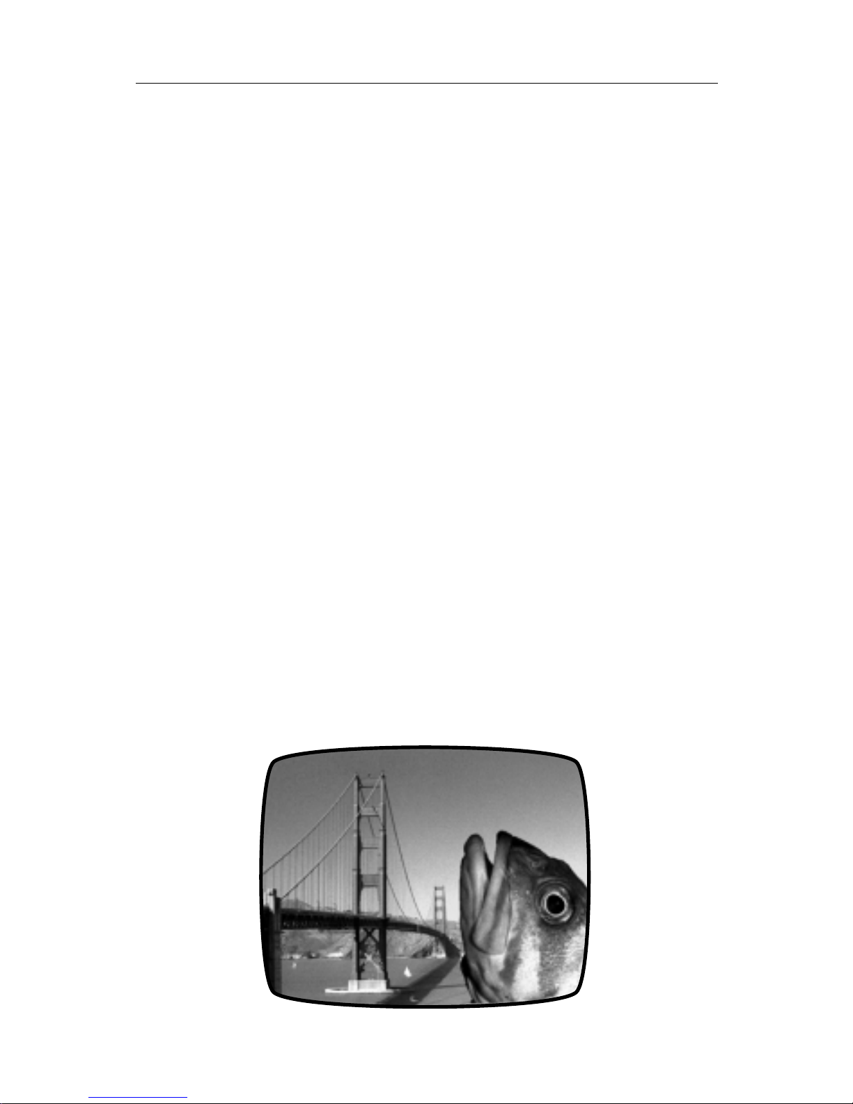
PAGE 52 VIDEONICS DIGITAL VIDEO MIXER
Performing the Chroma Key
When the PREVIEW screen shows the desired result, press PLAY. The
picture on the OUTPUT monitor will be replaced by the chroma keyed image.
In our example, we would see a transition from the city footage to the same
footage with the superhero added. Press PLAY again to cut back to the
background source.
You can also dissolve between the background source and the chroma
keyed image by using the manual Take-Bar rather than pressing PLAY.
Transitions To and From Chroma Key
You can cut or dissolve directly between the chroma keyed image and the
background source (as described in “Performing the Chroma Key,” above).
You can transition to other sources indirectly: First transition to the background source, then transition to the final source.
Freeze and Input Effects
You can apply input effects and freeze to the background image but not
the foreground.
• To use input effects, apply them to the CURRENT source before you press
CHROMA KEY.
• To FREEZE the background, press FREEZE either before or after you
press CHROMA KEY.
• Any effects applied to the NEXT source will be ignored during chroma
key.
Ending Chroma Key
When you are finished using chroma key, press DISPLAY or CHROMA
KEY.
Page 58

VIDEONICS DIGITAL VIDEO MIXER PAGE 53
Chapter 14 •Chapter 14 • More Effects
Some of the Mixer’s transitions also act as effects. When set part
way, they alter the picture in useful ways. You can also create color
or black references.
Tint Effect
You can use the background color capability to tint a picture. To do this,
set up a dissolve (effect 1) from the desired source to COLOR. Define the
background color to be the desired tint. Use the Take Bar to manually
perform the transition.
The dissolve will begin with normal, untinted video. As you move the
Take Bar, the coloration will increase. At the end of the effect, the screen will
be pure color with no video at all. Adjust the bar for the desired amount of
color tint and record the result.
The “Thin Man” Effect
You can make a video image thinner or wider than normal. When applied
slightly, this effect can make everyone in the picture look a bit thinner (or
heavier, if you want to make enemies) than they do in real life.
To accomplish this, set the background color to black and choose COLOR
as the CURRENT source. Choose effect 41 (Horizontal Curtain Expand) and
use the Take Bar. The video will start very thin and expand to a normal fullscreen image at the end. Adjust the bar for the desired amount of “video
weight loss.”
To make the video wider, use the same technique with effect 81.
Luminance Key
Luminance key is similar to chroma key in that certain parts of the picture
are replaced by a second picture. But in luminance key, the replacement is
gradual and is based on the lightness of the original picture, rather than its
color. Example: You could make a video ghost story in which luminance key
is used to make the ghost transparent.
Let’s call the original picture A and the second picture B. In luminance
key, the lightest portions of A are replaced by B. The darkest portions of A are
unchanged. Portions between black and white are a mix, with more of the
original A in the darker areas, more B in the lighter areas.
Performing a Luminance Key
Effects number 237 and 238 are luminance keys. Effect 28 (one of the “Top
30 effects”) is the same as effect 237.
Page 59
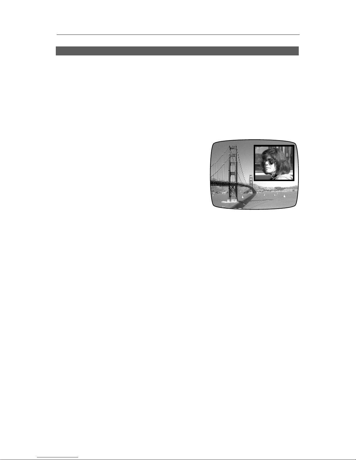
PAGE 54 VIDEONICS DIGITAL VIDEO MIXER
Chapter 15 •Chapter 15 •
Picture-In-Picture (PIP)
When one picture can’t quite tell the story alone, “picture-inpicture” allows you to combine two images on one screen, placing
one in a small rectangle. The inset picture can be scaled to any size
and moved to any location on the screen.
Definitions
Picture-In-Picture (PIP) places one moving
video picture (the foreground video) in a small
rectangle (called a window) on top of another
video image, (the background video).
Applications
With PIP you can show two events at once or give the viewer two points of
view. For instance, you can show an instructor explaining how to assemble a
machine and in a small window in the corner, show a close-up of the procedure that is being described. In a video of a sporting event, you can show the
scoreboard in a small window while the action fills the rest of the screen. Or
you could watch two games at once!
Any two sources can be used for the foreground and background videos.
You can move the window to any place on the screen, set it to any size, stretch
it horizontally or vertically, and add a colored border. You can freeze the
background video. You can move the superimposed window while the resulting PIP image is recorded.
Creating a PIP Image
Choose the Background and Foreground Sources
Begin by setting the CURRENT and NEXT sources: The CURRENT source
will become the background image and the NEXT source will become the
foreground.
Example: To make a PIP that looks like the above illustration, if the bridge
is on source A and the woman is on source C, press CUT→A to make the
bridge the CURRENT source and press the C button to make the woman the
NEXT source.
You can choose COLOR as the background image, to place a moving
picture on a solid color. You cannot use COLOR as the PIP image — to do
that, use Compose (Chapter 16).
Page 60
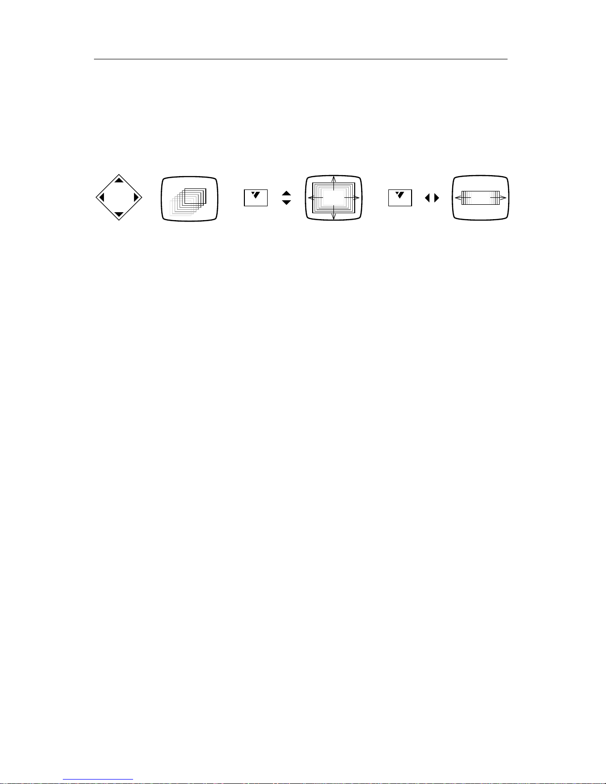
VIDEONICS DIGITAL VIDEO MIXER PAGE 55
Enter PIP Mode
Hold SHIFT as you press ZOOM/P-IN-P. The PREVIEW screen changes
to show the background video with the foreground video inset in a small
window.
Move and Size the Window
=
SHIFT
=+
SHIFT
=+
• Use the arrow keys to move the rectangle.
• To make the rectangle larger or smaller, hold SHIFT and use the up and
down arrows. This changes the height and width of the rectangle together. In other words, SHIFT+UP and SHIFT+DOWN changes the
rectangle’s size but does not change its proportions (that is, the shape, or
“aspect ratio,” remains the same).
• To change the shape of the rectangle, use SHIFT with the right and left
arrows. SHIFT+RIGHT makes the rectangle wider and SHIFT+LEFT makes
it narrower. The height remains the same.
You can go back and forth, readjusting the size and shape as needed.
Anytime you use SHIFT with the up and down arrows to adjust the size,
the rectangle automatically snaps back to the normal proportions so the
video is not stretched out of shape.
Freezing and Input Effects
You can freeze the background image by pressing FREEZE. You can use
FREEZE to freeze and unfreeze the image anytime — before you enter PIP
mode, while you are positioning the PIP image, or after the image has been
displayed on the OUTPUT monitor.
Any input effects applied to the foreground source are ignored.
You cannot freeze the foreground image (NEXT source). Use the Compose
feature (Chapter 16) if you want a picture made up of still images.
Add Borders
You can add colored borders to frame the PIP window. Press BORDER
COLOR repeatedly to cycle through the available colors and border-off. You
can also use the advanced color features described in Chapter 10, “Borders
and Backgrounds” to quickly change the color or to define your own color.
Display the Results
When you are happy with the PIP image on the PREVIEW screen, you can
cut or dissolve the output image from the CURRENT source to the PIP image.
Press PLAY to perform a cut; use the Take Bar to perform a dissolve.
Page 61

PAGE 56 VIDEONICS DIGITAL VIDEO MIXER
You can cut or dissolve from the PIP image back to the CURRENT source
by using the PLAY button or Take Bar.
More Changes
You can continue to modify the PIP image even after it is displayed on the
output, using any of the PIP features described above: You can move or resize
the window, freeze the background image, turn the border on and off and
change its color.
Since all movement occurs in steps, moving the window as it is recorded
will result in jumpy motion — it’s better to position and size the window,
then record. Smooth motion of the PIP window is not possible.
Ending PIP Mode
When you are finished using PIP, press SHIFT+PIP again or press DISPLAY until you see the PREVIEW screen.
Page 62
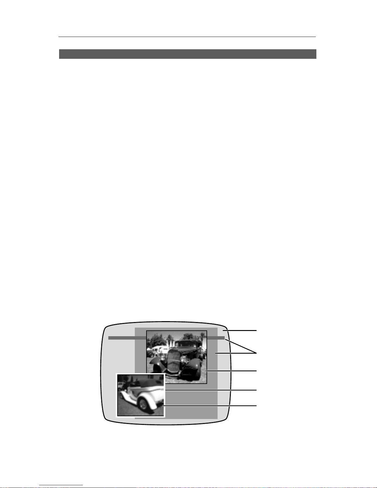
VIDEONICS DIGITAL VIDEO MIXER PAGE 57
Chapter 16 •Chapter 16 • Compose
The MX-1 Mixer will allow you to create an elaborate composite
screen made up of picture elements, solid colors, lines, and rectangles. You can perform limited transitions from the composed
image to a source.
What is Compose?
Compose allows you to design your own image. It can range from a simple
still picture with a border added, to a complex assemblage of pictures, lines,
and rectangles.
Composed screens begin with a background (a solid color or a still or
moving video image). The following elements can be added:
• Lines and rectangles: You can incorporate a rectangle or line of any color
and any size, with or without a border.
• Still pictures: Frozen frames of a moving picture can be placed anywhere
in the composition. They can be scaled to any size and a border can be
placed around them. You can have an unlimited number of stills in a
composition.
Note: Compose allows you to place still video images only. Only the
background video can be moving. To place a moving video image in a
window, see Chapter 15, “Picture-In-Picture.”
• Color bars: You can use color bars as your background.
• Holes: You can cut a “hole” in the composed image, removing other
elements and leaving the original background video.
❶
❷
❸
❹
❺
• Combined elements: Elements can be overlapped to create borders and
other effects. In this example, we started with a solid color screen (∂ ) and
placed a rectangle and a line (∑), followed by a still picture (∏). A white
Page 63

PAGE 58 VIDEONICS DIGITAL VIDEO MIXER
rectangle was added (π ) and a second still (∫ ) was centered on the white
rectangle.
Rules for Compositions
The first step is to plan your composition. You can create almost anything
with the available elements, but there are a few rules to keep in mind.
• Each element you draw erases anything it overlaps. For instance, if you
draw a rectangle that overlaps part of a picture, the overlapped portions of
the underlying picture are gone forever. If you decide you want the erased
portions back, you will have to redraw them.
• Reducing a still or moving video image can introduce minor pixel arti-
facts, as described in Chapter 20, “Video Quality.”
• A composition cannot be saved except by videotaping it.
Choosing the Background
Before you enter Compose mode, choose the source for the background.
The CURRENT source at the time you enter compose mode becomes the
background upon which you will build your composition. So the first step is
to set the CURRENT source to be the desired image:
• If you would like a solid color background, choose the color using the
BACK COLOR settings (Chapter 10, “Borders and Backgrounds”). Make
COLOR the CURRENT source, using the CUT buttons or a transition.
• If you want moving video as the background, use the CUT buttons or a
transition to make the CURRENT source the one you want in the back-
ground.
• If you want a video still, make the desired source the CURRENT source
and use FREEZE to freeze the picture.
• You can apply input effects to the background image before you enter
Compose mode. Use of some input effects will disable the FREEZE func-
tion.
• You can also use color bars (a set of bars in standard colors) as your
background by pressing SHIFT and COLOR at the same time after you
enter Compose mode.
Positioning and Sizing an Element
Once the background has been selected, press the COMPOSE button. The
normal PREVIEW screen will replaced by a full screen image of the CURRENT source (the one on the OUTPUT monitor), with a flashing rectangle
superimposed. The flashing rectangle is used to position the elements you
will be adding to the image. Use the arrow keys to move and size the
rectangle:
Page 64

VIDEONICS DIGITAL VIDEO MIXER PAGE 59
=
SHIFT
=+
SHIFT
=+
• To make the rectangle larger or smaller, hold SHIFT and use the up and
down arrows. This changes the height and width of the rectangle together.
In other words, SHIFT+UP and SHIFT+DOWN changes the rectangle’s
size but not its proportions (that is, the shape, or “aspect ratio,” remains the
same).
• To change the shape of the rectangle, use SHIFT with the right and left
arrows. SHIFT+RIGHT makes the rectangle wider and SHIFT+LEFT makes
it narrower. The height remains the same.
You can go back and forth, readjusting the size and shape as needed.
Anytime you adjust the size, the rectangle automatically snaps back to the
normal proportions so the video is not stretched out of shape.
Placing the Element
Once the flashing rectangle has been positioned, you are ready to determine what fills it.
Solid Color Rectangle
To fill the rectangle with a solid color, press the COLOR key at the bottom
of the Mixer’s front panel. The flashing rectangle will be filled with the
current choice of background color. You can change the color using the
BACK COLOR button (or the COLOR button again) to cycle through the
predefined colors. You can also define your own color as described in Chapter 10, “Borders and Backgrounds.”
Placing a Line
Since a line is simply a narrow rectangle, the method for drawing a line is
the same as that for drawing a rectangle. Use SHIFT with the up and down
arrow keys to determine the line’s height. Then use the right and left arrow
keys to stretch the rectangle to make the line. You can make vertical or
horizontal lines but not diagonals.
Placing Still Video
After you have positioned the rectangle, choose the video you wish to
place using the ABCD buttons at the bottom of the front panel (the way you
normally choose the NEXT source). The source you selected will fill the
rectangle. If the rectangle was stretched out of its normal proportions, then
the picture will be stretched accordingly.
You can watch the moving image and freeze it any point by pressing
FREEZE. If you miss the precise instant you wanted, press FREEZE again to
unfreeze the image and try again. (If you do not freeze the image manually, it
Page 65

PAGE 60 VIDEONICS DIGITAL VIDEO MIXER
will automatically freeze when you use the arrow keys to place a new
element.)
Input effects are not applied to videos that are placed in the composed
screen, except for the background video.
Note: While the video in the rectangle is still moving, occasionally lines
may appear alongside the rectangle. This is especially likely if the rectangle
contains video that is non-standard, as when a VCR cues or reviews (searches).
If this occurs, position the rectangle over the extraneous lines and use
SHIFT+OK to redraw the background image, then redo any elements that
have been disturbed.
Borders
To add a border, place a rectangle or video picture, as described previously, and press BORDER COLOR. You can change the color by pressing
BORDER COLOR again and again until you see the desired color and you can
define your own color. Once painted, a border cannot be removed except by
using SHIFT+OK (see “Holes” section, below.)
Hint: You can also make a border of any width. To do this, place a solid color
rectangle as described previously. Use SHIFT+DOWN to reduce the rectangle
slightly, then place a still video image. This is a handy way to neatly center a picture
inside a colored rectangle, creating a border of any size. You can also make multiple
borders by repeating this step.
Holes (Erase)
If you press SHIFT and OK at the same time, everything under the flashing
rectangle will be removed, leaving the original background video. You can
use this feature to erase elements or to make a “hole” through which the
background video shows.
Adding More
After you have placed an element in the composition, use the arrow keys
to move or resize the rectangle and add more elements.
Making Changes
To change any of the elements on the composed screen, simply draw a
new element over the one you wish to change. To “erase” an element,
position the flashing rectangle over the element and press SHIFT and OK to
replace it with the background video.
Recording the Result
Press PLAY to display the resulting Compose screen on the output. The
result will be a cut from the CURRENT source to the composed screen.
You can also dissolve from the CURRENT source to the composed screen
by using the Take Bar rather than pressing PLAY.
Page 66

VIDEONICS DIGITAL VIDEO MIXER PAGE 61
You can cut and dissolve back and forth between CURRENT and compose
using PLAY or the Take Bar but note that if you transition to any other source,
the composed screen is erased.
While the composition is being displayed, you can freeze and unfreeze the
background image by pressing FREEZE. You can also add new elements.
Ending Compose Mode
Press COMPOSE or DISPLAY to leave the Compose screen. The Compose
screen will be erased when you leave Compose mode.
Page 67

PAGE 62 VIDEONICS DIGITAL VIDEO MIXER
Chapter 17 •Chapter 17 •
Sequences (LEARN mode)
Do you find yourself doing the same steps over and over? Would
you like to set up some transitions ahead of time and perform each
one at the press of a button? Let the MX-1 perform for you! The
“learn” function can record your actions and play them back.
What is LEARN Mode?
The Learn function watches and remembers as you perform transitions,
then allows you to play them back.
Each transition consists of a transition setup (choice of audio and video
sources, input effects, transition effect number, background and border,
transition speed, etc.) followed by PLAY. The CUT buttons also perform a
transition.
The MX-1 will store one learned sequence containing up to 25 transitions
(see “Number of Steps” later in this chapter).
Notes
• You can do the following in a learned sequence: Perform transitions,
including use of reverse and speed settings; choose CURRENT and NEXT
sources; use freeze; define border and background colors; define input
effects; and transition audio, video, or both.
• You cannot do the following as part of a sequence: Create or transition to
COMPOSE screens; use chroma key; use the demo; use PIP.
• A manual transition (using the Take Bar) is memorized as an automatic
transition at the currently set speed. In other words, it is remembered as if
you had used the PLAY button rather than the Take Bar.
• The learned sequence is erased when you turn the MX-1 off or it loses
power, or when you learn a new sequence.
Learning a Sequence
To learn a sequence of transitions:
• Be sure the PREVIEW screen is displayed on the PREVIEW monitor. If it is
not, press DISPLAY until it is.
• Press LEARN. The POWER light will blink while you are in Learn mode.
Page 68

VIDEONICS DIGITAL VIDEO MIXER PAGE 63
• Perform a series of transitions. Each transition will be performed as usual
and will be simultaneously memorized. You can use any normal method
for performing these (such as use of numbers, arrow keys, or large effect
buttons) but using the number keys is best since it uses fewer learn steps.
If you press COMPOSE, CHROMA KEY, SHIFT+PIP, DEMO, or
SHIFT+DEMO, LEARN mode ends because these actions cannot be stored
in a sequence. The steps entered before these keys were pressed remain in
the sequence.
• When you have completed your transitions, press LEARN again. The
POWER light will stop blinking.
If you record the maximum allowable number of transitions, filling memory,
LEARN mode will end automatically.
Playing the Sequence
To play the sequence, be sure the PREVIEW screen is displayed, then press
SHIFT and PLAY at the same time. The PREVIEW screen will go blank for a
moment and the POWER light will flash rapidly. From then on, each time
you press PLAY, the next transition in the sequence will be performed. After
the last step has been played, the sequence will start over again.
If you use the Take Bar instead of PLAY to play a learned sequence, it will
override the SPEED setting and play the next transition in the sequence
manually.
A GPI trigger input (described in the “GPI Trigger” section of Chapter 19,
“Editing and Other Applications”) can also be used to play the steps in a
sequence. In other words, a GPI pulse acts exactly the same as pressing
PLAY.
Ending Sequence Playback
Press SHIFT and PLAY again to stop playing the sequence. You can also
stop playing a sequence by simply starting a new transition (in other words,
by using any control other than PLAY or the Take Bar).
The POWER light will stop flashing and the PLAY button and Take Bar
will act normally, playing the effect indicated on the screen rather than the
learned sequence. The sequence will remain in memory while you perform
other effects.
Changing the Sequence
A learned sequence can be replaced by simply learning a new sequence.
When you press LEARN and start a new sequence, the old sequence is
immediately erased. You can also erase a sequence by turning the Mixer off
and then on again. You cannot append additional steps to a sequence.
Page 69

PAGE 64 VIDEONICS DIGITAL VIDEO MIXER
Number of Steps
The learned sequence can contain up to 50 “steps.” Each transition effect
number counts as one step and each press of the PLAY button counts as one
more. If your learn sequence consists entirely of effect numbers followed by
PLAY, then 25 transitions can be stored.
Other buttons count as one more step including, SPEED, FREEZE, SETUP,
INPUT F/X, arrow keys, CURRENT and NEXT source buttons, etc. For
instance, if you set B as the NEXT source, press SPEED three times, enter 5 as
your effect, and press PLAY, you will use 6 steps.
Selecting an effect using the number keys takes just one step, no matter
how many number buttons are used (for instance, 125 takes three buttons but
occupies only one step). Selecting an effect using the arrow keys will consume one step for each arrow pressed. If you are trying to fit as many
transitions as possible into the sequence, use the number keys to choose the
effect.
Each complete transition occupies a minimum of two steps — one for the
effect number and one for PLAY. If you press PLAY without entering a new
transition effect number (to repeat the last transition), two steps are still used.
A CUT also occupies two steps.
Page 70

VIDEONICS DIGITAL VIDEO MIXER PAGE 65
Chapter 18 •Chapter 18 • TBC
The MX-1 includes a time base corrector for top quality results.
This section describes some details of TBC operation.
Skip This Chapter?
Note that because the TBC operates automatically, most users can skip the
rest of this chapter, which contains technical details of TBC operation.
What is a TBC?
A time base corrector modifies a video signal so that all the elements that
make up the picture — the lines, fields, frames, and individual dots (pixels)
— appear on the OUTPUT screen exactly where they should. It compensates
for the shifting and wavering that are inherent in most VCRs, camcorders,
and other video devices. See the Digital Video Primer pamphlet for more
information.
Using the TBC
The MX-1’s built-in TBC is always active — it cannot be disconnected or
disabled and no user action is required to turn it on.
Dual TBC Mode
It is possible to use the MX-1 as a dedicated two-channel TBC which
performs time base correction on two separate channels. Here’s how:
• Set up one source as the CURRENT source and a second one as the NEXT
source.
• Press the DISPLAY button once. This makes the PREVIEW OUT carry the
NEXT source, instead of showing the PREVIEW screen.
• The OUT jack carries the CURRENT source as usual.
The result is that the two sources will each appear on its own output and
both will have the benefit of time base correction.
While acting as a dual TBC, the Mixer can still perform cuts, as usual. Use
the CUT buttons to change the CURRENT source (the one that appears on the
OUT jack). Use the ABCD buttons to choose the NEXT source (which appears
on the PREVIEW jack).
Page 71

PAGE 66 VIDEONICS DIGITAL VIDEO MIXER
Frame Rate Lock Setting
There is one option you can set that affects the operation of the MX-1’s
TBC. The option, frame rate lock disable, reduces or eliminates the need for
dropped or duplicated video fields, a common consequence of TBC use. The
option is normally set to 0 to enable locking and you will not need to change
it unless you are using equipment that demands an unusually accurate time
base. The following section describes it in detail.
What is Frame Rate Locking?
A TBC forces the video output to an exact rate, independent of the frame
rate of the input signals. If the input video is coming at a slightly slower rate,
there will come an instant when the output gets ahead of the input and a
video field will have to be repeated. Conversely, if the input is running
slightly faster than the output, eventually a field has to be dropped. The
visible result is a small hesitation or gap in the action and a vertical jump in
the picture, at rare intervals. This is an inherent, unavoidable artifact of TBC
operation. In most cases, the rates are very close and frame drops and
duplication are very rare (hours apart) and unobtrusive.
The MX-1’s automatically compensates for this. It adjusts the frame rate of
the output by very small amounts at the end of each video field, to reduce
differences between the input and output rates. This reduces or eliminates
the need to drop or duplicate fields. However, it does mean that deviations in
input frame rates will cause the output frame rate to be very slightly offstandard.
This slight change in frame rate is of no consequence in most setups and
we recommend you leave the setting off (0, its normal setting). If you are
connected to equipment that requires very exact frame rates, you can change
the setting to 1 and the timing of the output will be more exact and fields will
be dropped or duplicated as required.
Note that in real life situations, neither setting will result in serious picture
problems unless the timing of the input video is beyond accepted standards.
How to Turn Frame Rate Locking On and Off
To change the Frame Lock Disable Setting, press SHIFT and SETUP at the
same time to enter Advanced Setup mode (Chapter 5, “Setup Screen”) and
change the setting. “1” disables locking and “0” turns locking back on.
Vertical Interval Data
Time code, closed captioning, and other data in the vertical interval should
be added after mixing (downstream from the MX-1) since dissolves and other
transitions would mix the data signals, making them unreadable. Depending
on how data has been added and the accuracy of a source’s time base, vertical
interval data in the sources may be removed by the TBC.
Page 72

VIDEONICS DIGITAL VIDEO MIXER PAGE 67
Answers About the MX-1’s TBC
Here are answers to some commonly asked technical questions. (Some of
this is highly technical but don’t be concerned — you don’t need to understand any of it to have full use of the Mixer and its TBC.)
• There are no TBC control options other than the frame rate lock described
previously. The entire signal is always corrected, including the horizontal
and vertical intervals.
• The TBC is a dual-field TBC. It corrects two sources at once. Since all
transitions and effects use only two of the four sources at any time, the
dual field TBC can correct the time base of the entire output signal,
transitions and all.
• The Mixer’s TBC is an infinite-window TBC.
• The output sync of the TBC is independent of all inputs. There is no way to
synchronize it with an external sync or with any of the inputs.
Page 73

PAGE 68 VIDEONICS DIGITAL VIDEO MIXER
Chapter 19 •Chapter 19 •
Editing and Other Applications
With its four inputs, frame synchronizer, time base corrector, and
audio capabilities, the MX-1 Digital Video Mixer is adept at mixing
multiple video sources in a wide variety of applications, including
both single- and dual-source editing.
The Video Mixer can mix video sources but it does not control them. This
chapter describes how to control your video sources so the correct material is
playing at the correct times. It starts with the simplest cases and progresses to
complex video editing setups that require the synchronization of as many as
four videotape players.
Chapter 4, “Connecting Editing Equipment,” explains how to connect
editing equipment such as titlers and video processors.The Digital Video
Primer contains additional information on editing.
Live Mixing
A simple application that does not depend on controlling sources at all is
live mixing, in which several cameras, or other sources, are fed through the
Mixer and displayed live or recorded as the event happens. The Mixer’s four
inputs make live productions particularly easy, as cameras and running
sources can be switched and transitioned at will.
Editing with Untimed Sources
Another application that does not require tight control of VCRs is the
combination of footage that is not time dependent or is only loosely timed.
For instance, you might wish to mix totally unrelated background footage,
such as computer-generated graphics or scenery footage from a laser disc.
Another example: You might be taping a performance or speech and
dissolve over to some audience footage from time to time. It wouldn’t matter
whether the audience shots were precisely synchronized with the performance.
You might have untimed footage that amplifies what’s going on. An
example: In an industrial video, you have a manager explaining an inspection procedure. As the manager’s voice continues, you wipe to some footage
of the inspectors doing the procedure that is being described, then back to the
manager.
Page 74

VIDEONICS DIGITAL VIDEO MIXER PAGE 69
Loosely Synchronized Tapes
One flexible shooting arrangement for an event is to have two cameras
recording the proceedings, arranged so their tapes can be edited without to
much attention to timing. For example, here’s how you might shoot a wedding. Place a camera in front of the bride and groom and another in back. Let
both record continuously for the whole event. When you edit, play both
together, using one VCR’s pause control to get them in sync. Once they are
playing in synchrony, use the MX-1 to transition from one to the other as the
action warrants. Use the sound recorded by the camcorder aimed at the
participants’ faces, so that slight inaccuracies in the back camera would not
matter. You could also mix in music as you go. The Mixer lets you use sound
from either source or from an external source.
Single-Source (A/A) Editing
In single-source editing, all the original scenes come from one tape. The
Mixer has special features designed for this situation.
Cuts
Cutting between scenes requires no special features: Simply pause the
recording VCR at the end of one scene and release pause when the next scene
begins. An edit controller can be used to perform this automatically.
A/A Roll
An easy way to add interest to a single-source transition is called the A/A
(or sometimes, A/X/A) roll. (The terms are extensions of the term A/B roll,
defined in the next section). In this effect, the video is frozen at the end of one
scene, and a dissolve or other effect is used to transition to the next scene.
As an example, suppose you are making your own murder mystery. The
door opens and the villain sneaks into the room. Slowly he moves toward the
camera and — you press FREEZE to freeze the picture of the killer’s menacing glare! Then you pause the recorder. You set up the Mixer to perform a
dissolve. Then you find the next scene and start it playing a bit before the
scene starts. There’s the victim — it’s granny, sitting in a rocking chair with
her back toward the camera. You start the recorder. It is still recording the
frozen picture. At the correct moment, you transition from the frozen closeup
of the murderer to granny in her chair. As the killer’s face dissolves away,
granny turns and we discover it’s the constable, ready to arrest the scoundrel!
To accomplish this with the MX-1:
• Press FREEZE at the appropriate moment to freeze the end of the scene.
• Pause the recorder.
• Set up the desired transition. Position the source tape to just before the
next scene and let the scene play.
Page 75

PAGE 70 VIDEONICS DIGITAL VIDEO MIXER
• Release pause on the recorder, to record more of the frozen picture. At the
appropriate moment, perform the transition between the frozen picture
and the rolling video from the next scene.
This works best with a recorder equipped with flying-erase heads (a VCR
feature that makes a clean break when recording is paused).
An A/A roll can be also be done with an automatic editing system. Press
FREEZE at the end of one scene and wait for the editing system to start the
next scene. While the controller locates the next scene, set up the transition
you want. When you see the editor release the recorder from pause, press
PLAY to perform the transition.
A/A Roll Effects
Not all effects will look their best when used in an A/A roll. Compresses,
slides, and most zooms and other scaling effects are converted to wipes.
Other effects may simply lack impact because the frozen picture is too similar
to the incoming video. We suggest you experiment with the various effects to
find the ones that are most interesting to you.
Note that some effects will only operate in one direction when used from a
frozen image. The Effects List marks these effects with a *.
Transitions to Solid Color
Using the COLOR input source, you can use a solid color screen between
two scenes. For example, you could dissolve to black during the dramatic
scene, pause the recorder, then dissolve from the black screen to the beginning of the next scene.
Hint: A wipe or dissolve to a solid color screen is often used to indicate the passage
of time or a change in scenery or mood.
Transitions to Modified Source
You can use the Mixer’s input effects to create a modified version of your
source. Then you can transition between the modified and unmodified versions. Here’s how:
• Use the Setup screen to make one source appear as two — for instance, you
can make IN 1 appear as both A and B.
• Use the INPUT EFFECTS feature to change one source. For instance, you
can horizontally flip B.
• Perform a transition between the modified and unmodified source.
For instance, you could transition from the footage of the villain entering
the room to a black and white version of the same footage, shifting the mood
to fit the action. Or use color negative and the paint effect to provide a twisted
view of the villain.
Page 76
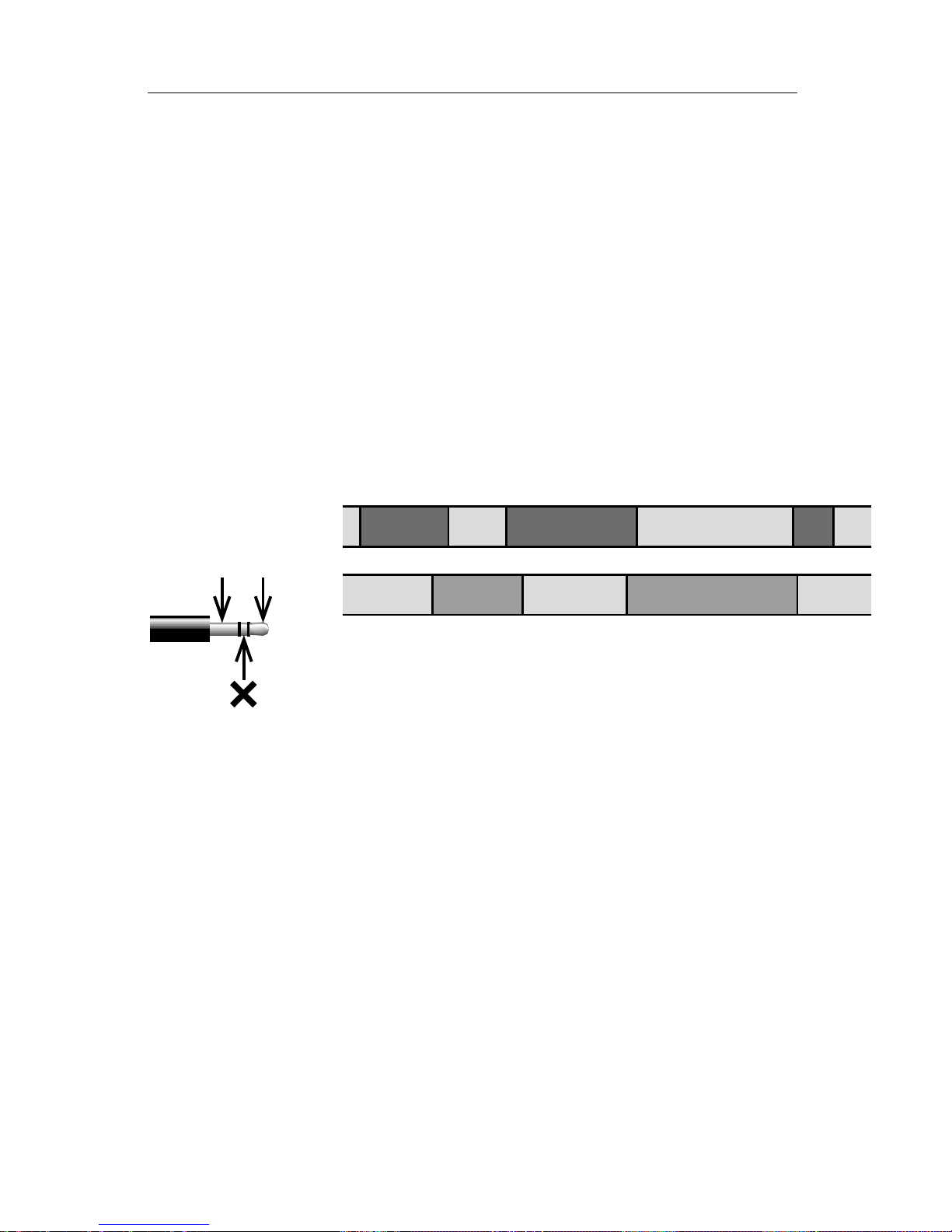
VIDEONICS DIGITAL VIDEO MIXER PAGE 71
A/B Roll Editing
The most complex case is editing scenes from multiple sources. In this
case, it is the job of a device called an A/B roll edit controller (or your job, if
you’re doing it manually) to synchronize the sources so they are correctly
timed. It’s also your job, while shooting or when making working copies, to
make sure any two scenes you plan to use for transitions are on different
tapes — you can’t wipe from scene 1 to scene 2 if both are on the same tape.
Typically, you would record a countdown before each scene so you know
when it will start and back-time the transitions accordingly. Example: Scene 1
is playing on VCR A. You know it ends soon so you start VCR B. You pause B
at a point 5 seconds before its action begins. When A is 5 seconds from its end,
you release B. Now both are rolling and at the right instant, you perform the
transition. This is what an A/B roll edit controller does.
Another method involves the use of working copies. You copy your
original footage to new tapes, placing every other scene on a different tape.
The net result would look like this:
1
2
3
4
5A
B
Scene 1 is on tape A, scene 2 is on tape B, etc. The scenes
are laid down accurately so that both tapes can simply roll
from the beginning and as a scene is about to end, the next
scene will be available. When a transition will be used be-
tween scenes, the scenes are overlapped accordingly.
The advantage of this method is that it makes it easy to get exactly what
you want on tape. It has two disadvantages: It requires careful planning and
organization; and it requires an extra “generation” — productions are a copy
of a copy rather than a copy of the original.
Titles
As explained in Chapter 4, “Connecting Editing Equipment,” a title generator capable of superimposing titles on video can be connected between the
Mixer’s output and the Record VCR. Titles can be superimposed over the
output, including transitions.
Here’s an example using the Videonics TitleMaker. Set up a number of
titling pages. Between each page, set up a blank page (a page with no titles
and the background set to plain video). While a blank page is displayed, the
output is unaffected. Press PLAY on the TitleMaker and the next page of titles
will appear, superimposed over the Mixer’s output. You can perform a
transition and the titles will continue to be superimposed as the transition
occurs.
Page 77

PAGE 72 VIDEONICS DIGITAL VIDEO MIXER
Additional TitleMaker features, such as tinted backgrounds, patterns,
scroll, and crawl, can all be used. Because the Mixer’s TBC creates a stable
time base, the TitleMaker will be able to lock solidly to it, for an excellent
picture.
Title generators of lesser quality can be used instead on one of the Mixer’s
inputs. Chroma key can be used to superimpose the titles onto another
source. To do this, you would set the titler to create titles atop a solid color
background and key over that color, so the second source’s video would
replace the background color.
Other Accessories
The Mixer is compatible with external audio mixers, video processors, and
more. Chapter 4, “Connecting Editing Equipment” describes ways to hook
up and use such accessories.
GPI Trigger
Advanced feature. The Mixer is equipped with a jack marked “CONTROL
(GPI).” This jack will accept a GPI (“General Purpose Interface”) trigger from
an external source such as a pushbutton switch or an edit controller with GPI
output.
A GPI pulse causes the Mixer to behave exactly as if the PLAY button were
pressed. Generally, it will start a transition that you have previously set up. If
you have learned a sequence (Chapter 17, “Sequences”), it will trigger the
next transition in the sequence.
Cables for connecting the CONTROL input are not generally available but
if you are reasonably handy with simple wiring, you can make your own. It’s
not a difficult job but note the warnings below. If you have any misgivings
about making this cable, enlist the aid of a qualified technician.
Use a 3.5 mm stereo (3 wire) phone plug (the type used for portable
headphones). Do not use a mono jack as it will short out two of the CONTROL connections. Connect wires to the tip and ground. Leave the middle
(“sleeve”) section unconnected. The other ends of the two wires go to the
controlling device.
You can use an ordinary pushbutton to remotely trigger the Mixer —
simply wire a normally-open switch to the two wires. An edit controller or
computer that provides a contact closure will also operate as a trigger.
Important: Do not connect a power source of any kind to the CONTROL
input. This can damage the unit and void the warranty.
Automatic Input Scan Mode
The Mixer can be used to make a simple scan of all the inputs. This is a
convenient way to monitor multiple sources such as security cameras or
multiple satellite feeds.
Page 78

VIDEONICS DIGITAL VIDEO MIXER PAGE 73
Automatic scan mode presents a full screen view of each input in turn on
the OUTPUT monitor. The scan starts with A and proceeds with B, C, and D,
then repeats the sequence. Each is displayed for about two seconds. The
switch between sources in not synchronized and may cause the screen to
jump or roll. Only sources that have video connected are included in the scan.
The PREVIEW screen continues to carry the normal preview while the scan is
presented on the OUTPUT monitor.
To begin an input scan, press SHIFT and FADE/DISSOLVE at the same
time. Press any button to end it.
Page 79

PAGE 74 VIDEONICS DIGITAL VIDEO MIXER
Chapter 20 •Chapter 20 • Video Quality
Video Scaling Artifacts
When a video image is reduced in
size, some picture information must
be discarded because the picture is
displayed using a smaller number of
pixels (picture dots) than normal. One
aspect of this is that small details may
be missing as pixels are removed.
Lines may become slightly jagged as
the picture is reduced and portions
of the line are removed to accomplish the reduction in size. When a
picture is being scaled down gradually, as in some transition effects,
small features may appear and disappear as the pixels that contain them
are successively included or excluded.
All these effects are normal when
performing advanced effects and are
quite minor, especially when the transition is performed at normal speeds.
Slide/Compress Motion
Effects
Depending on the relative timings
of the input signals, a thin black stripe
may separate the two images when
you use an effect that includes a compress or slide. Its width may vary as
you perform the effect manually.
Freeze Quality
The Mixer’s freeze function is a
“field freeze.” It captures one field
(half a video frame) and duplicates it
to make the two fields that comprise
a frame. The advantage of a field
freeze is that it eliminates flashing
The Digital Video Mixer is
designed to meet the highest video
standards. A number of video artifacts can be created, especially
when fancy video effects are in
use. This chapter describes common artifacts.
Note: This chapter discusses advanced video concepts.
Preview Image Quality
The preview images in the PREVIEW screen are designed to monitor the action and don’t match the
Mixer’s normal quality. They also do
not show input effects or the results
of the advanced setup options. Depending on what type of sources are
connected, there may be occasional
lines appearing alongside the preview
images. This is especially likely when
you use cue or review (search) with a
VCR or camcorder connected to an
input.
However, note that:
• The quality of the preview images
has no effect on the video output
quality.
• You can switch to a full-size, full
frame-rate version of the NEXT or
CURRENT source at any time by
pressing the DISPLAY button. (The
DISPLAY button causes the PRE-
VIEW monitor to alternate be-
tween the normal PREVIEW
screen, the NEXT source, and the
CURRENT source.)
Page 80
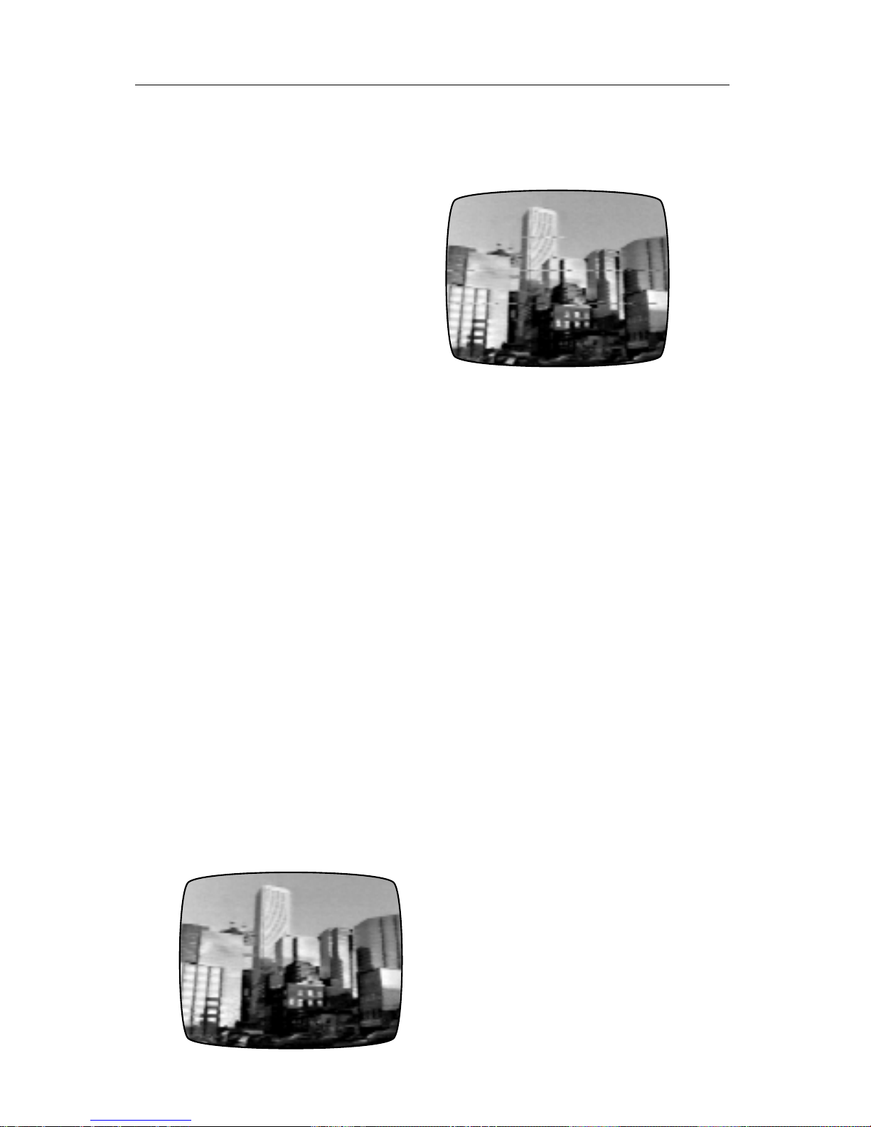
VIDEONICS DIGITAL VIDEO MIXER PAGE 75
caused when an object is in a different position in the two captured fields or
when an object is so small it appears in only one field. The Mixer’s field freeze
eliminates flashing artifacts but reduces vertical resolution since it only
shows one field.
Upside-Down Video
When video is flipped upside
down (as it is for some transition effects or if you use the vertical flip
option on the Input Effects screen),
the picture resolution is reduced
slightly and the frame rate is reduced
to make the video image more stable.
The reduction is subtle with most
video and most effects, especially
those that move quickly.
Video Processing Artifacts
Video processing circuits such as
enhancers, sharpness controls, and
the playback circuitry used in some
VCRs, can over-process the video
causing the visible signal to interfere
with the invisible sync portion of the
signal, making the signal non-standard. This may cause video lines to
shift to the right, black lines to enter
the picture area from the left edge of
the screen, white flashes, video “tearing,” or a shredded picture.
Normal Picture
Picture with Video Tearing
The best solution is to reduce or
remove the processing, bringing the
signal back to normal. VCRs and
camcorders often have controls that
can disable extra processing. If your
VCR or camcorder has a SHARPNESS
control, set it to zero or off. If there is
an EDIT switch turn it ON.
If the processing cannot be disabled, you can compensate using the
MX-1’s special “filter settings.” The
Advanced Setup section of Chapter
5, “Setup Screen,” describes this.
Page 81

PAGE 76 VIDEONICS DIGITAL VIDEO MIXER
Chapter
21 •21 • Specifica-
tions
BASIC FEATURES
4-input switcher, digital frame synchronizer and
special effects mixer with dual time base
corrector.
EFFECTS
Video: 210 dissolves, wipes, slides, compress/
expand, fly-in, flips, zooms, luminance key, more
(see list). Manual or automatic at 10 speeds.
Input effects include black and white, negative
(black and white and/or color), horizontal and
vertical flip, mosaic, strobe, film-look strobe,
paint/posterization, solarization. Can be
combined.
Special effect modes include compose, picturein-picture, chroma key, stop action (snapshot).
Audio: Mix, fade, audio-follows-video or
separate control.
COLOR GENERATORS
2 (background and border), 1440 colors.
OTHER FEATURES
LEARN mode stores up to 25 transition effects.
Preview display shows all four inputs.
Color bar generator, black burst, color genera-
tors.
Field freeze.
GENERAL SPECIFICATIONS
Power: 12 VAC, 1A. 120 VAC, 60 Hz adapter
included in US/Canada. (Other supplies available
in other areas.)
FCC/UL/CSA approved (non-US/Canada
versions meet local regulatory standards).
Dimensions: 12 x 9.5 x 3.9" (300 x 165 x 99
mm).
Weight: 4 lbs. (1.8 kg).
Ambient temperature: 32-104°F (0-40°C).
Ambient humidity: Less than 90%.
INPUTS
VIDEO: 4 x S-video (Y/C): Y=1 Vp-p, C=0.30 Vpp, 75-ohm, 4-pin mini-DIN connectors.
4 x composite (RCA): 1.0 Vp-p 75-ohm, RCA
connectors.
AUDIO: 6 x RCA connectors, 15 k ohms.
GPI: Mini-jack.
OUTPUTS
VIDEO (PREVIEW and MAIN): 2 x 1.0 Vp-p, 75
ohm, RCA connectors.
S-VIDEO (MAIN): Y=1.0 Vp-p, C=0.3 Vp-p; 75
ohm, 4-pin mini-DIN connector.
AUDIO (L and R): 1 k ohms, RCA connectors.
HEADPHONE: Stereo jack, 8-100 ohms, mono
signal.
VIDEO PERFORMANCE
Meets FCC broadcast specifications.
Digital conversion: 13.5 MHz, 4:2:2, 8-bit
quantization, 4 X subcarrier oversampling.
Dual-field infinite-window time base corrector.
Time base meets RS-170A standard.
Compatible with all NTSC videos sources and
tape formats. (PAL version available.)
Gain: Unity.
S/N Ratio: 56 dB
Resolution: 5.0 MHz
AUDIO PERFORMANCE
Frequency response: 20 Hz-20 kHz, ± 3 dB.
S/N ratio: 56 dB.
Page 82

VIDEONICS DIGITAL VIDEO MIXER PAGE 77
Chapter
22 •22 • Glossary
A/A (OR A/X/A) ROLL EDITING
Editing from a single source, using effects to transition from the source to itself (source “A” to “A”)
using a picture freeze at the end of one scene to
transition the start of the next scene.
A/B ROLL EDITING
Editing from two source VCRs (“A” and “B”) to a
third record VCR. Typically, a mixer, such as the
Digital Video Mixer, is used to provide transition
effects when moving between sources. Control
over the machines and process can be done manually or automatically using an edit controller.
AUDIO
The “other half” of any video production — the
“soundtrack” of a videotape. Audio can consist of
native sound (the sound recorded on the original
tapes) or added sound, such as background music and narration.
AUDIO-FOLLOWS-VIDEO
During video recording, the video signal is usually
accompanied by an audio signal. Sometimes, during video editing, when images from several cameras or VCRs are switched, the audio signal is
separated from the video signal. Audio-followsvideo mixers process both audio and video, and
may be set so that the accompanying audio will
“follow” the video when switched from one video
source to another. If desired, the audio may be
selected from a different source than the current
video source. The Digital Video Mixer allows either audio-follows-video or separate audio selection functions.
AUDIO MIXING
The blending of two or more audio signals to
generate a combined signal. During video editing,
audio mixing may be used to insert a voice-over
or background music.
BLACK BURST
A composite color video signal comprised of sync
and color burst signals and black video. Black
burst generators are used in video studios to “lock”
the entire facility to a common signal (house sync).
BNC CONNECTOR
A type of connector with cable locking capability,
used on some VCRs, video and RF equipment.
The BNC connector is suitable for use where high
frequency, high reliability signals are involved.
BORDER
The boundary between two merged video pictures, as created with chroma key or wipe effects.
Bordering is a special effect which is sometimes
used to alter the border from a sharply defined
line to a soft blend of the two images or to a
colored line. The width and texture of the border
can often be changed.
CAMCORDER
Combination of camera and video tape recorder
in one device.
CHARACTER GENERATOR
Device used to superimpose text onto a video
signal. The Video TitleMaker is an example of a
full-featured character generator.
CHROMA
The color information contained in a video signal,
consisting of hue (phase angle) and saturation
(amplitude) of the color subcarrier.
CHROMA KEY
The process of overlaying one video signal over
another by replacing a range of colors with the
second signal. Typically, the first (foreground) picture is photographed with a person or object
against a special, single-color background (the
key-color). The second picture is inserted in place
of the key-color. The most common example is in
broadcast weather segments where pictures of
the weather map are inserted “behind” the weather
person. The Digital Video Mixer includes chroma
key.
COLOR BARS
An electronically generated video pattern consisting of specific colors, used to establish a proper
color reference before recording and playback
and for adjustment purposes.
COLOR PROCESSING
A way to alter a video signal to affect the colors.
The Video Equalizer includes a color processor
capable of color correction.
COMPOSE
A feature which allows still images and colored
rectangles, borders, and lines to be combined
with a solid color or moving video background to
make an on-screen composition.
COMPOSITE VIDEO
A video signal in which the luminance (black and
white), chrominance (color), blanking pulses, sync
pulses and color burst information has been combined. NTSC, PAL, and SECAM are composite
video standards. RCA-style jacks are often used
for composite video signals.
CONTRAST
The range of light and dark values in a picture or
the ratio between the maximum and minimum
brightness values. When contrast is high, the picture contains stark blacks and whites. When low,
the picture shows more variations of gray tones.
CONTROL-L (LANC)
A form of edit control common on 8-mm and Hi8
VCRs and camcorders and on some VHS and
Super-VHS units. See EDIT CONTROL.
Page 83

PAGE 78 VIDEONICS DIGITAL VIDEO MIXER
CROSS COLOR
This phenomenon manifests itself as spurious onscreen rainbow patterns on highly textured objects similar to those found on a striped shirt or
tweed jacket.
CROSSFADE
The audio equivalent of the video dissolve where
one sound track is gradually faded out while a
second sound track simultaneously replaces the
original one.
dB (Decibel)
A unit for expressing the ratio of two amounts of
electric or acoustic signal power. Technically, this
is equal to 20 times the common logarithm of the
voltage or current ratio.
DIGITAL
A method of representing a signal using binary
numbers. The Digital Video Mixer converts video
signals into digital form and all video processing
is done digitally. Digital video provides advantages in reliability, accuracy, quality, performance,
and features.
DISSOLVE
A process whereby one video signal is gradually
faded out while a second image simultaneously
replaces the original one.
DUB
A duplicate copy made from one recording medium to another.
DVE (Digital Video Effects)
These effects are found in special effects generators which employ digital signal processing to create two or three dimensional wipe effects. DVE
generators are getting less expensive as the kind
of effects they create get more popular. The Digital Video Mixer includes such effects.
8-MM VIDEO
A consumer video record/playback system, developed by Sony and others, utilizing 8-mm wide
magnetic tape.
EDIT CONTROL
A connection on a VCR or camcorder which allows direct communication with external edit control devices. LANC (Control-L) and Panasonic 5pin are common consumer edit control protocols.
Thumbs Up and Video EditMaker work with both
of these control formats as well as machines lacking direct control.
EIA RS-170A
Broadcast time base specification describes how
accurately the video signal is timed. Fully supported by the Digital Video Mixer.
FADING
1. The intensity of a video picture is deliberately
diminished until it becomes totally black (fade to
black). Both the Thumbs Up and the Digital Video
Mixer offer fade effects. The term is also sometimes used for a dissolve.
2. An audio fade is a decrease in the sound level
until it is no longer audible. Audio fading is often
used in conjunction with video fading causing the
sound and image to fade simultaneously. (See
AUDIO-FOLLOWS-VIDEO)
FIELD
One-half of a complete television picture. Two
fields make up a complete television picture frame.
NTSC signals show 60 fields per second. PAL
and SECAM show 50. (See FRAME, INTERLACE)
FRAME
A complete video image consisting of 2 fields.
Also used to describe the total visible area of a
video image. NTSC signals show 30 frames per
second. PAL and SECAM show 25.
FRAME RATE
The speed with which video frames are presented.
A full frame rate NTSC picture shows 30 frames
per second. A PAL or SECAM picture shows 25.
Some devices will show an image at reduced
frame rate in which frames are skipped. The resulting images are fine for preview purposes but
action will be choppy compared to full frame rate
images.
FRAME SYNCHRONIZER
A digital electronic device which synchronizes two
or more video signals. A frame synchronizer uses
one of its inputs as a reference and locks the
other video signals to the reference’s sync and
color burst signals by delaying the other signals
so that each line and field starts at the same time.
Signals synchronized in this manner can be mixed
using dissolves, wipes, and other effects. A frame
synchronizer’s output is only as good as the reference source unless a TBC is used (see TBC). The
Digital Video Mixer includes this feature plus a
TBC.
FREEZE
A process which allows you to “catch” and freeze
one on-screen TV/video field or frame. Digital
devices do this by storing the picture in digital
memory. It is possible to freeze either one field or
a whole frame. A field freeze has half the picture
resolution of a frame freeze but is often more
stable because it eliminates subject movement
that occurs between one field and the next.
Digital freeze frame is one special effect that can
be created with a special effects generator or a
TBC. The Digital Video Mixer includes this feature.
GENERATION
The number of duplication steps between an original recording and a given copy. A second generation duplicate is a copy of the original and a third
generation duplicate is a copy of a copy of the
original.
GENERATION LOSS
Video quality lost with each successive generation as tapes are copied.
Page 84

VIDEONICS DIGITAL VIDEO MIXER PAGE 79
GENLOCK
Creation of a video signal that is synchronized to
a reference signal. Because the new signal is
synchronized, it can be superimposed on the original signal and effects, such as dissolves, can be
performed. Name comes from “GENerating a
LOCKed signal.”
HI-8
A high-resolution video format based on the 8mm format. Similar in performance to S-VHS in
many respects but using 8-mm wide videotape.
HUE
Often used synonymously with the term tint. It is
the dominant wavelength which distinguishes a
color such as red, yellow, etc.
INTERLACE
A system developed for television which divides
each video frame into two fields. This is done by
first drawing one field consisting of an image’s
odd scan lines and then drawing the remaining
even scan lines, interweaving both fields. Interlacing greatly reduces flicker.
KEY
Replacement of parts of one video image with
another, based on color or brightness of the original picture. See CHROMA KEY and LUMINANCE
KEY.
LANC
See CONTROL-L
LINE
A video picture consists of an array of horizontal
lines. An NTSC frame has about 525 lines, a PAL
frame has about 625.
LUMINANCE
A video signal is comprised of luminance, chrominance (color information) and sync. Luminance is
the measure of brightness of a video image. If
luminance is high, the picture is bright and if low
the picture is dark. Luminance is the black and
white portion of the picture.
LUMINANCE KEY
Replacement of portions of one picture with another, based on brightness. The brightest portions
are replaced while the dark portions are unchanged
(or vice-versa) and in-between values are mixed
proportionately.
MIXER, AUDIO/VIDEO
1. An audio mixer allows multiple audio sources
(microphone, CD player, VCR, etc.) to be combined, or mixed, to produce a sound track.
2. A video mixer combines multiple video sources,
allowing various effects (such as dissolves and
wipes) to be used to transition from one source to
another. A frame synchronizer is incorporated in a
video mixer to allow two videos to share the screen
at once.
MONITOR
A television that gets its signal directly from a
camera or VCR.
NEGATIVE
The conversion of a video picture to a negative
image. Blacks and whites are reversed while colors are inverted. For example, red becomes a
bluish tint, green becomes purple, etc.
A negative effect can be performed on the luminance (black and white) portion of the image, the
chrominance (color) portion, or both. The Digital
Video Mixer includes both color and black and
white negative effects.
NOISE
A general term used in electronics to indicate any
unwanted random, electrical signal, unrelated to
the original signal. Video noise is manifested as
snow, graininess, ghost images or picture static
induced by external sources such as the national
power-line grid, electric motors, fluorescent lamps,
etc.
In audio, noise is manifested as hiss and static.
NONLINEAR EDITING
The process of editing using instantaneous retrieval (random access) computer controlled media such as hard disks, CD-ROMs and laser discs.
NTSC (National Television Standards Committee)
Standard of color TV broadcasting used mainly in
the United States, Canada, Mexico and Japan,
featuring 525 lines per frame and 60 frames per
second. (See PAL and SECAM)
OUTPUT
Similar to the preview in concept except that the
resulting output is the final signal which goes “on
the air.” Also called “program out.”
PAINT
Special effects in which the normal wide range of
colors and brightness levels in a video image are
reduced to a small number of colors or luminance
levels. Fine graduations of color and brightness
are removed. The result is sometimes described
as an oil painting effect and is available on some
special effects generators. Also called
POSTERIZATION and sometimes (erroneously)
SOLARIZATION. Both the Video Equalizer and
Digital Video Mixer include this effect.
PAL (Phase Alternate Line)
The European color TV broadcasting standard
featuring 625 lines per frame and 50 frames per
second. (See NTSC and SECAM)
PIP (Picture In Picture)
A digital special effect in which one video image is
inserted within another allowing several images to
share a single screen. (Also called video compress).
POST-PRODUCTION
All editing done after the video footage has been
recorded. Editing, titling, special effects insertion,
image enhancement, enriching, fine tuning and
other production work is done during post-production.
Page 85

PAGE 80 VIDEONICS DIGITAL VIDEO MIXER
Page 86

VIDEONICS DIGITAL VIDEO MIXER PAGE 81
POSTERIZATION
See PAINT.
PREVIEW
An output that allows the operator to see the
video source before processing (before titles are
added, effects are performed, etc.) Typically, each
signal can be previewed on its own monitor. This
is an effective method to check work before going
“on the air.” The Digital Video Mixer includes a
separate preview output which can be used to
preview all four of its video input signals on-screen
simultaneously.
PRIMARY COLORS
The basic colors used in TV and video systems of
red, green and blue.
PROGRAM
See OUTPUT.
RCA CONNECTOR
A type of connector used on consumer VCRs and
camcorders. The RCA connector is typically used
for short composite video and audio.
RC TIME CODE (Rewritable Consumer)
A system for reading/writing time code. Supported
by both the Thumbs Up and Video EditMaker.
RESOLUTION
A measure of the ability to reproduce detail. Generally, referred to as horizontal resolution and
evaluated by establishing the number of horizontal lines which are clearly discernible on a test
pattern.
RF (Radio Frequency)
A term used to describe the radio signal band of
the electromagnetic spectrum (about 3 MHz to
300 GHz). Broadcast television is RF, carried by
RF or antenna cable. VCRs include an RF jack in
addition to the separate VIDEO and AUDIO jacks.
RF MODULATOR
Device that combines video with an RF source so
the result can be transmitted to a television or
VCR. Converts a VIDEO and AUDIO jack to an
RF jack.
RGB (Red/Green/ Blue)
The basic components of a color video signal.
SCART
Multi-pin audio/video connector used in consumer
equipment, especially in Europe.
SECAM (Sequential Couleur A’memorie)
The video standard used mainly in France, Eastern Europe, Russia and surrounding countries. In
countries using the SECAM standard, most video
production is done using PAL and converted to
SECAM prior to transmission. MESECAM is a
very similar format used in some Middle East
countries. (See NTSC and PAL)
SEG (Special Effects Generator)
Device designed to generate special effects. The
simplest devices process a single video signal,
change its color, generate sepia tones, invert the
picture to a negative, posterize the image and
fade or break up the image into various patterns.
More sophisticated equipment, such as the Digital
Video Mixer, can combine several video sources,
and perform digital effects.
SEPIA TONE
A process used in photography to generate a
brownish tone in pictures giving them an “antique”
appearance. The same idea has been electronically adapted for video production where a black
and white image can be colored in sepia.
SIGNAL-TO-NOISE RATIO (S/N)
The ratio in decibels (dB), of an audio or video
signal, from the signal’s maximum peak-to-peak
voltage to the measured voltage in absence of a
signal.
In video, the higher the ratio, the less snow is
visible. In audio, the higher the ratio, the cleaner
the sound.
SMPTE-VITC
A version of VITC.
SNOW
A general term used to describe interference in a
video image. It manifests as random colored or
black and white dots.
SOLARIZATION
An effect in which the brightest portions of a picture become negative (the lightest parts become
darker but the dark and middle tones are unchanged).
SPECIAL EFFECTS
Artistic effects added to a video production in
order to enhance a production. Special effects
may vary from the limited addition of patterns or
the mixing of several video images together, to
sophisticated digital effects such as picture compression, page flipping and three-dimensional effects. Special effects are usually created using
SEGs such as those included in the Video Equalizer, Video TitleMaker and Digital Video Mixer.
SPLIT SCREEN
An electronic process which allows the viewing of
two video images, side by side or above and
below, on-screen simultaneously.
STEREO MIXING
Simultaneous processing of both left and right
audio channels.
Page 87

PAGE 82 VIDEONICS DIGITAL VIDEO MIXER
SUPERIMPOSE
To place in front of video, e.g., placing text over a
video signal.
S-VHS (Super-VHS)
High resolution version of the VHS videotape format.
S-VIDEO
Abbreviation for Super-Video, this term describes
a video system which transmits the chrominance
(color) and luminance (black and white) information over separate conductors to minimize color
fringing, dot crawl, and other artifacts of color and
black and white interaction.
SWITCHER
General term for a device used to select different
signals (audio, video or RF) from various sources.
Typically, a switcher’s output is then routed to a
monitor or recorder.
SYNC (Synchronization)
A term used in electronics to describe the precise
alignment of two signals or functions. Sync is an
essential element of video signals. The sync rides
in an invisible portion of the video signal. It contains pulses that mark the start of each line, field,
and frame.
A frame synchronizer matches two video signals
so they are in sync. A TBC matches signals and
also matches them to an electronic reference, to
improve video quality.
TALENT
A term used to refer to on-camera subjects in a
video production.
TBC (Time Base Corrector)
A device used to rectify any problems with a video
signal’s sync pulses by generating a new clean
time base and synchronizing any other incoming
video to this reference. The Digital Video Mixer
includes a TBC.
TIME CODE
A digital code number recorded onto a videotape
for editing purposes. When decoded, the time
code identifies every frame of a videotape in
hours:minutes:seconds and frames. Two common
time code systems used for video are SMPTEVITC and RC (consumer).
TITLING
The addition of text to a video image. Titles may
be added to a video scene during shooting or in
post-production. Sophisticated titling devices, such
as the Video TitleMaker, allow the user to prepare
text and graphics in various sizes, fonts and colors to be triggered later, one-by-one, at appropriate places within a production.
VITC (Vertical Interval Time Code)
VITC is the most popular method for recording
and reading time code onto videotape. The time
code is inserted into the vertical interval (the vertical blanking retrace period) of the video signal,
where it is invisible on-screen yet easily retrieved,
even when a helical scanning VCR is in pause
mode. The Thumbs Up editor supports VITC and
RC time codes while the Video EditMaker supports a Videonics proprietary VITC and standard
RC time codes.
VHS (Video Home System)
Consumer video record/playback format using 1/
2” width magnetic tape.
VHS-C
A standard VHS system utilizing a compact cassette shell, reducing recording time while allowing
the tapes to be played by standard VHS equipment via an adapter cartridge.
VIDEO BANDWIDTH
The range between the lowest and highest signal
frequency of a given video signal. In general, the
higher the video bandwidth, the better the quality
of the picture.
VIDEO EDITING
A procedure for combining selected portions of
video footage in order to create a new, combined
version. A variety of editing consoles are available. During video editing, special effects such as
wipes, dissolves, inserts, etc. can be added. Professional editing is done using time code recorded
on every frame of the magnetic tape allowing
single frame accuracy. Audio editing is often carried out simultaneously with video editing. The
Thumbs Up and Video EditMaker offer versatile
solutions for any editing application.
VIDEO MIXER
A device used to combine video signals from two
or more sources. Inputs are synchronized, then
mixed along with various special effects patterns
and shapes. The Digital Video Mixer is capable of
handling up to 4 video inputs and includes a TBC.
WIPE
A process in which one image is electronically
“wiped” off the screen and replaced by another.
Special effects generators provide numerous wipe
patterns varying from simple horizontal and vertical wipes to multi-shaped, multi-colored arrangements. The Digital Video Mixer includes this effect.
Y/C
The separation of video into separate luminance
(Y) and chrominance (C) signals. Also called Svideo. All Videonics video products support the
(Y/C) format.
Page 88

VIDEONICS DIGITAL VIDEO MIXER PAGE 83
Chapter
23 •23 • Effects
List
Terms and Abbreviations
(A): The CURRENT source (the one on the screen
before the transition begins).
(B): The NEXT source (the one on the screen after
the transition is complete).
Dissolve: One image fades away as another fades
in.
Wipe: A wipe is a simple window or boundary that
reveals the underlying video. The video image neither moves nor changes size.
Slide: A slide leaves the video full size but the
picture moves with the transition.
Comp., Exp.: (Compress,Expand): The video is
resized to fit in the window — generally the entire
picture will be scaled to fill the window.
H, V: (Horizontal, Vertical): These refer to the direction the transition moves. For example, a V wipe
is a horizontal line that moves vertically up or
down the screen. When the effect runs in the forward (non-reversed) direction, vertical transitions
move down the screen and horizontal transitions
move from left to right, unless otherwise indicated.
CW: Clockwise • CCW: Counter clockwise
L: Left • R: Right • Ctr: Center • T: Top • B:
Bottom
TLC: Top Left Corner • TRC: Top Right Corner •
BLC: Bottom Left Corner • BRC: Bottom Right
Corner
“;” divides multi-step transitions. “/” indicates
two actions that occur at once.
* Transitions with * always use fixed direction
when performed from frozen picture. They are not
affected by REVERSE button.
# Transitions with # operate differently when performed from a frozen picture. Simpler effects are
automatically substituted.
“Top 30” Effects
The “Top 30” symbols, numbers 0-29, are the
ones that appear on the PREVIEW screen when you
first turn the Mixer on. They represent 30 commonly used effects. They are duplicated elsewhere
in the effects list, near related effects. The “=”
column shows the effect’s other location.
NO. = DESCRIPTION
0 - Cut
1 160 Dissolve
2 30 H Wipe
3 70 V Wipe
4 40 H Curtain Wipe (B) from Ctr to full
5 81 V Curtain Exp. (B) from Ctr to full
6 35 H Slide (A)/Exp. (B)
7 38 H Slide (A)/Slide (B)
8 74 V Comp. (A)/Exp. (B)
9 78 V Slide (A)/Slide (B)
10
#
56#H Slide (A) out L; Slide (B) in from L
11* 66* H Comp. (A) R to 1/2 screen slice;
Slide to L; slide under Ctr line
12 171 Ctr Exp. (B)
13 161 Ctr Exp. & Dissolve (B)
14
#
188#Comp. (A) to lower R of (B); Exp. (B)
15
#
184#H Comp. (A) alongside (B) in mo-
tion; Exp. (B)
16 180 Comp. (A) to 1/2; roll R to (B); Exp.
17 114 Slide in slice (B) from L at T; Wipe
slice to full
18 227 V Comp. (A) to Ctr slice; H collapse
slice to Ctr point
19 212 Butterfly from T L/random proportion
20 210 Ctr Exp. (B) with 2 flips
21 222 Ctr Comp. (A); swing back; out B
22 193 Bounce off edges/Wipe
23 190 Bounce in from T
24* 200* Comp. (A) to T; CW spiral out to T
25* 208* Comp. (A); CW spiral to Ctr
26
#
221#Mosaic Zoom
27 216 Random Sizes & Flips (B)
28 237 Luminance Key 1
29 234 Checkerboard w/middle dissolve
Page 89

Front panel buttons and
rear panel connector
labels are indicated by
upper-case entries (such
as FREEZE).
A
A/A roll 3, 68
effects 69
freeze 69
A/A roll editing 68
A/B roll editing 69
A/X/A roll 3, 68
ABCD buttons 31
advanced setup 22
AGC 23
applications 67
arrow (REVERSE) 35
arrow keys 8, 32
compose 58
artifacts 72
audio 3, 36
connecting 16
audio connections 11
audio control 3
audio follows video 37
audio inputs
connecting 16
AUDIO light 36
audio mixer 3, 19, 38
audio mixing 19
audio out 14
audio specifications 74
AUDIO/VIDEO 36
auto-reverse 35
auto-take 33
automatic connection 20
automatic input scan
mode 71
automatic transitions 33
B
BACK COLOR 7, 39
backdrop 48
background 48
chroma key 48
compose 58
picture-in-picture 54
solid color 39
background color 6, 39
backgrounds 7
basic concepts 1
basic controls 25
big effect buttons 9
big transition effect
buttons 33
black and white 44
black burst 52
black level 23
black lines 73
Index
blue, chroma key 46
blue highlight
6, 25, 26, 32
BNC connections 11
border
compose 60
turning on and off
40
BORDER COLOR
7, 39, 40
border color 6
borders 7, 39
built-in demo 25
buttons 5
C
cable
BNC 11
composite 11
RCA 11
RF 11
S-video 11
Y/C 11
cable types 11
cables
audio 11
Y-cable 11
character generator
19, 70
chroma AGC 23
CHROMA KEY 48
chroma key 3, 46
background 48
color 47
fine-tuning 49
foreground 48
hints 47
lighting 47
performing 48
setup 47
sources 48
titles 70
transition to/from 50
closed captioning 65
color
background 39
border 39
chroma key 48
defining 40
user-defined 40, 41
color backgrounds 7
color bars 52, 57
color correctors 18
color generator 53
color negative 44
colors
choosing 39
specifications 74
COMPOSE 58
compose 3, 57
background 58
placing elements 59
positioning and
sizing elements 58
composite 20
composite connections
11
compress 81
connecting sources 15
connections
audio 11
BNC 11
composite 11
editing equipment
18
overall concept 10
RCA 11
RF 11
S-Video 11
Y-cable 11
Y/C 11
connectors 5
CONTROL 19, 71
CONTROL (GPI) 15
controls 5
CURRENT source
6, 8, 26, 30, 31, 34
changing 31
CUT 6, 31
CUT buttons 26, 28
cut effect 28
cuts 28, 30, 68
cutting back and forth 28
D
defaults 20
DEMO 5, 25
demo 5, 25
dimensions 74
direction 6, 35
DISPLAY 26, 27, 43
dissolve 81
dissolves 30
dual TBC mode 64
dual-field TBC 66
E
edit control 19
edit controller 4, 19
EDIT switch 16
editing 4, 67
A/A roll 68
A/B roll 69
multiple source 69
single-source 68
synchronizing 67
editing equipment 18
connecting 18
effect buttons 9
effect symbols 32
effects 30, 42
choosing 32
more 51
effects generator 3
effects list 81
elements
compose 57
enhancers 18, 73
erase
compose 60
executing transitions 33
expand 81
F
fast dissolve 29
features 74
field freeze 45, 73
fields 52
film look 44, 52
filter 23
fine-tuning
chroma key 49
flashes 73
flashing light 26
flip horizontal 44
flip vertical 44
flips 30
fly-ins 30
foreground
chroma key 48
compose 58
picture-in-picture 54
frame freeze 45
frame rate 26, 44, 64
frame rate lock 23, 64
frame synchronizer 2
frames 52
FREEZE
33, 35, 45, 55, 59, 68
freeze 45, 55, 73
front panel 5
frozen picture 35, 45
G
General Purpose Interface
71
generation 70
GPI 15, 19, 71
green, chroma key 46
green highlight
6, 7, 8, 31
H
headphone symbol 36
headphone volume 23
headphones 15
holes
compose 57, 60
horizontal flip 44
humidity 74
Page 90

I
IN 3 audio 21
IN and OUT 13
independent audio 37
indicators
sound source 36
infinite-window TBC 66
input effects 42
choosing 42
list 44
single-source
editing 69
INPUT F/X 42
input monitors 17
input routing 21
input scan mode 71
input selection switch 14
inputs 5
installation 5, 10
IRE 23
J
jacks 5
audio 11
BNC 11
composite 11
RCA 11
RF 11
S-video 11
Y/C 11
K
key-colors 48
keying 46, 51
L
large effect buttons 9
large transition effect
buttons 33
learn 61
steps 62
learning a sequence 61
light
flashing 31
steady 31
lights 26
AUDIO/VIDEO 36
LINE 14
line 59
lines 73
compose 57
live mixing 67
live video production 3
lock 23, 64
luminance key 3, 51
M
manual control 8
manual execution 34
manual transitions 33
mixer 2
mixer basics 2
mixing sound 38
monaural 11, 15
monitor input switch 14
monitors 12
connecting 14
input 17
mono 11, 22
mosaic 44
movie 44
multiple cameras 3
multiple monitor setup 12
multiple source editing
69
multiple-source
production 3
N
native sound 37
negative 44
newsletter 1
NEXT source
6, 7, 26, 30, 31, 34
changing 31
no audio 22
noise filter 23
number keys 9, 32
O
one-way reverse 35
output
connecting 14
OUTPUT monitor
10, 11, 12
output specifications 74
output sync 66
outputs 5
P
paint 44
performance 74
performing transitions 8
picture freeze 45
picture tearing 23
picture-In-picture
background 54
foreground 54
picture-in-picture 2, 54
sizing window 55
sources 54
window 54
PIP 2, 54
PLAY 8
PLAY (AUTO-TAKE) 33
playing a sequence 62
posterization 44
power 74
POWER input 13
power light 5
power supply 5, 13
POWER switch 13
PREVIEW connection 15
preview image quality 72
preview images 6, 25
PREVIEW monitor
6, 10, 12
connecting 15
Preview monitor 11
PREVIEW Screen 25
PREVIEW screen
6, 15, 25, 72
processors 18
production 2, 3
Q
quality 72, 73
QuickStart 5
R
rate lock 23, 64
RCA 20
RCA connections 11
rear panel 5
record VCR 11
rectangle 59
rectangles
compose 57
REVERSE 35
reverse 34
RF connections 11
RF modulator 14
routing the inputs 21
RS-170A 74
S
S-video 20
S-video (Y/C)
connections 11
scan mode 71
scoundrel 68
security camera mode 71
seeing input effects 43
seeing the settings 43
sequences 61
SETUP 21
setup 5
setup screen 20
sharpness 73
sharpness controls 16
SHIFT + 1 41
SHIFT + 2 41
SHIFT + 3 41
SHIFT + 4 41
SHIFT + 5 41
SHIFT + 6 41
SHIFT + AUDIO/VIDEO
20
SHIFT + COLOR 52
SHIFT + DEMO 25
SHIFT + DOWN 49
SHIFT + FADE/DISSOLVE
71
SHIFT + FREEZE 45
SHIFT + LEFT 49
SHIFT + PIP 56
SHIFT + REVERSE 35
SHIFT + RIGHT 49
SHIFT + SETUP 22, 65
SHIFT + SPEED 33
SHIFT + UP 49
SHIFT + ZOOM/P-IN-P
55
SHIFT+DOWN 55, 59
SHIFT+LEFT 55, 59
SHIFT+OK 59
SHIFT+RIGHT 55, 59
SHIFT+UP 55, 59
shredded picture 73
silent source 22
single monitor setup 12
single-source editing 68
input effects 69
single-source production
3
slide 81
slide show 45
slide/compress artifacts
72
snapshot 45
soft cuts 29
solarization 44
solid color 39
compose 59
solid color backgrounds
7
solid color screen 53
sound 19, 36
connecting 16
sound sources
choosing 36
sound symbol 37
sound symbols 36
source previews 26
sources 10, 26
connecting 15
selecting 31
speaker symbol 36
specifications 74
SPEED 8, 33
speed 6, 33
split audio 17, 21
standards 72
steady light 26
steps 62
stereo 11, 15
still pictures
compose 57
still video
compose 59
still video images
compose 57
stop motion 45
strobe 44, 52
superimposed titles 70
switcher 2
switching 28
switching back and forth
28
switching the display 27
symbol
audio 36
headphone 36
sound 36
speaker 36
symbols 25, 32
Page 91

synchronized cuts 28
synchronized switcher 2
synchronizing edits 67
T
T-bar 8, 30, 34
take bar 8, 30, 34
TBC 3, 64
controlling 64
defined 64
TBC control 66
tearing video 73
television/monitor 14
temperature 74
thin man effect 51
time base corrector 3, 64
time code 65
tint 51
title generator 70
TitleMaker 19, 70
titler 19
titles 19, 70
top 30 effects 32, 81
symbols 32
transition 7
transition effect
8, 26, 30, 32
transition effect buttons
33
transitions 30
automatic 30
concept 30
manual 30
performing 8
transitions list 81
trigger (GPI) 71
TUNER 14
two-source editing 69
types of cables 12
U
upside down video 73
user-defined color
40, 41
V
vertical flip 44
vertical interval data 65
video enhancers 18
VIDEO light 36
video out 14
video performance 74
video processing artifacts
73
video processors 18
video production 2, 3
video quality
23, 27, 72, 73
video scaling artifacts 72
video sources 26
video specifications 74
video standards 72
video tearing 73
Video TitleMaker 70
volume 23
W
weight 74
white flashes 73
window 54
WIPE 33
wipe 81
wipes 30
Y
Y-cable 11
Y/C connections 11
yellow highlight
6, 26, 31
Z
ZOOM/P-IN-P 33
zooms 30
Page 92
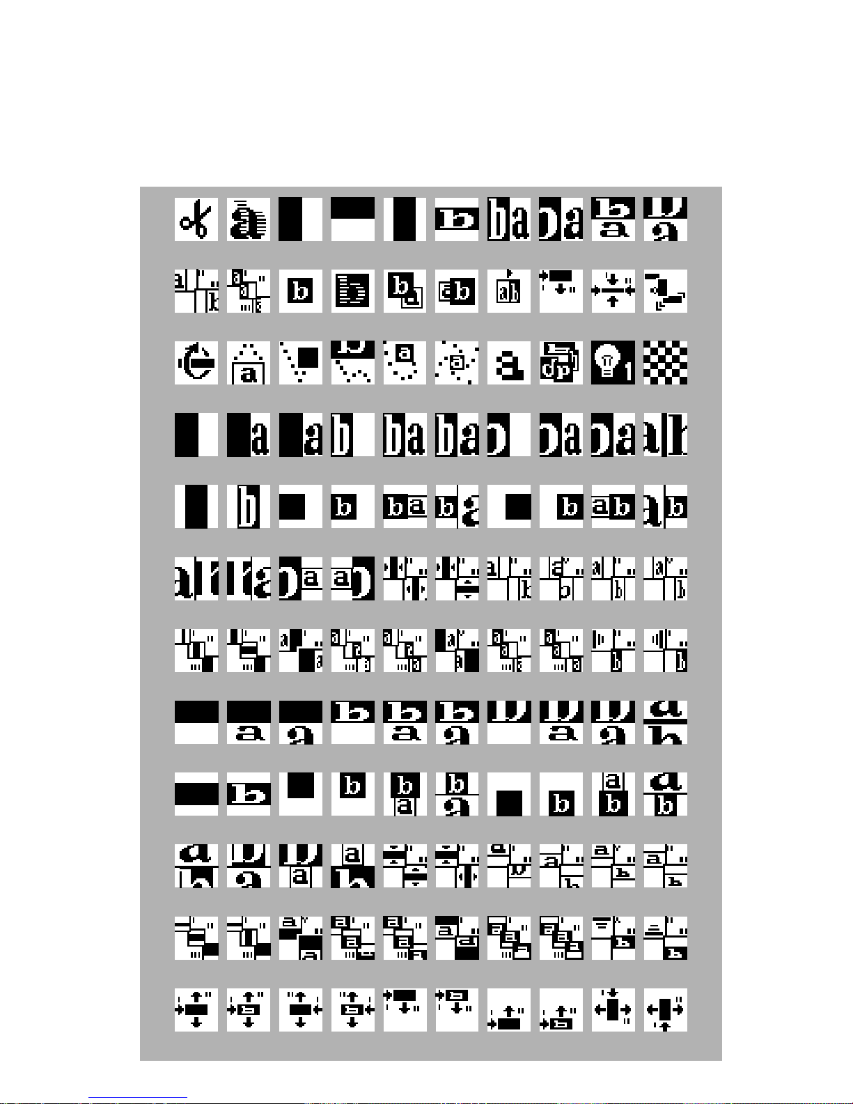
Reading the Transition Symbols: On-screen symbols
generally show the effect in the middle of the transition. The
symbol shows the effect in its forward direction (that is, not reversed). The dark area shows the incoming video (B) and the white
area shows the outgoing source. Letters “a” and “b” are used
0123456789
10 11 12 13 14 15 16 17 18 19
20 21 22 23 24 25 26 27 28 29
30 31 32 33 34 35 36 37 38 39
40 41 42 43 44 45 46 47 48 49
50 51 52 53 54 55 56 57 58 59
60 61 62 63 64 65 66 67 68 69
70 71 72 73 74 75 76 77 78 79
80 81 82 83 84 85 86 87 88 89
90 91 92 93 94 95 96 97 98 99
100 101 102 103 104 105 106 107 108 109
110 111 112 113 114 115 116 117 118 119
Page 93
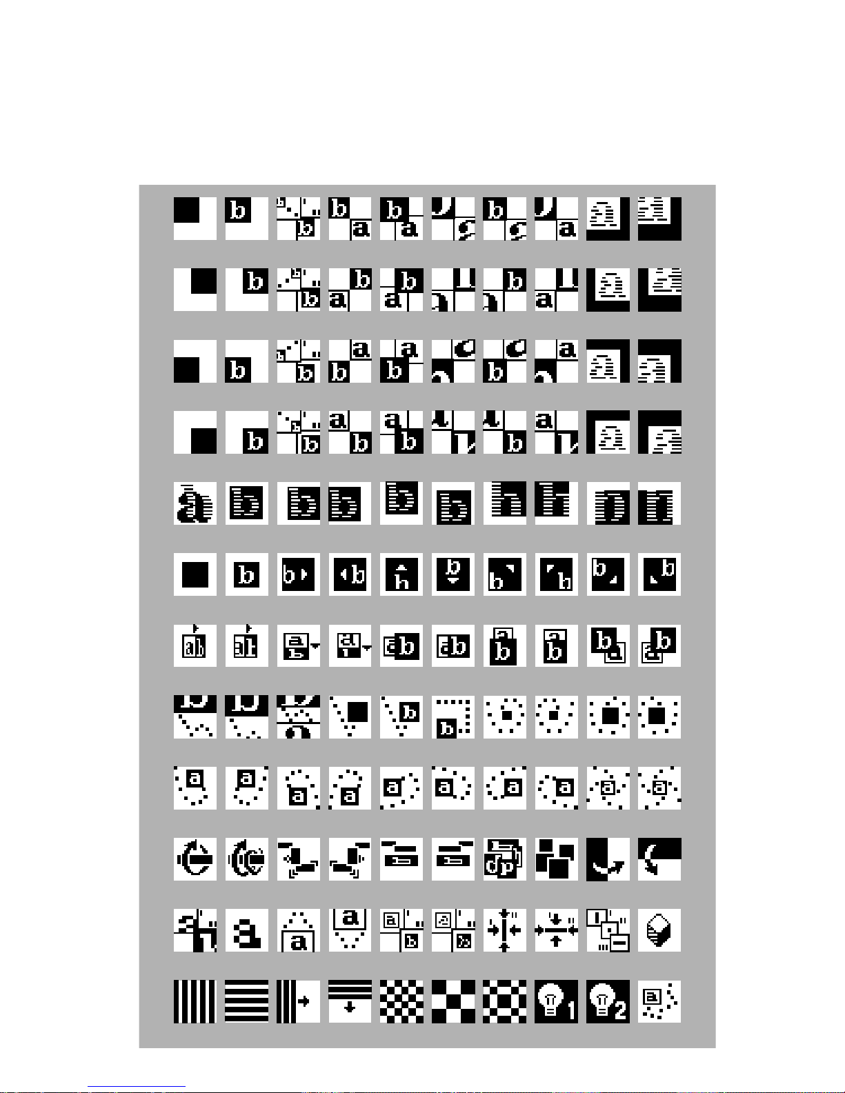
where needed to show action. For example, a squashed or shrunk
letter shows that the video is compressed; part of a letter sliding off
the screen indicates a slide; a flipped letter indicates a flip effect.
Multi-step effects are often indicated by I, II, and III. I indicates the
first step, II the second, and III the third.
120 121 122 123 124 125 126 127 128 129
130 131 132 133 134 135 136 137 138 139
140 141 142 143 144 145 146 147 148 149
150 151 152 153 154 155 156 157 158 159
160 161 162 163 164 165 166 167 168 169
170 171 172 173 174 175 176 177 178 179
180 181 182 183 184 185 186 187 188 189
190 191 192 193 194 195 196 197 198 199
200 201 202 203 204 205 206 207 208 209
210 211 212 213 214 215 216 217 218 219
220 221 222 223 224 225 226 227 228 229
230 231 232 233 234 235 236 237 238 239
 Loading...