

Page 1

AB-1 Edit Suite User Guide
Contents
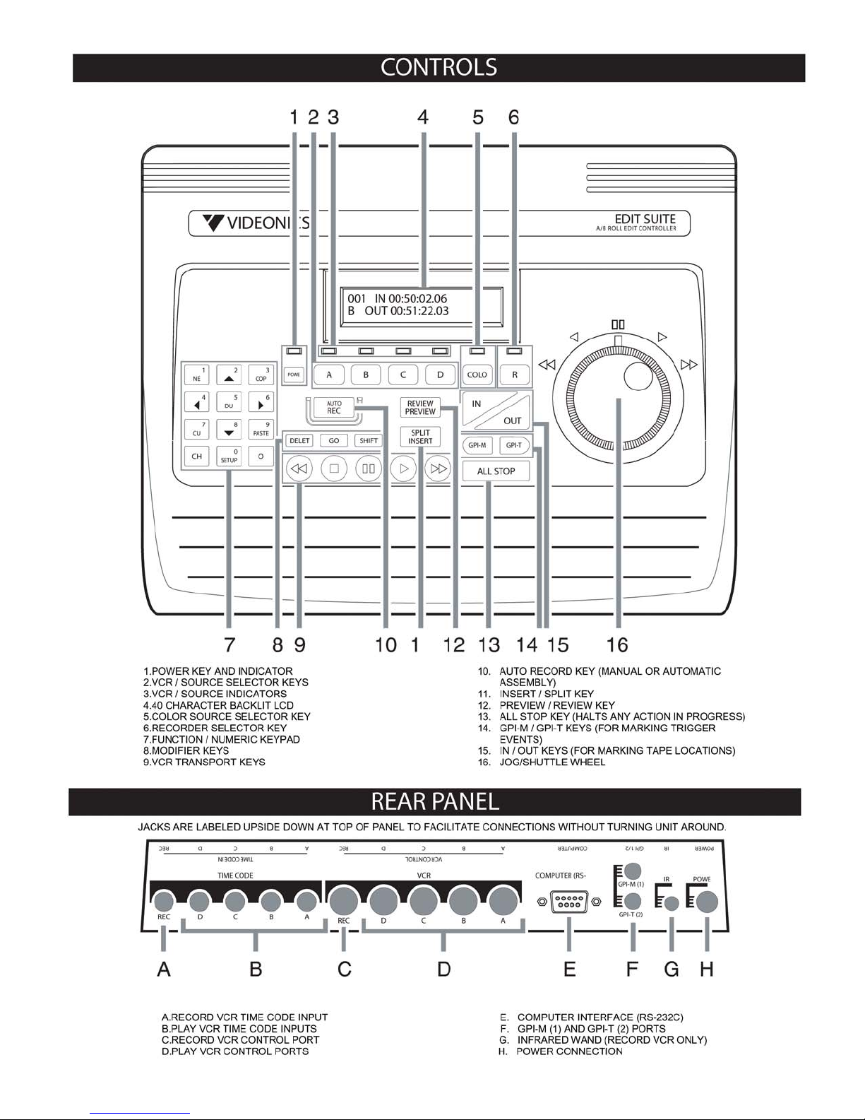
Controls and Back Panel
Chapter 1 • Introduction
• Overview of Edit Suite
• A Few Words About Time Code
• The Edit Decision List
Chapter 2 • Overview of the Keyboard
Chapter 3 • Getting Started
Chapter 4 • Making a Production
• Assemble Editing
• Auto-Assemble Editing
Chapter 5 • The NEW Menu and Edit Suite Events
• New Menu
• Scene (A/B/C/D) Events
• Source (SRC) Events
• MX1 Events
• Mixer Events
• GPI Events
• Insert (INS) Events
• Split Insert (SPLT) Events
• Stop Events
Chapter 6 • Managing The Edit Decision List
Chapter 7 • Fine Tuning
Chapter 8 • Importing and Exporting
• Export
• Import
• CMX
Page 2

Chapter 9 • Setup and Configuration Menus
Chapter 10 • Error Messages and Troubleshooting
Appendix A • VCR Tables
• PANA (Panasonic Control-M) Protocol
• LANC (Control-L) Protocol
• RS-422 Protocol
• RS-232 Protocol
• VCR Infrared Code List
Appendix B • Cables and Cable Pinouts
Appendix C • Equipment Hookup
Appendix D • Edit Control Chart
Appendix E • Key Reference
Appendix F • Off-Line Logsheet
Index
2.01 Addendum
Page 3
Page 4

Chapter 1 • Introduction
Edit Suite is a full-featured video editor that can simultaneously control up to four play VCRs/
camcorders, a record VCR, a mixer and a titler.
Edit Suite supports all of the primary editing control protocols–Sony Control-L (LANC), Panasonic 5pin (Control M), RS-232 and RS-422–so you can work with a wide variety of VCRs and camcorders
from a consumer level up to the professional level simultaneously. Edit Suite even supports record
VCRs with Infrared control!
Edit Suite reads all of the major time codes–LTC, VITC and RCTC–so you can get time-code accuracy
with all of your productions. If your VCRs do not support time code, Edit Suite will use the Real Time
Counter as its source for timing information.
Whether you have one play VCR and one recorder or a full complement of VCRs, camcorders, mixers
and titlers, Edit Suite will adapt to meet your needs.
How to Proceed
The remaining pages in this chapter provide a brief overview of Edit Suite, starting with how Edit Suite
fits in with the rest of your equipment, and ending with an introduction to the Edit Decision List.
Chapter 2 introduces the Edit Suite keyboard. Skim through Chapter 2, spending just enough time to
recall the primary functions and locations of the keys.
Next, proceed with Chapter 3, Getting Started. In Chapter 3 you will configure Edit Suite for use with
your equipment, hook up and test your connections, then create, preview and record an A/A Roll. If you
have a mixer and two play sources, Chapter 3 will also walk you through an A/B Roll.
Chapter 4 introduces assemble and auto-assemble editing, Chapter 5 provides detailed information about
each type of event you can create with Edit Suite, and Chapter 6 shows you how to manage the Edit
Decision List.
Fine Tuning is covered in Chapter 7. Use the fine-tuning procedures to adjust the timing Edit Suite uses
during an auto-record. Chapter 8 describes Edit Suite's import and export capabilities. Chapter 9
describes the Setup and Configuration Menus, and Chapter 10 describes the error messages you may
encounter. It also provides troubleshooting procedures for typical problems.
For More Information…
Page 5
…send in your registration card so we can keep you informed of new developments and send you our
newsletter. Note that Videonics does not sell its mailing list. Your name and address will remain
confidential.
An Overview of Edit Suite
Edit Suite is compatible with a wide range of VCRs, camcorders and editing equipment, such as video
mixers and switchers, title generators, video processors and audio mixers.
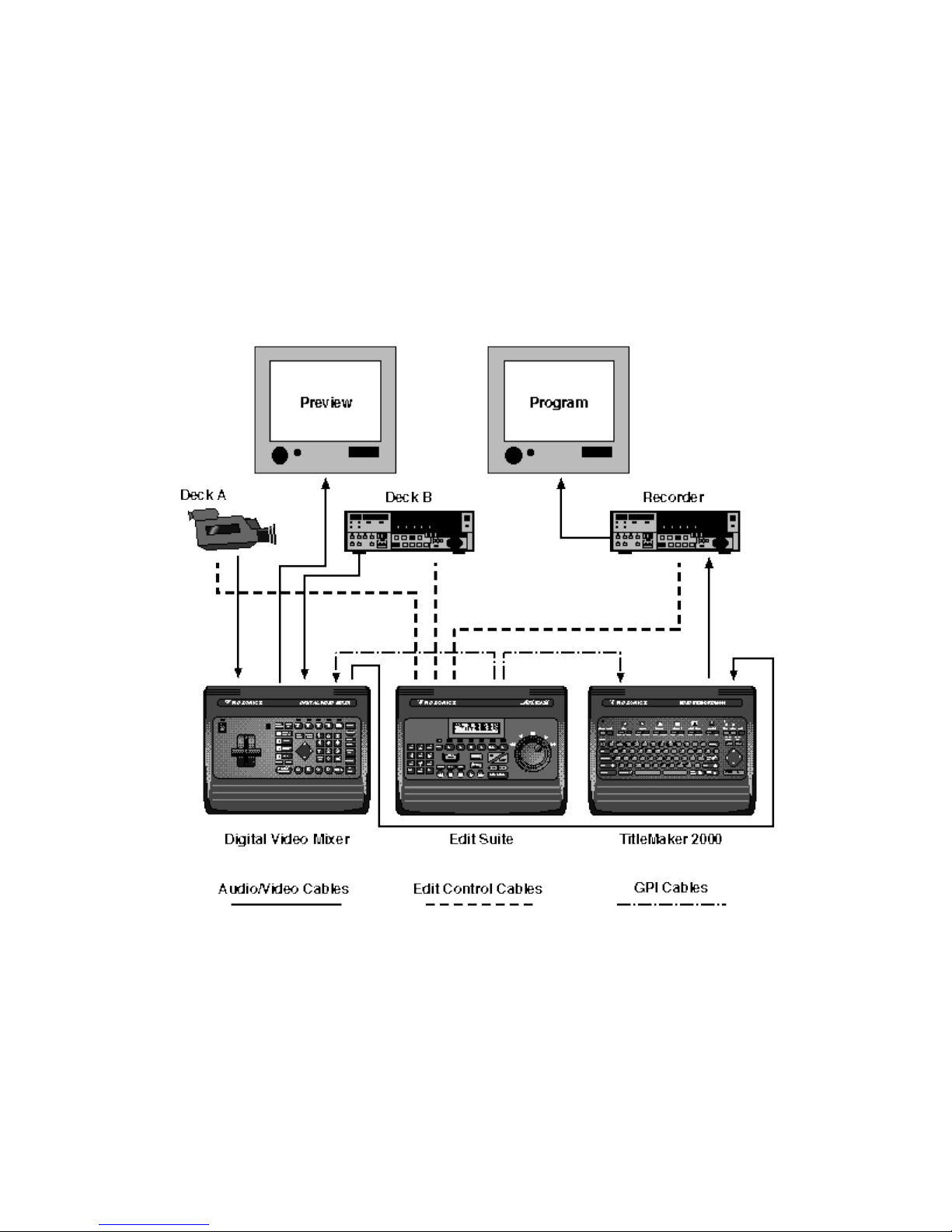
This figure shows a fairly typical configuration for Edit Suite. It includes two play sources (Deck A and
Deck B), a recorder, a Videonics MX-1 Mixer (left), a Videonics TitleMaker 2000 (right), and Edit Suite
in the middle to control the show. Up to two more play VCRs can be added to Edit Suite and the MX-1,
or you can even add noncontrollable sources like live cameraa or pattern generators to the MX-1 and
then just tell Edit Suite when you want to record video from those sources.
The Audio/Video Cables: No Video Passes Through Edit Suite
Page 6

Follow the path of the Audio/Video Cables. Audio and video signals are sent directly from each play
VCR/camcorder to the MX-1, from the MX-1 to the TitleMaker, and from the TitleMaker to the
Recorder. No video or audio passes through Edit Suite.
Edit Suite does not need to "see" the video–it just needs to know where the video is located. You provide
part of this information by locating and viewing the scenes you want to include in your production. Your
VCRs and camcorders provide the rest of the information by telling Edit Suite where on that videotape
the scenes start and stop. The start and stop locations are usually sent over the Edit Control Cables.
The Edit Control Cables
Trace the path of the Edit Control Cables. Each cable goes directly between Edit Suite and a VCR or
camcorder. The Edit Control cables are used by Edit Suite to send commands to the VCRs and
camcorders. The VCRs respond by changing operating modes, telling Edit Suite their current time code
or Real Time Counter position, and by telling Edit Suite what mode they are in (Stop, Play, Fast
Forward, etc.).
The GPI Cables
Trace the path of the GPI (general purpose interface) cables. One cable goes from Edit Suite to the MX-
1. A second goes from Edit Suite to the TitleMaker. For most devices except the MX-1, Edit Suite sends
a GPI trigger down the cable which causes a titler to play a screen of titles or a mixer/switcher to cut or
transition from one VCR to another.
With a Videonics MX-1, in addition to triggering the transitions, Edit Suite also sends all the setup
information the MX-1 needs to run the transition. It selects the MX-1's Current and Next sources
automatically, it tells the MX-1 which transition to use and at what speed and direction that transition
should be played, and it sets the color choices for the background and border.
A Few Words About Time Code
Time code is a digital code that is recorded on and identifies each frame of a video. When displayed,
time code is in an hours:minutes:seconds.frames format (hh:mm:ss.ff). Because the time code is a part of
the videotape, Edit Suite can search for a specific time-code value, and the video associated with that
value will be the same every time.
Without time code, Edit Suite must rely on the Real Time Counter in your VCR or camcorder to locate
your scenes. Because there is not a fixed relationship between the counter and the tape position, the
video that displays at a specific counter position may be slightly different each time you search to that
position. With proper care and setup, you can still create accurate productions, but they will not be quite
as accurate as when time code is used. Appendix D has a more detailed discussion of time code and edit
Page 7

accuracy.
A Few More Words About Time Code
Some VCRs and camcorders provide the ability to both read and write time code, and many of these can
send the time code over the Edit Control Cable. For example, RCTC (rewriteable consumer time code),
or a variant of RCTC, is available on many LANC and RS-232 VCRs. RCTC is always sent over the
Edit Control Cable.
LTC (Longitudinal Time Code) is written in an audio track on the videotape. With most RS-422 and RS232 VCRs that support LTC, the time code is sent through the Edit Control Cable. If you play the tape in
a VCR that uses LANC or PANA protocol, the LTC will not be sent through the Edit Cable. Instead, it
must be sent from the VCR/camcorder through an audio cable that you connect to the Time Code IN
port on Edit Suite.
The third major time code–VITC (vertical interval time code)–is written in the video signal a little bit
above the video that normally displays on your monitor. As with LTC, if VITC is played on a VCR that
uses LANC or PANA protocol, it must be sent over a cable attached to Edit Suite's Time Code IN ports.
Since VITC is recorded in the video portion of the tape, you must attach a cable from your VCR's video
OUT port.
The Edit Decision List
When you play your videotapes and see the video you want to record, you create a Scene Event to tell
Edit Suite which VCR contains the footage you are viewing, where that scene starts, and where that
scene ends. You just push a few buttons–Edit Suite fills in the information for you. (Or you can type in
the time codes manually.)
Each time you locate a scene you want in your production, you create a new Scene Event. Edit Suite
stores the events in a list called the Edit Decision List, or EDL. You can store up to 250 events in the
EDL at one time.
Page 8
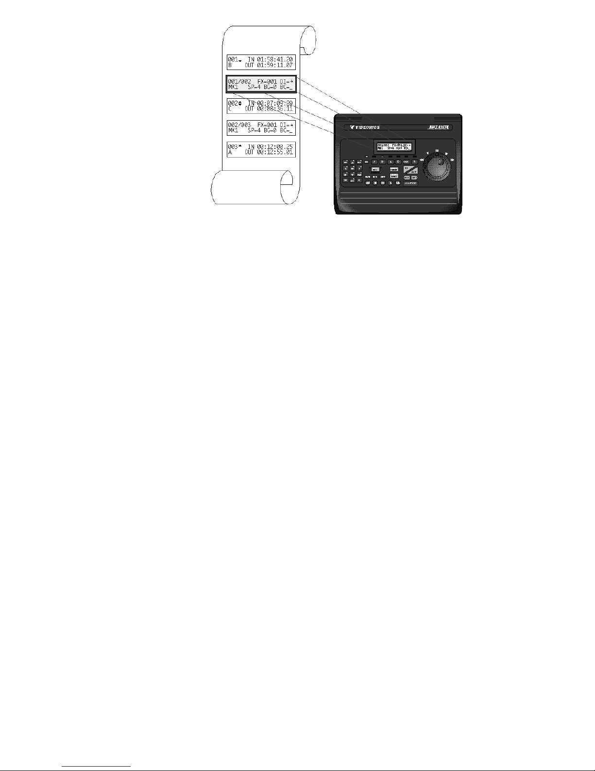
After you have created a few Scene Events, you can tell Edit Suite to preview or record the events. It
will march down the Edit Decision List finding each of your scenes, controlling your recorder and play
VCRs, and creating your production.
Now leaf through Chapter 2 and follow the instructions in Chapter 3 so you can begin putting Edit Suite
to work.
Page 9
Chapter 2 • Overview of the Keyboard
This chapter provides an overview of Edit Suite's LCD and keyboard. Take a few minutes to familiarize
yourself with the keyboard before proceeding with Getting Started. After completing the Getting Started
chapter, review this chapter again for reinforcement.
LCD
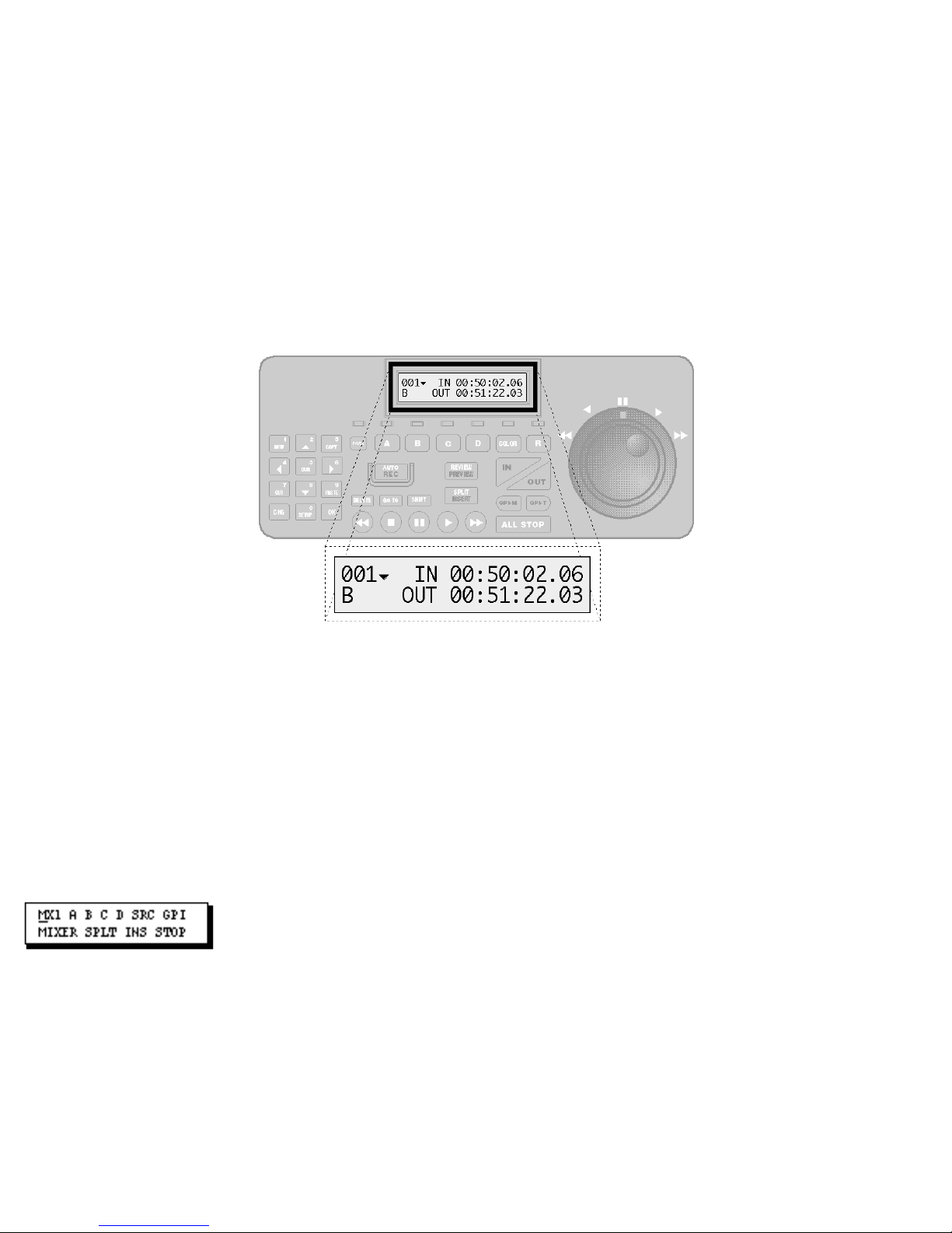
The LCD (Liquid Crystal Display) is located in the upper middle of the top panel.
The information in the display changes when function keys are pressed, scenes are created, or VCRs are
controlled. For example, the display above shows a Scene Event. Scene Events specify which VCR or
camcorder contains the video for a scene (VCR "B" in this case), and the starting (IN) and ending (OUT)
locations for the scene. The locations are shown in time-code format–hours:minutes:seconds.frames.
Another screen that is displayed often is the New Menu (below).
This menu provides one method of creating each type of event used with Edit Suite. To display the
menu, press the NEW function key.
Function/Numeric Keypad
Page 10
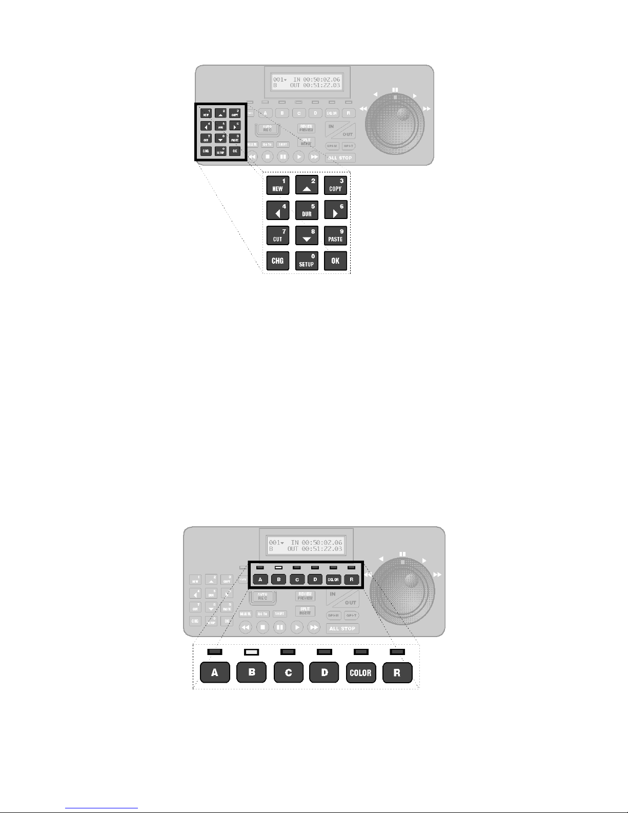
Located at the left side of the top panel are the twelve Function/Numeric keys.
The function keys are used to add new events to a production, to cut, copy, and paste events that were
created previously, and to display or change the duration of scenes. The arrow keys (keys 2, 4, 6 and 8)
are used to move up, down, left, and right between fields and screens of information.
The change key [CHG] key temporarily switches the keypad to numeric-entry mode, the OK key
confirms entries and clears messages, and the SETUP key accesses the Setup and Configuration menus.
Always press [CHG] prior to entering data.
VCR/Source Selector Keys and LEDs
Located just below the LCD are six VCR/Source Selector keys and their associated LEDs (light emitting
diodes).
• Five of the six keys–A, B, C, D and R–are used to select the VCR to control. When a VCR is
Page 11
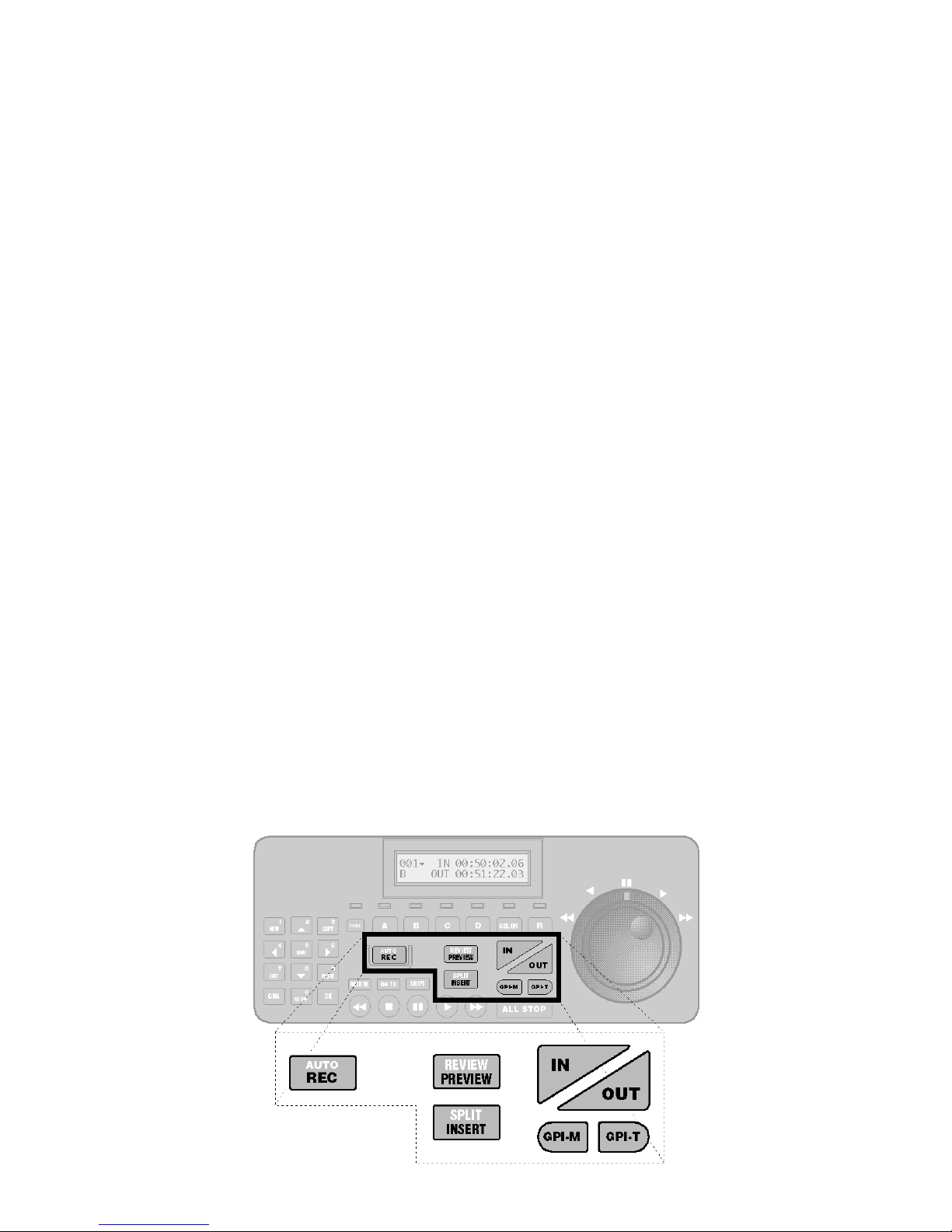
selected, the LED above the selector key lights, indicating that you have control of that VCR.
If a Videonics MX-1 is attached to Edit Suite, pressing the A, B, C, or D key also changes the
MX-1's output to the corresponding VCR.
• The sixth key–COLOR–is available to MX-1 users only, and is used to select COLOR as the
MX-1's current source. This is often used to do fades to and from black.
The LEDs above the selector keys indicate which VCR Edit Suite will control when a transport key is
pressed or the jog/shuttle is turned. There are four states for the LEDs:
1. If only one LED is lit, that VCR will be controlled.
2. If two LEDs are lit–one steady and one blinking slowly–the VCR with the steady LED is the
current VCR and it will be controlled. The VCR with the blinking LED is the next source. If a
mixer or switcher is attached, the next source is the "B" source in an A/B Roll.
3. If two LEDs are lit and one is flashing rapidly, that VCR is the "B" source in an A/B roll, and
it will be controlled. (There is a key sequence you will learn later to make the next source
controllable.)
4. If the "R" LED is lit, the record VCR will be controlled.
Production Keys
Located in the center portion of the top panel are the seven main production keys.
Page 12
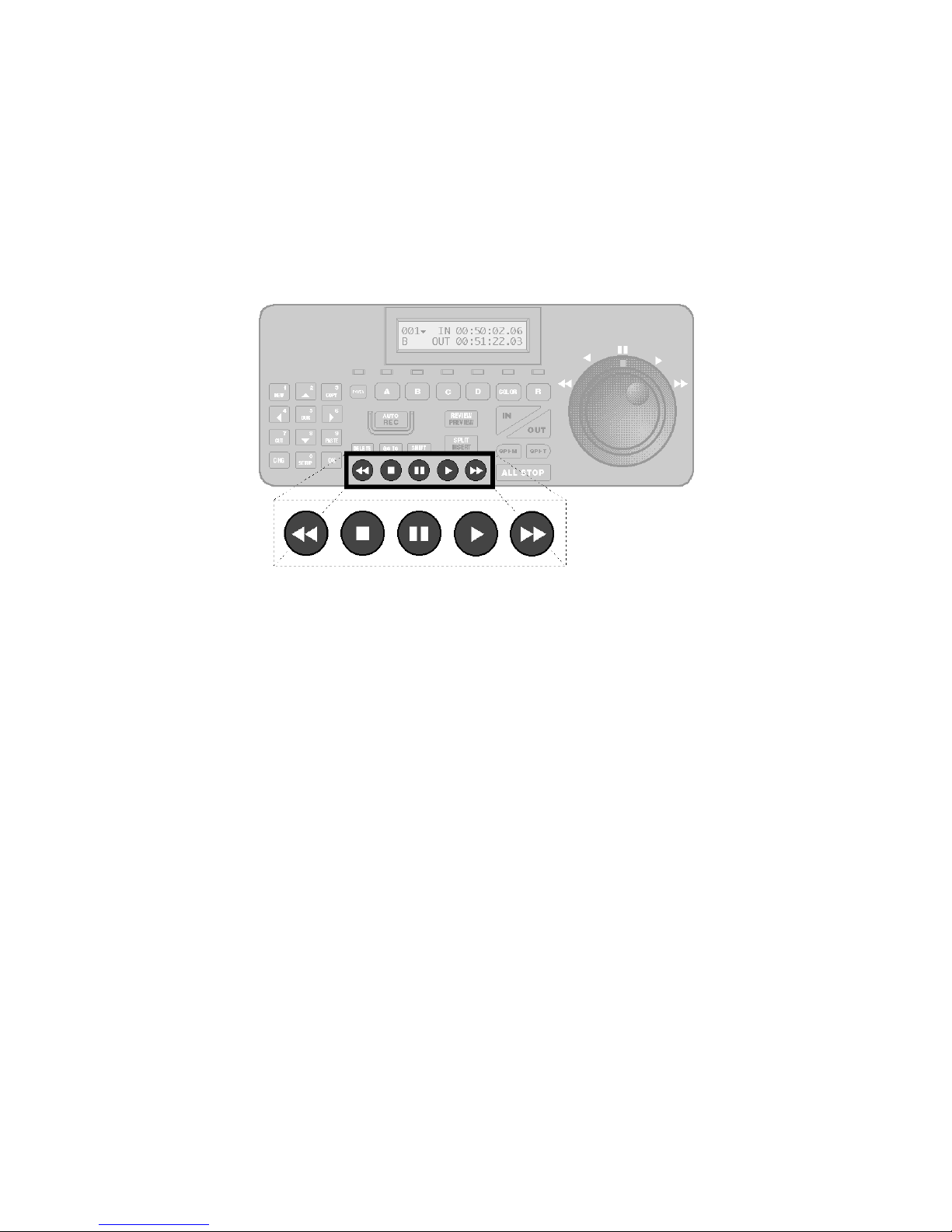
These keys are used primarily to create events, mark IN and OUT times for scenes, trigger mixers (GPI-
M) and titlers (GPI-T), create Insert and Split Insert Events, and start an auto-record, preview or review
of your production.
Transport Keys
Located at the bottom of the keypad are five Transport keys. They are, from left to right, Rewind, Stop,
Pause, Play and Fast Forward.
The Transport keys (and the jog/shuttle) are used to control the currently selected VCR (except Record
VCRs using Infrared control).
Jog/Shuttle
The jog/shuttle is used to locate and mark the scenes you want to record. It can control all of your VCRs
(except record VCRs using Infrared control), and it can be used for both rough and fine positioning.
The amount of control you get from the jog/shuttle depends on the capabilities of the VCR. If the VCR
does not have any speeds between pause and play, then you will not be able to get them with the jog/
shuttle. If, however, the VCR supports both frame-by-frame control and speeds as slow as 1/30th x Play,
the jog/shuttle will provide this same level of control.
Page 13
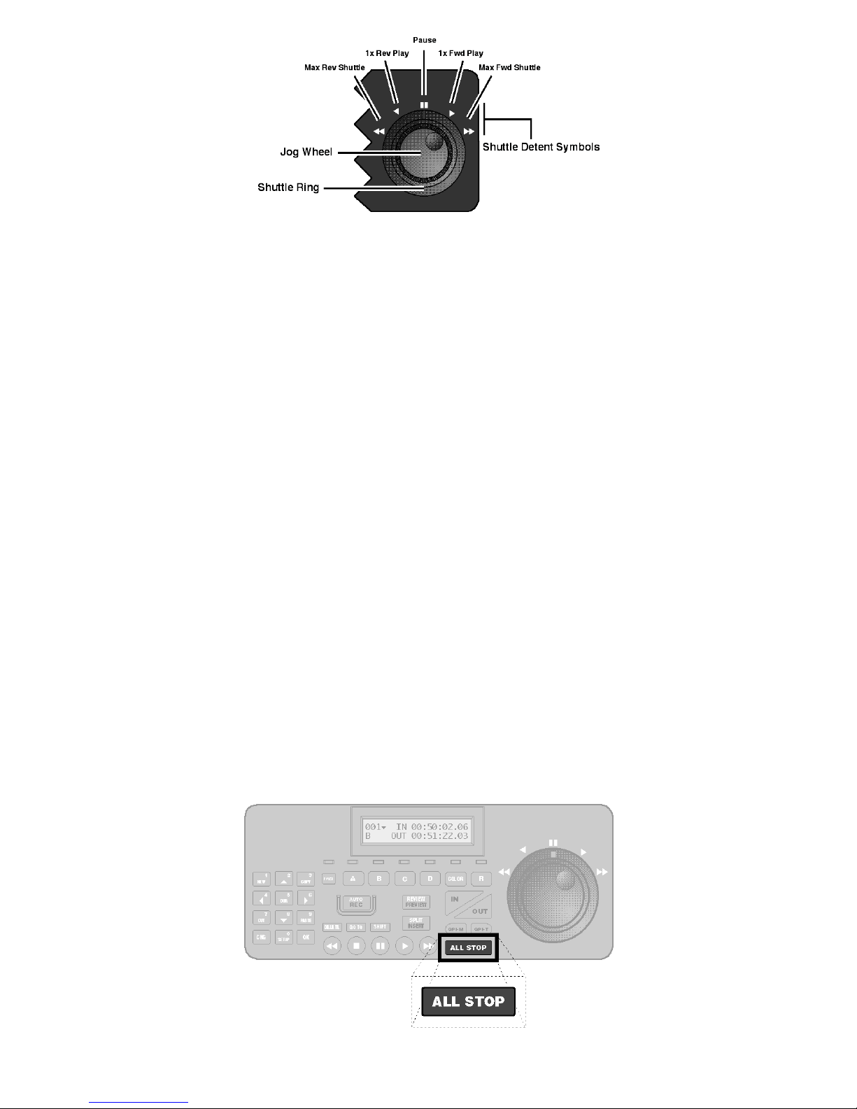
The Jog Wheel
For VCRs that allow frame-by-frame control, the jog wheel can advance or reverse the video one frame
at a time. Depending on the VCR table you select (Appendix A), turning the jog forward at a slow speed
will advance the video from three to seven frames per revolution. Turning the jog faster will advance the
video at speeds ranging from ±1/30th x Play to standard play speed.
Note: The jog can be used only when the shuttle is in the Pause position.
A secondary function of the jog/shuttle is to trim numeric values. As a general rule, anywhere you can
make a numeric entry in Edit Suite, you can use the jog/shuttle to change that entry.
The Shuttle Ring
Again, depending on the capabilities of the VCR, the shuttle provides for forward and reverse control at
speeds ranging from ±1/30th x Play to speeds greater than ±20 x Play. When the shuttle is turned you
will feel detents at five locations. The center detent is Pause; the middle detents are Play and Reverse
Play, and the outer detents are maximum forward and reverse shuttle.
ALL STOP
Located directly to the right of the Transport Control keys is the ALL STOP key.
Page 14
ALL STOP is used to stop the motion of all connected VCRs and camcorders. If an auto-record,
preview, or review is in progress, it is terminated. Depending on the VCR, when ALL STOP is pressed
the VCR will be placed either in STOP or in PAUSE.
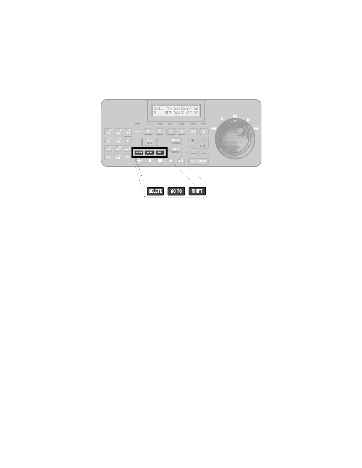
Modifier Keys
Located below the AUTO REC key are three function modifier keys.
The Modifier Keys–Delete, Go To, and Shift–are used in combination with the Function, Selector,
Production and Transport keys to access many of Edit Suite's functions. In all cases where two or three
keys are required to access a function, the first one or two keys will be modifier keys.
When you see a reference to two or three keys, such as–
[SHIFT]+[UP ARROW] or
[GO TO]+[SHIFT]+[UP ARROW]
all keys must be pressed to start the function.
Modifier keys must be pressed and held down first, followed by the function key. In the first example
above, press and hold the [SHIFT] key, then press the [UP ARROW] key. In the second example, press
and hold both the [GO TO] and the [SHIFT] keys, then press the [UP ARROW] key.
Page 15
Getting Started
This chapter provides the information required to add Edit Suite to your existing
setup, configure Edit Suite to work with your VCRs, and to create, preview and
record a single-source and an A/B Roll production.
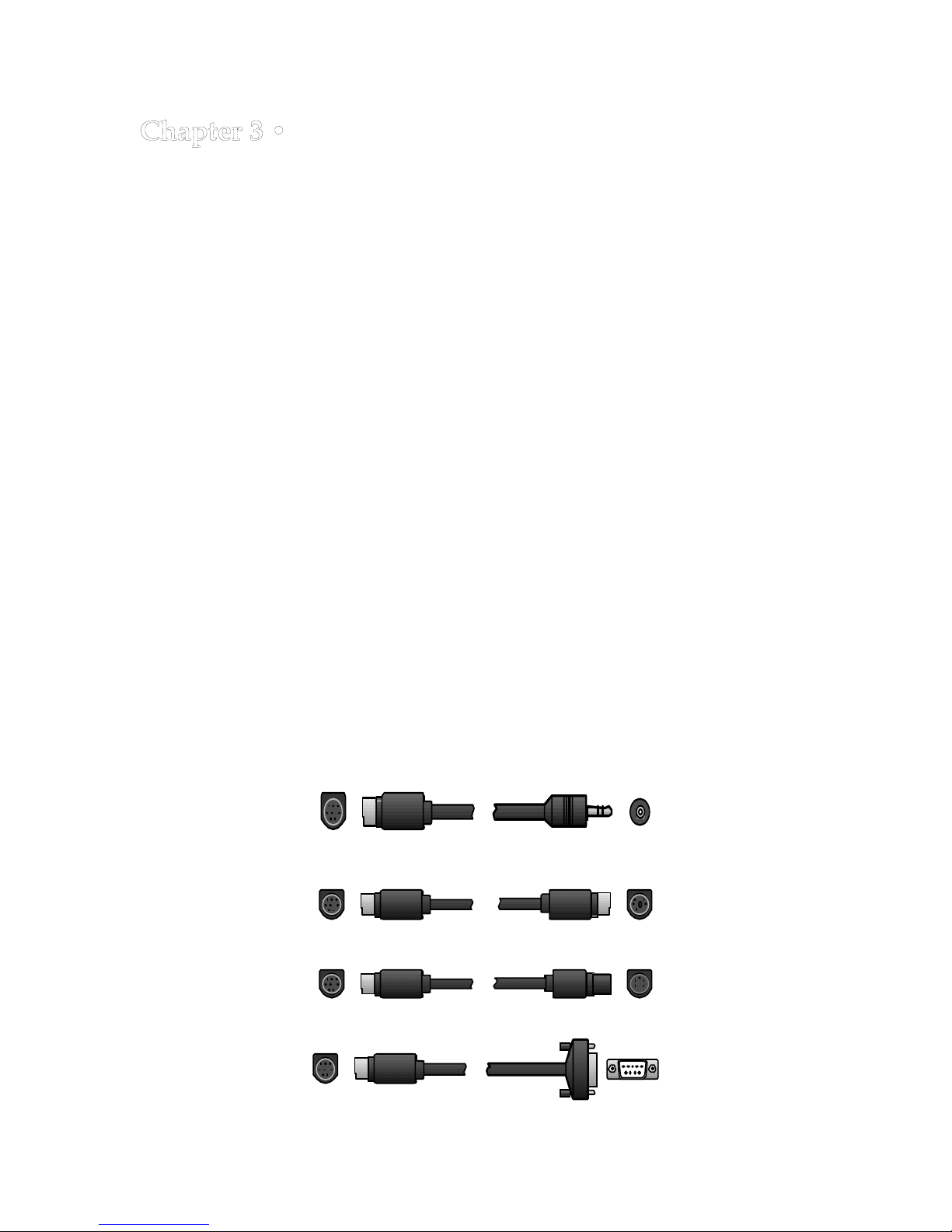
1. Check for Correct Edit Control Cables and GPI Cables
• Determine the type of Edit Control cable needed for each of your VCRs
and camcorders—but do not attach the cables to Edit Suite yet. Your
VCR/camcorder manuals and the figures below should help you
determine which cables you need. (Note the difference in pin positions
between the Control-L 5-pin and the Panasonic 5-pin. These cables are not
interchangeable.)
Edit Suite comes with three Control-L submini cables, three Panasonic 5-
pin cables and one IR (infrared) wand. If you need different or additional
cables, follow the instructions on the Cable Exchange Card or contact the
distributor in your conutry.
For customers with RS-232 or RS-422 VCRs who wish to make their own
cables, a cable pin-out chart is provided in Appendix B. Most RS-232 users
will also need a 9-pin to 25-pin adapter and, for most RS-232 VCRs [except
Panasonic], a null modem. These are available at any computer parts
store.
• A stereo GPI (general-purpose interface) cable is provided to connect Edit
Suite to your mixer or titler. If you have both a mixer and a titler, you will
need a second GPI cable. This is a standard stereo mini-jack to stereo minijack cable available from most audio or computer parts stores, from your
Videonics dealer, or direct from Videonics.
Edit Suite to Sony LANC (Control-L Submini)
Edit Suite to Sony LANC (Control-L 5-pin)
Edit Suite to Panasonic 5-pin (Control-M)
Page 16
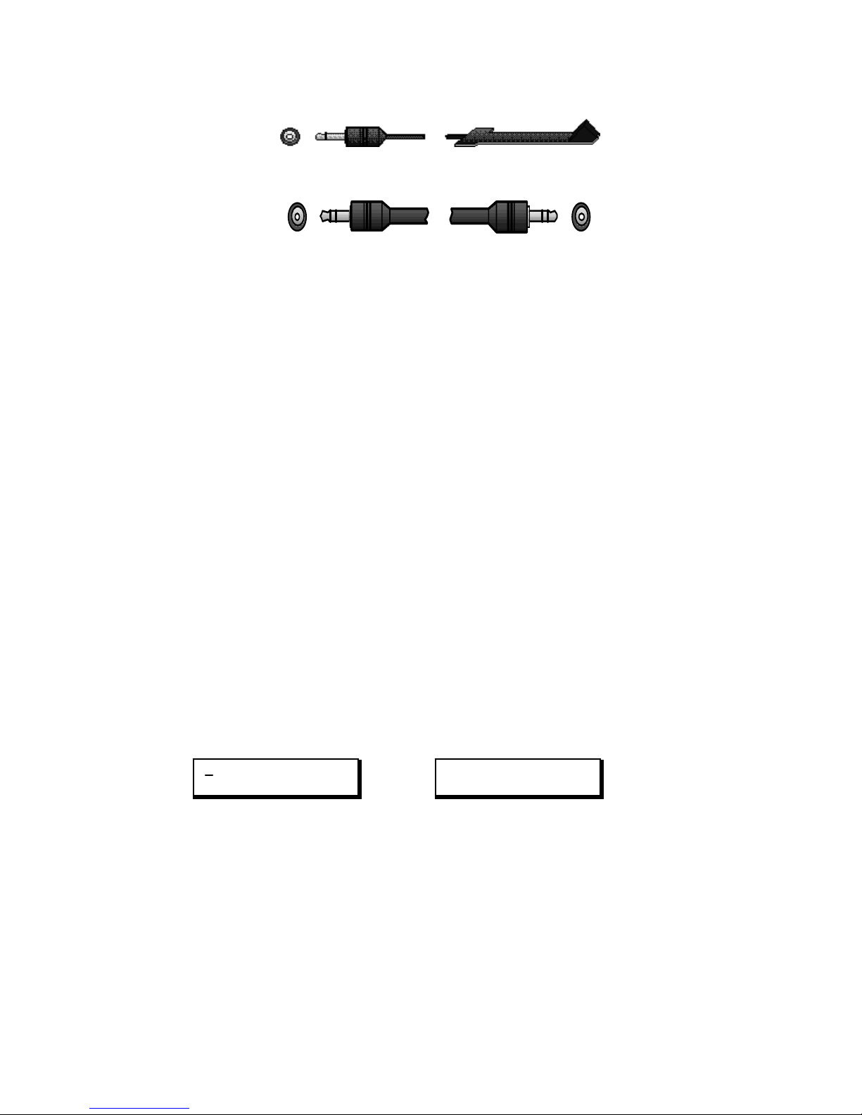
Edit Suite to RS-232/422 (DB-9)
Edit Suite IR to Infrared Wand (mounted near VCR's IR window)
Edit Suite GPI-M/GPI-T to Mixer/Switcher/Titler GPI
2. Set Up and Test VCRs/Mixer/Titler Without Edit Suite
• Edit Suite will be an add-in to your existing video editing setup, so if you
have a mixer or switcher, set up your equipment (VCRs, camcorders,
titlers and monitors) as described in your mixer/switcher manual.
• If you do not have a mixer, connect the audio and video outputs from
your play VCR/camcorder to the corresponding inputs on your record
VCR (via a titler, if applicable). Connect the audio and video outputs from
the record VCR to the inputs on your monitor. Make sure both the
monitor and the VCR are set to receive audio and video inputs.
• Verify that your sources display, play and record as expected. If you have
any problems, refer to Appendix C, Equipment Hookup.
3. Connect Power to Edit Suite
• Connect the Edit Suite power supply to the POWER input jack (back panel
of Edit Suite) and plug the power supply into a working power outlet.
Edit Suite will turn on, run through its startup routine, and then display
either the New Menu or the Demo messages (shown below).
The Demo is a scrolling list of Edit Suite's features. The list will play over
and over again, so move to Step 4 whenever you are ready.
MX1 A B C D SRC GPI
MIXER SPLT INS STOP
New Menu Demo: Scrolling Feature List
Note: If you have used Edit Suite previously and created any events, either the
Demo or the first event in your list will display.
Videonics . . .
Edit Suite
Page 17
4. Display the Configuration Menu
Before Edit Suite can control your VCRs, it needs to know the type of VCR
that will be attached to each VCR Control Port, the type of time code (RCTC,
VITC, LTC)—if any—that will be used, and other information that customizes
the way Edit Suite communicates with each VCR. You specify this
information by selecting a VCR port to configure and then entering values in
configuration parameters.
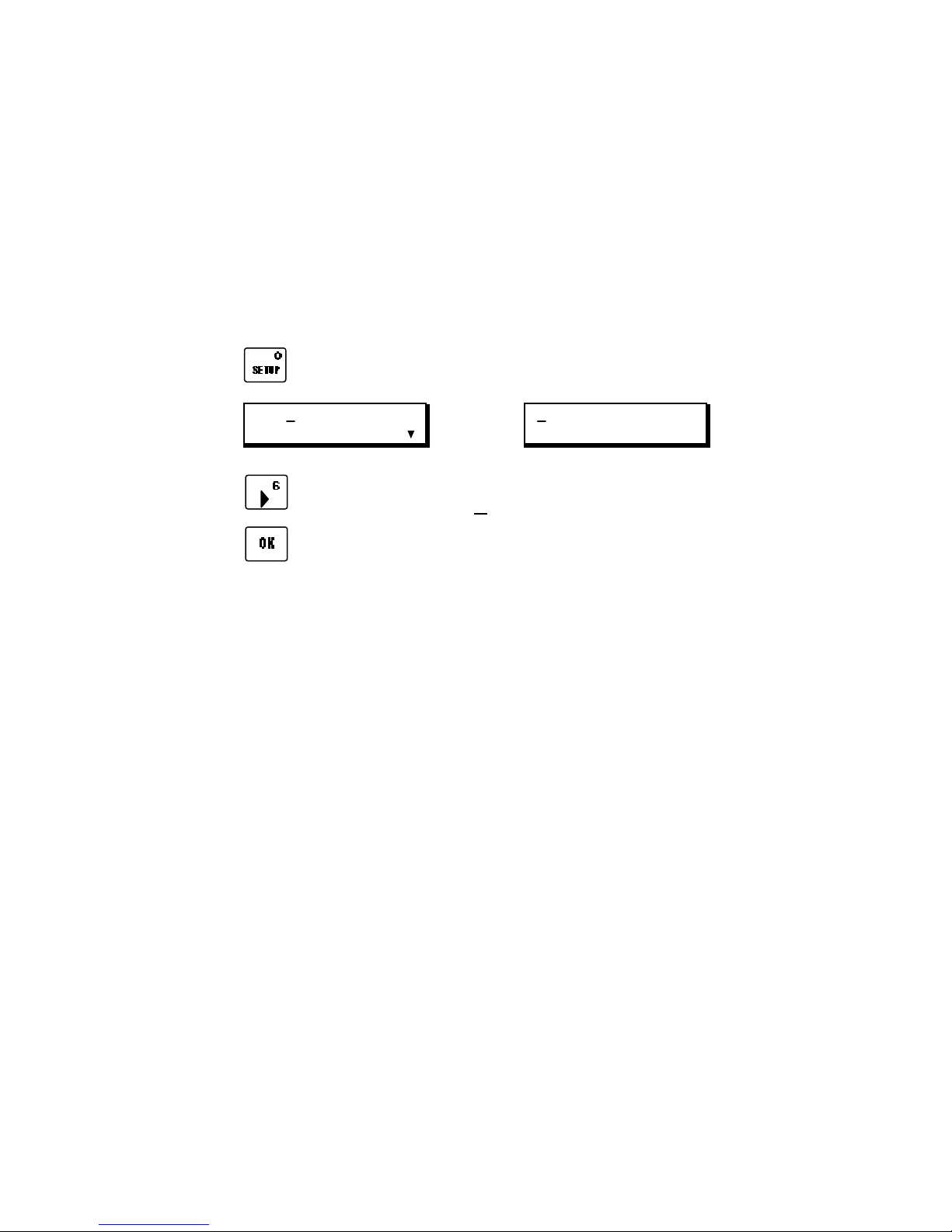
Start by displaying the Configuration Menu—
A. Press
Setup Menu 1 Configuration Menu
B. Press
C. Press
to display Setup Menu 1.
LCD CONFIG NEWVCR
IMPORT EXPORT CMX
to move the cursor to CONFIG.
to display the Configuration Menu.
VCRA VCRB VCRC VCRD
VCRR GPI-M GPI-T
The Configuration Menu is used to select the VCR or GPI ports to
configure and to display the parameters for that port. VCRA is used to
configure Edit Suite's VCR Control Port A, VCRB configures VCR Control
Port B, and so on. VCRR configures the Record VCR, GPI-M configures
the GPI-M port, and GPI-T configures the GPI-T port.
Page 18
5. Select and Configure the VCR Ports
• If you have a mixer or switcher, Edit Suite's VCRA port must match the
mixer's input A or input 1; VCRB must match the mixer's input B or input
2, and so on. VCRR is for the record VCR.
• If you are not using a mixer/switcher, configure VCRR for your record
VCR and any of the other ports for your source VCR(s).
To configure the ports—
A. Press
and
to move the cursor to the VCR port you want to
configure, then—
press
to display the first screen of Configuration Parameters for that
port.
VCRA VCRB VCRC VCRD
Configuration Menu Configuration Parameters
VCRR GPI-M GPI-T
PROTO=NONE
VCR=001 PREROLL=05
Page 19
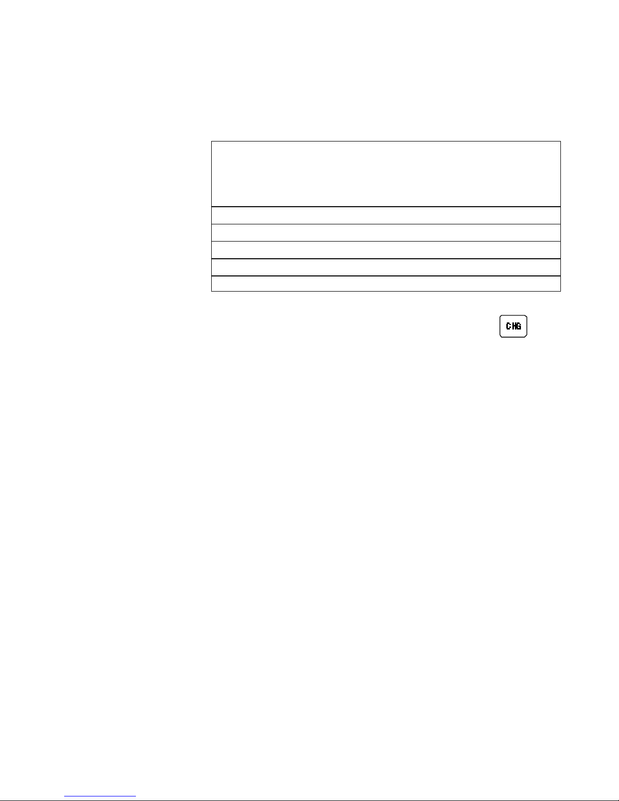
B.Use the information below to determine and set the values for the PROTO,
VCR, TCSRC and TC parameters.
PROTO Type of control protocol. Your choice here should match
the type of cable you identified in Step 1. The choices are:
NONE Either this port is not used, or a noncontrollable source—
such as a live camera—is connected to the corresponding
port on your mixer/switcher. In either case, no cable is
attached to this Edit Suite control port and no other
parameters need to be specified for this port.
IR Infrared is used (record VCR only [VCRR]).
LANC Sony LANC (Control-L) protocol is used.
PANA Panasonic 5-pin (Control-M) protocol is used.
232 RS-232 protocol is used.
422 RS-422 protocol is used.
To select a protocol, with the cursor in the PROTO field
press
repeatedly to cycle through the list of choices. Stop when
the value you want is displayed.
If RS-232 protocol is selected, choices for baud rate and character
format display. Check the manuals for your VCR to
determine these values. To change values, press the
left/right arrow keys to move the cursor to the field, then
press [CHG] repeatedly until the correct choice is
displayed.
NOTE: If your record VCR uses IR, after configuring all of your play
VCRs, skip to Step 6.
Page 20
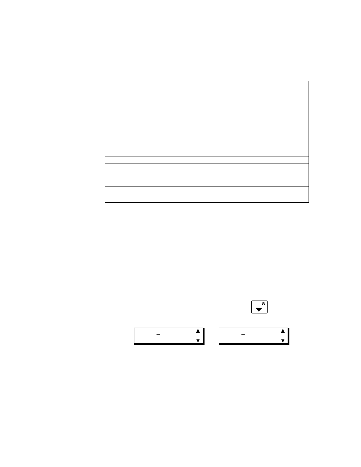
VCR VCR Table Number. The table below lists several of the
VCR numbers available with Edit Suite. Start with a value
from this table. Additional VCR numbers and detailed
descriptions are listed in Appendix A.
PROTO VCR #
LANC 001 for VCRs (121 if RCTC is used*)
002 for Camcorders (122 if RCTC is used*)
007 for CCD-V5000 (124 if RCTC is used*)
012 for Canon (125 if RCTC is used*)
* if RCTC is used, the time code may not be passed to Edit
Suite during Rewind or Fast Forward. If your VCR/
camcorder counter goes blank or skips values during
Rewind or Fast Forward, use these table numbers.
PANA 001 for VCRs and Camcorders
232 001 for Sony; 005 for UVW-1400
003 for Panasonic
004 for JVC
422 001 for VCRs with 1/30th X Play shuttle speed
002 for VCRs with 1/10th X Play shuttle speed
IR Skip to Step 6.
To enter a VCR table number, use the left/right arrow keys to move
to the VCR field, then press [CHG] once. The cursor will
change to a blinking block and the numeric keys on the
keypad are activated. Type the three-digit value from the
table. After the last digit is entered, the blinking cursor
reverts to an underline and the keypad reverts to its nonnumeric functions. If you make a mistake, press [CHG]
again and reenter the number.
No change to the PREROLL value is needed at this time.
To display the next group of parameters, press
following will display.
TCSRC=INT TC=NONE
VCRA ... VCRD VCRR
TCSRC=INT TC=NONE
INS=0 SPLT=0
TCSRC Time Code Source. Specifies whether time code—if used—
is sent via the Edit Control Cable or via an audio or video
cable attached to Edit Suite's Time Code IN jack.
. One of the
Choices are INT (internal: sent through the edit control cable) and
EXT (external: sent through an audio or video cable). INT
should be used in all cases except when LTC or VITC time
Page 21

code will be delivered via a cable attached to a Time Code
IN jack. If time code is not used, select INT.
To change the TCSRC choice, use the arrow keys to move to the
TCSRC field and press [CHG].
TC Time Code Type. Specifies the type of time code—if any—
that will be used. The choices are NONE, RCTC, VITC and
LTC. If you are not sure if you have time code, select
NONE for now. You can change this choice later.
To change the TC choice, use the arrow keys to move to the TC field
and press [CHG] until the correct time-code type is
displayed.
The INS (insert) and SPLT (split insert) parameters (record VCR only) do
not need to be set now. However, if you know that your record
VCR supports insert editing, you can change the value for INS
to 1 now by pressing [CHG]. If it also supports split inserts,
change that value to 1, too. Your VCR Operating Manual
should indicate if your VCR has these capabilities.
Advanced Parameters
C. Verify that the advanced parameters for the port you are defining are
set to the values below. If not, change them to these values.
PLY Play Threshold (set to 00:15)
REW Rewind Threshold (set to 00:30)
FFD Fast Forward Threshold (set to 02:00)
STABLE Stable Period (set to 45)
These parameters determine how Edit Suite searches for scenes when
you preview or record your production.
To access the advanced parameters, press the down arrow enough
times to skip past the offset parameters and display the
ADVPARAMS screen, then press [OK].
To change the advanced parameters, use the arrow keys to move to
the desired field, press [CHG] once, then type in the new value.
If you make a mistake that you notice before you have finished
entering a value, press [CHG] twice: the first press erases your change
and cancels change mode; the second press reactivates change mode.
Remember, the cursor must be a flashing block before you can use the
number keys.
Page 22

If you inadvertently press SETUP before you are done, you are
returned to the ADVPARAMS screen. Press [OK] again to redisplay
the advanced parameters.
D. Press [SETUP] twice. Edit Suite will configure the VCR port you just
defined and return you to the Configuration Menu. While the port is
being configured, a wait indicator displays in the lower, right corner
of the display.
E. Repeat Step 5 for all other VCR ports you will be using.
Page 23
6. Configure and Test a Record VCR With IR Control
IR works for the record VCR only. If your record VCR uses IR Control,
complete this step. Otherwise, skip to Step 7.
In this step, you will determine what command takes your VCR to Record
from Record Pause (Pause, Play or Record), how to position the IR wand, and
how to find the correct VCR number to control your VCR.
A. If you have not already done so, select PROTO=IR by moving the cursor
to the PROTO field and pressing [CHG] until the IR choice is displayed.
The display will look similar to the one shown below.
PROTO=IR CMD=PAUSE
VCR=001 PREROLL=05
In later portions of this step you will need to enter values in two fields:
VCR and CMD. VCR is the Edit Suite table number that controls your
VCR. CMD is the command your VCR uses to move the deck from Record
Pause to Record.
B. Press [SETUP] to save your choice and return to the Configuration Menu.
C. Unplug the power supply from Edit Suite.
D. Plug the IR wand into the IR jack on the back panel of Edit Suite (next to
the POWER jack).
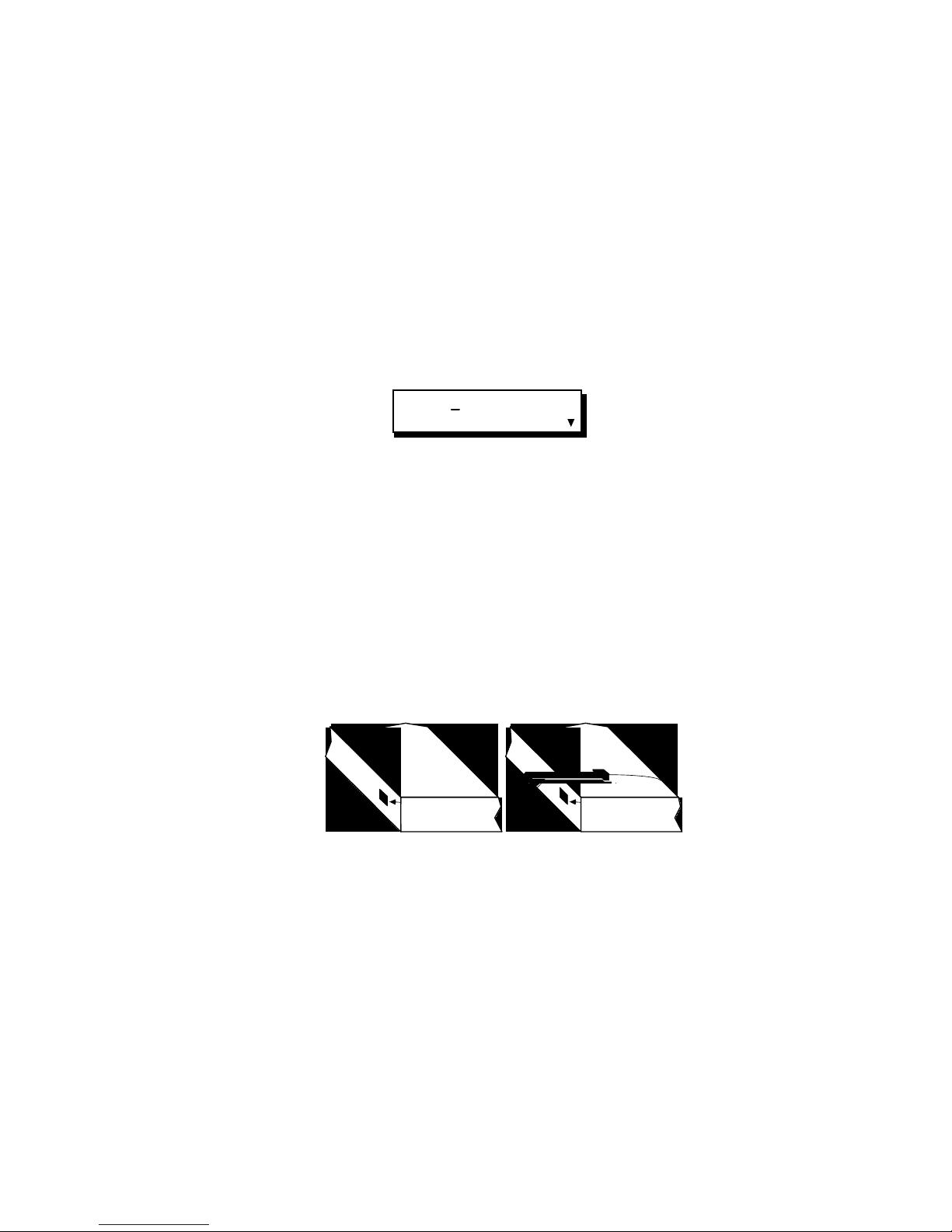
E. Position the IR Wand near the IR window on your record VCR.
IR Window IR Window
Record VCR
Record VCR
F. Determine which command your record VCR uses to change from Record
Pause to Record: Pause, Play or Record. (Pause is used by most VCRs.) To
do this, load a blank tape into your record VCR, put the VCR into Record
Pause, then press the Pause button on your VCR or remote control. If the
VCR goes into Record, then this is the command to use in the CMD field
in Edit Suite. If the VCR does not go into Record, try the Play and Record
commands. Stop the recorder after you determine the command to use.
G. Reconnect power to Edit Suite. After the demo begins or the NEW Menu
displays, reselect VCRR by—
- pressing [SETUP] to display the Setup Menu
Page 24
- moving the cursor to CONFIG and pressing [OK]
- moving the cursor to VCRR and pressing [OK].
H. Refer to the IR Table in Appendix A to determine the VCR table numbers
that work with your brand of VCR. If your brand of VCR is not listed in
the table or if you have already tried the VCR table numbers that are listed
for your brand, skip to Step M.
I. Use your VCR's control panel or remote control to put your record VCR
into Record.
J. Move to the VCR field, press [CHG] to activate the numeric keys, then
enter one of the three-digit VCR numbers from Step H.
PROTO=IR CMD=PAUSE
VCR=001 PREROLL=05
K. IMPORTANT: Do this step even if the CMD field is already set correctly.
Edit Suite needs to build the commands for you to test, and it will not do
this until the value in the CMD field is changed, you press [SETUP], or
you do the procedure in Step M.
Move to the CMD field and press [CHG] enough times to display the
command used to put your VCR into Record from Record Pause. (This is
the command you determined in Step F.)
L. Make sure the recorder is still in Record, then press Edit Suite's PAUSE—
—transport key. This will send a command to the VCR telling it to
change to Record Pause.
• If the VCR goes into Record Pause, then the table number is correct
and your VCRR configuration is complete. Move to Step 7.
• If the VCR does not go into Record Pause, repeat Steps J, K, and L for
the other VCR codes you determined in Step H.
• If you have tried all the codes you determined in Step H, continue with
Step M.
M. If none of the VCR codes listed in Appendix A worked for your VCR, use
the automatic IR test feature of Edit Suite.
• Change the VCR number to 001, set the CMD field to the correct
command value, and ensure your VCR is still in Record.
• Test Table 001 by pressing Edit Suite's PAUSE transport key. If the
VCR goes into Record Pause, table 001 is the correct table. Skip to Step
7.
Page 25
• Press Edit Suite's Fast Forward (>>) transport key. Edit Suite will build
table 002, automatically change the VCR field value to 002, then send
the Record Pause command to your VCR.
- If the VCR pauses, the table number is correct and you are done
with your IR setup.
- If the VCR does not pause, continue pressing Edit Suite's Fast
Forward transport key until you find a table that does work.
7. Configure the GPI-M Port
A. Return to the Configuration Menu, select GPI-M, and press [OK]. The
GPI-M configuration screen will display.
VCRA VCRB VCRC VCRD
VCRR GPI-M GPI-T
GPI-M = MX-1
Configuration Menu GPI-M Configuration Screen
B. Press [CHG] to cycle through the three choices. Select MX-1 if you will be
using a Videonics mixer, select MIXER if you will be using a third-party
mixer or switcher, or select GPI if you will not be using a mixer. The
MIXER and GPI choices have an associated offset value. Leave the offset
value set to +0000 for now.
C. Press [SETUP] twice to exit the Setup menus and return to the NEW
Menu. (No changes to the GPI-T port configuration are required.)
MX1 A B C D SRC GPI
MIXER SPLT INS STOP
New Menu
8. Attach Cables and Power-On Equipment
• For each VCR port you defined in Step 5 (except for Record VCR's using
IR Control), attach an edit control cable between the VCR/camcorder and
the appropriate VCR Control port on Edit Suite (A, B, C, D, REC).
• If you specified EXT (external) in the TCSRC field for a port, you will need
to attach an audio cable (LTC) or video cable (VITC) from your
VCR/camcorder to the corresponding Time Code IN port on Edit Suite.
This delivers the time code from your video tape to Edit Suite.
• If the record VCR uses infrared (IR) control and it is not already plugged
in, unplug the power supply from Edit Suite, plug the IR wand into the IR
jack, then reconnect the Power Supply. Position the wand near your
record VCR's IR sensor as shown in Step 6.
Page 26
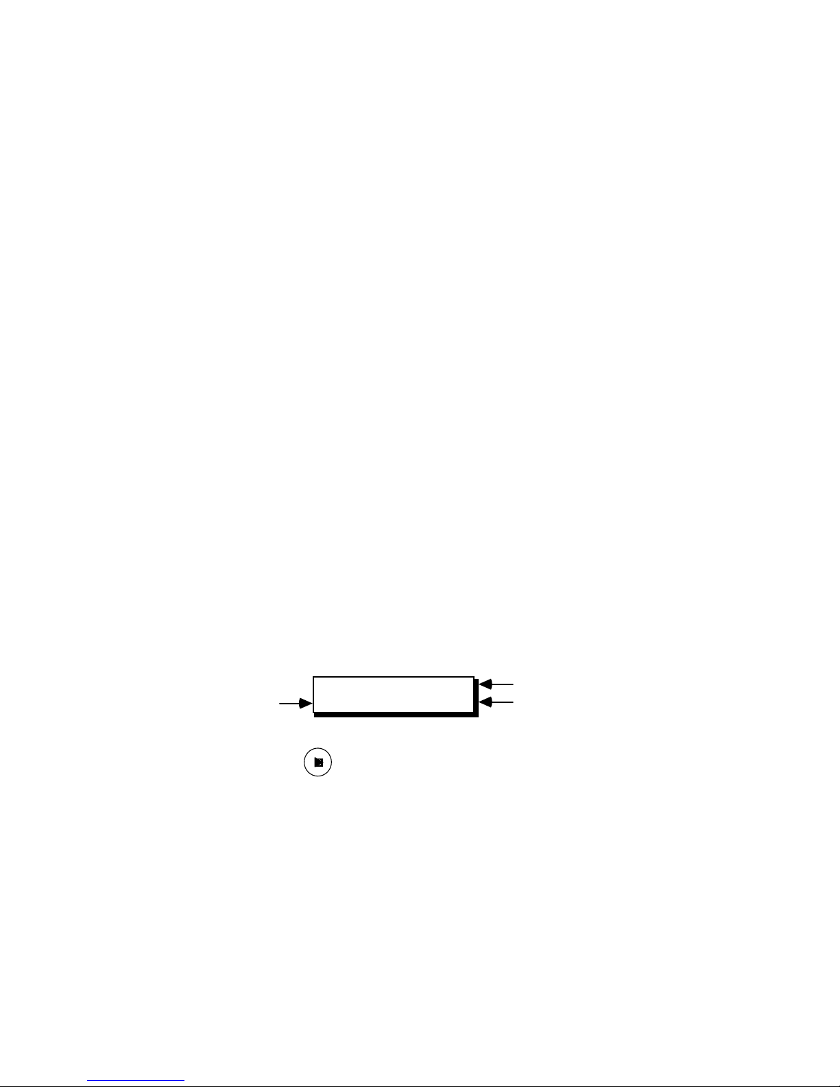
• If you have a mixer or switcher, attach a GPI cable from the GPI-M port to
the mixer.
• If you have a titler or other GPI device, attach a GPI cable from the GPI-T
port to the titler.
• Power on all connected equipment.
9. VCR Control—Testing and Troubleshooting
A. Setup
• Load a prerecorded video tape into each of your configured VCRs.
If you specified that LTC or VITC time code would be used and EXT
(external) was selected in the TCSRC (time code source field) field, ensure
that the tape you load has been striped with LTC or VITC.
If you specified that LTC, VITC or RCTC time code would be used and
INT (internal) was selected in the TCSRC field, ensure that your VCR is
configured to send the type of time code you selected and that the tape
has been striped with the selected time code.
• If your VCRs have a Master/Slave switch or menu setting, select Slave.
• If your VCRs have a Local/Remote switch, select Remote.
B. Test
For each VCR port you defined and connected (except for a record VCR
with IR control)—
• Press Edit Suite's A, B, C, D, or R key to select the VCR/camcorder to test.
The LCD changes to display the time code from the selected VCR.
VCR Protocol
Time Code
VCR Port
VCR 422
A 00:19:23.00
• Press the PLAY—
—transport key. The VCR should go into PLAY, and
the time value should begin to increment. If it does, the PROTO, VCR,
TCSRC and TC parameters are set correctly for this VCR and tape. Skip
Step C and repeat the test for your other VCRs.
C. Troubleshoot
• For RS-232 and RS-422 VCRs, press the VCR selector key (A, B, C, D or R),
then press [SHIFT]+[the STOP transport key]. This will send a
reinitialization command to your VCR.
• For RS-232 VCRs, verify the baud rate and character format parameters. If
these are correct, check your control cable for a null modem. If one is
Page 27

attached, remove it and try again. If one is not attached, add one and try
again.
• If you get an error message (LTC NOT FOUND or VITC NOT FOUND),
you specified LTC or VITC as the time-code type, but Edit Suite could not
find the time code on your tape.
- Advance to a different portion of the tape and try again, or try a different
tape.
- Verify that TCSRC=INT is selected if time code is sent through the Edit
Control Cable (most RS-232 and RS-422 VCRs only), or that TCSRC=EXT
is selected if the time code is sent by an audio or video cable attached to
the Time Code IN port.
- If the VCR can send multiple types of time code, ensure the correct type
is being sent.
- If the above do not work, change the configuration settings for this port
to TCSRC=INT and TC=NONE to see if Edit Suite can read the Real Time
Counter for the VCR.
• If the VCR does not go into PLAY or if the time code displays as **:**:**.**,
first verify that the control cable is attached to the correct port and VCR,
that power is applied to the VCR, and that there is a tape with video in the
VCR.
- Next verify that the PROTO, VCR, TCSRC, and TC fields are set
correctly. If not, correct them and try again.
• For all VCRs, if you selected VITC, LTC or RCTC time code, change your
settings to TCSRC=INT and TC=NONE to see if Edit Suite can control
your VCR with the Real Time Counter.
• Check Appendix A for additional VCR table numbers and try one of them.
• If the Time Code displays as 00:00:00.00 and does not move, you probably
have RCTC selected but no time code on the tape. Verify if the RCTC
exists on the tape. If not, use the VCR's PLAY WRITE function to add the
RCTC to the tape.
• Some VCRs—like the Sanyo GVR-S955—require a special cable. Refer to
Appendix B for the cable pinout requirements.
10. Creating, Previewing and Recording an A/A Roll
• All of the configuration information you entered earlier and the scenes
you are about to create are saved as soon as they are entered, so you can
take a break at any time, remove power from Edit Suite [if necessary],
then reapply power and resume where you left off.
Page 28
A. SELECT A SOURCE TO USE: Press the A, B, C or D key for one of the
A
A
sources you were able to control. (The A, B, C, and D keys are called the
VCR Selector keys.)
B. POSITION THE TAPE: Use the jog/shuttle or transport keys to move the
tape at least 45 seconds or one minute from the start of the tape.
C. CREATE A SCENE EVENT: Press and hold the [SHIFT] key, then tap the
[IN] key. A Scene Event for the current source is created (left figure). This
is the first event in your EDL (Edit Decision List). "001" is the event
number; "A" is the VCR port. The time is the time that was current on the
VCR when [SHIFT]+[IN] was pressed.
001 IN 00:05:22.04
A OUT : : .
D. ADJUST THE IN TIME: Use the transport keys or the jog/shuttle to
move the tape to a new location. While you do this the Scene Event is
replaced by the Live VCR display. The Live Display shows the current
source and the current time code. (If you want to see the Scene Event
again, press [OK].)
VCR PANA
00:05:24.00
001 IN 00:05:24.00
A OUT : : .
Live VCR Display Scene Event
Press [IN]. Edit Suite updates the value in the IN field to the VCR's current
time.
E. ADD AN OUT TIME: Move to an end position for the scene and press
[OUT]. Edit Suite adds the current tape address to the OUT field of the
active event.
001 IN 00:05:24.00
OUT 00:05:35.20
F. CREATE A SECOND EVENT: Press [SHIFT]+[IN] again to create a
second event. Adjust the IN and OUT times by positioning the tape and
pressing [IN] or [OUT].
G. SEARCH TO A POINT ON THE TAPE: This step has nothing to do with
creating an A/A Roll, but it's a function you should know exists. You can
have Edit Suite search to the IN or OUT point of any event by displaying
the event and pressing [GO TO]+[IN] or [GO TO]+[OUT]. Try it.
Page 29

H. DISPLAY THE FIRST EVENT IN THE LIST: Move to the first event in
the list (the top of the EDL) either by pressing the up arrow several times
or by pressing [GO TO]+[up arrow].
I. PREVIEW THE SCENES: Press [PREVIEW]. Edit Suite will—
• blink the POWER LED and turn off the other LEDs
• rewind the tape in your source VCR to a position in front of your first
scene
• cue the tape to move closer to the scene
• play until five seconds from the scene, then beep once to alert you that
your scene is about to start
• play your scene, beeping at the start of the scene and again at the end
of the scene.
Next, Edit Suite will display the second event in the LCD, and repeat the
above steps. After all scenes are complete, Edit Suite will beep three times,
stop blinking the POWER LED, and resume displaying/blinking the
ABCD LEDs.
J. RECORD THE SCENES: Load a tape in the record VCR. If your recorder
uses 422 protocol, follow the instructions in your VCR manual to prestripe
black on the tape, then position the tape about one minute (or more) from
the start. If your recorder is IR-controlled, put the VCR in Record Pause.
Press [GO TO]+[up arrow] to return to the first event, then press
[SHIFT]+[AUTO REC] to start recording. Again, the POWER LED will
blink and the other LEDs will be turned off. Edit Suite will beep once five
seconds before each scene, then three times when the auto-record is
completed. You can abort an auto record or a preview at any time by
pressing [ALL STOP] or the [Stop] transport key.
NOTE: If you inadvertently pressed [REC] instead of [SHIFT]+[AUTO REC],
the record VCR was started and a new event was created. This is called an
Assemble Edit and is described in Chapter 4. Press [ALL STOP] to stop all
VCRs, press [OK] to display the newly created event, then press
[DELETE]+[CUT] to delete the event. After the event is deleted, repeat Step J.
After the record is complete, press [ALL STOP] to stop the VCRs. ALL
STOP will not stop an IR-controlled VCR. You will have to take it out of
Record-Pause manually.
If you do not have a mixer or switcher or if you have only one source VCR, this
concludes the Getting Started section. Review Chapter 2, then read Chapters 4
and 5 to learn about assemble and auto-assemble editing and each type of
event that can be used with Edit Suite. To add accuracy to your edits, read
Chapter 7, Fine Tuning.
Page 30
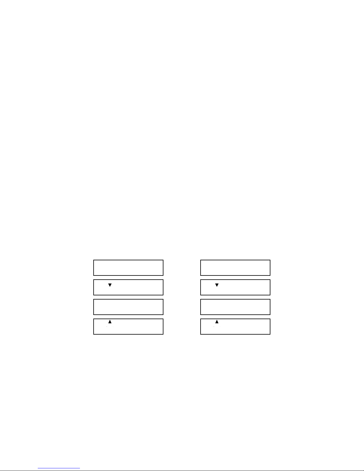
11. A/B Rolls—For Users With a Mixer or Switcher
A
A
A
A
A. DISPLAY THE LAST EVENT IN YOUR EDL: Press [down arrow] until
the second event you created is displayed, or press [GO TO]+[down
arrow].
B. CREATE A SCENE EVENT FOR A DIFFERENT SOURCE: Press the
VCR Selector key for one of your other sources, play that source to locate a
section of video to record, then press [SHIFT]+[IN] to create a new event.
Assuming you only had two events in your EDL, the new event is
assigned Event number 003.
C. ADD THE OUT TIME TO THE NEW EVENT: Use the jog/shuttle or
transport keys to move to the end of the video for the new scene and press
[OUT].
You now have three completed scenes in your EDL. All that is required to
create an A/B Roll is to add an MX1 or a MIXER Event between the last
two scene events.
D. DISPLAY EVENT 002: Use the up/down arrow keys to display the "A"
event for the A/B Roll. This should be event 002.
E. ADD AN MX1 OR MIXER EVENT: Press GPI-M (underneath the OUT
key). Depending on how you configured the GPI-M port in Step 7, either
an MX1 or a MIXER Event will be created between the last two scene
events. Your EDL should look similar to one of these lists.
001 IN 00:05:22.04
OUT 00:05:35.20
002 IN 00:07:05.12
OUT 00:07:17.00
002/003 FX=001 DI=>
MX1 SP=5 BG=0 BC=
003 IN 00:22:22.01
B OUT 00:22:45.10
001 IN 00:05:22.04
OUT 00:05:35.20
002 IN 00:07:05.12
OUT 00:07:17.00
002/003 TRANS DUR
MIXER 00:00:03.00
003 IN 00:22:22.01
B OUT 00:22:45.10
The arrows on events 002 and 003 indicate that these events are part of a
logical group. In this case, the group is scene event 002, the MX1 or
MIXER transition, and scene event 003.
In the MX1 Event, FX is the MX-1 transition number, DI is the direction,
SP is the speed, BG is the background color, and BC is the border color. A
blank for a border color indicates that a border is not used. The speed
determines the duration of the transition; this information is
preprogrammed in Edit Suite. When the scenes are recorded, Edit Suite
automatically sets up the MX-1 for the correct current and next sources.
Page 31

In the MIXER Event, you need to specify the duration of the transition in
seconds and frames. You do this by moving the cursor to the Duration
field, pressing CHG, typing the duration or turning the jog until the
correct duration is displayed, then pressing [OK]. For a cut to a new
source without a transition, specify a duration of 00. For a transition to a
new source, play the transition on your mixer, measure the duration for
the transition as accurately as possible, then enter the duration in the
MIXER Event. Also, you will need to ensure that the current and next
sources are set correctly at the mixer before the transition is run.
F. PREVIEW THE A/B ROLL: Display the last event in the EDL, then press
[PREVIEW]. Because you were on the last event when PREVIEW was
selected, only the last group of events will be previewed: scene 002, the
transition, and scene 003. To preview the entire EDL, move to the top of
the EDL before selecting PREVIEW.
G. RECORD THE A/B ROLL: Display the scene event from which you want
to start the recording, then press [SHIFT]+[AUTO REC]. Remember, if you
are using a third-party mixer, you will have to set up your mixer sources
manually. Also note that previews and auto-records always begin from
the first event in the current group. (If there are no events related to the
current event, it is a group consisting of a single event.) The only ways to
record scene 003 (above) by itself is to separate it from its current group by
removing the MX1 or MIXER event, or by adding a STOP event after the
MX1/MIXER event.
After the auto-record is complete, press [ALL STOP].
This concludes the Getting Started section. Review Chapter 2, then read
Chapters 4 and 5 to learn about assemble and auto-assemble editing and each
type of event that can be used with Edit Suite. To add accuracy to your edits,
read Chapter 7, Fine Tuning.
Page 32

Chapter 4 • Making a Production
There are two primary methods of making productions with Edit Suite: assemble editing and autoassemble editing.
In assemble editing, you start by making a rough recording of your production. Press [REC] at the start
point for each scene and press [OUT] at the end time for each scene. Each time you press [REC], Edit
Suite creates a new Scene Event and fills in the scene's IN time. Each time you press OUT, Edit Suite
pauses the recorder and fills in the OUT time for the event. After the rough recording is complete, so is
the first pass of the EDL.
Auto-assemble editing is the method used in Chapter 3, Getting Started, where you create Scene Events
for each scene you want in your production, add the MX1 or Mixer Events between the scenes, and then
press [SHIFT]+[AUTO REC] to have Edit Suite automatically assemble the production. You can also
add other events, such as GPI Events to trigger a titler or character generator, STOP Events to pause a
preview or auto-record, and INSERT and SPLT (split insert) Events to replace audio and/or video on a
prerecorded tape.
This chapter describes the steps to do assemble and auto-assemble editing. It also provides instructions
for reviewing the last recorded scenes, and provides hints to help improve your productions.
Assemble Editing
Before beginning an assemble edit, you should have a rough idea of which scenes you want to record
and the order in which you want them to appear in your production. The scenes may all be from one
source tape, or you can use several sources.
If you have multiple source tapes but only a single play VCR, use the NEW menu to add a STOP event
each time you need to change tapes. This way, if you later auto-assemble the production, Edit Suite will
pause the assembly whenever the tape needs to be changed.
Edit Suite does not preroll the VCRs during an Assemble Edit, so if your record VCR requires a preroll
(usually, this applies to RS-422 VCRs only) there will be glitches between each scene. If you later do an
auto-assemble edit of the same scenes, the glitches will be removed since an auto-assmeble with an RS422 as the record VCR prerolls the recorder.
To create an Assemble Edit–
1. If you are not using time code (RCTC, VITC, LTC), rewind your play VCRs/
camcorders and reset the counters before you begin marking scenes.
Page 33
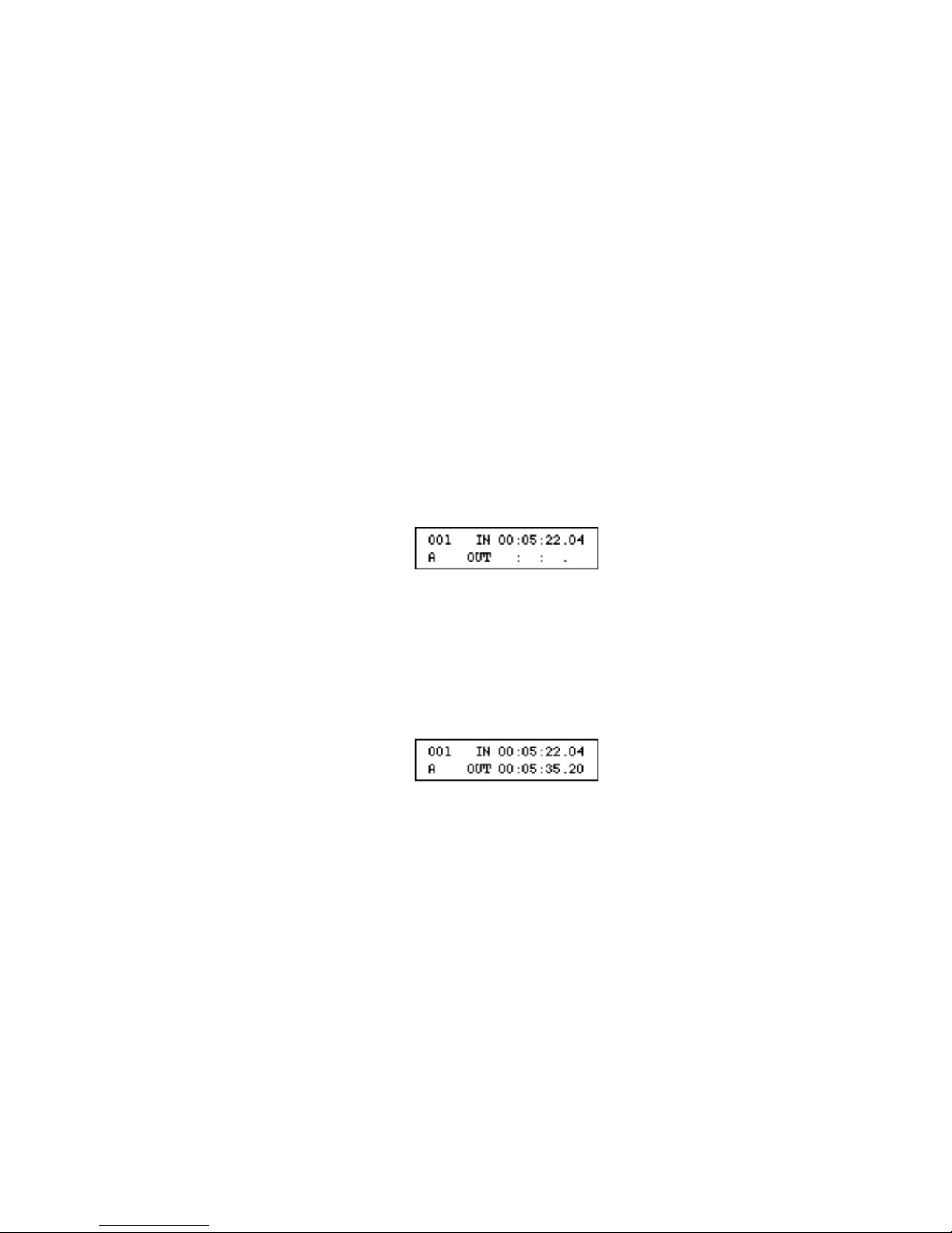
For VCRs/camcorders using PANA or LANC protocol, you can have Edit Suite do this by
pressing [GO TO] +[0 (zero)]. (Zero is the SETUP key.) For most VCRs using RS-232 or
RS-422 protocol, Edit Suite will rewind the tape but not rezero the counter.
2. Manually place the record deck into Record Pause. (Use Play Pause for RS-422 VCRs.)
3. Press the VCR selector key (A, B, C, D) for the source you want to record.
4. Use the jog/shuttle or the transport keys to locate the scene you want to record.
5. Position the tape a few seconds before the scene and press the [PLAY] transport key.
6. At the start of the scene, press [REC].
Edit Suite will put the record VCR into Record. It will also create a Scene Event and fill in
the IN time with the time code that was current on the play VCR when REC was pressed.
7. At the end of the scene, press [OUT].
Edit Suite will put the record VCR into Record Pause. It will also add the OUT time to the
event.
8. Repeat Steps 3 through 7 for any other scenes you want to record. Step 2 may be
omitted if the next scene is from the same source.
9. After all scenes have been recorded/created, press [ALL STOP] to stop all VCRs/
camcorders.
Auto-Assemble Editing
1. If you are not using time code (RCTC, VITC, LTC), rewind your play VCRs/
camcorders and reset the counters before you begin marking scenes.
For VCRs/camcorders using PANA or LANC protocol, you can have Edit Suite do this by
pressing [GO TO] +[0 (zero)]. (Zero is also the SETUP key.) For VCRs using 232 or 422
Page 34

protocol, Edit Suite will rewind the tape but not rezero the counter.
2. Create your Scene Events by–
- pressing the VCR Selector Key (A, B, C, D) for the source
- positioning the videotape to the start of the scene and pressing [SHIFT]+[IN] to
create the Scene Event and fill in the IN time
- positioning the videotape to the end of the scene and pressing [OUT] to fill in the
OUT time.
Other methods of creating Scene Events are described in Chapter 5.
3. Create Source Events for noncontrollable sources–like live feeds from a camera or solid
colors from the MX-1. Source Events are described in Chapter 5.
4. If you have a mixer or switcher and want to do an A/B Roll between some of your
scenes (rather than a straight cut), add an MX1 or MIXER Event between the scenes.
MX1 and MIXER Events are described in Chapter 5.
5. If you have a titler or other GPI device and want titles to play during some of your
scenes, add GPI-T Events at the locations you want the titles. GPI Events are described in
Chapter 5.
6. If you have multiple source tapes but only a single play VCR, add a STOP Event each
time you need to change tapes. Edit Suite will pause the assembly each time the tape
needs to be changed. STOP Events are described in Chapter 5.
7. In the EDL, use the up/down arrow keys to display the first event that you want to
record.
8. If your record VCR uses IR protocol, put the recorder into Record Pause.
9. Press [SHIFT]+[AUTO REC]. Edit Suite will auto-assemble your production.
Reviewing the Last Scene
To review the last scene that was recorded, press [SHIFT]+[REVIEW]. Edit Suite will select VCRR so
the transport keys and jog/shuttle can be used to control the VCR. It will then position the recorder a few
seconds ahead of the last scene that was recorded and play that scene.
Page 35

If the last scene that was recorded was an A/B Roll, the entire A/B Roll will be played.
You cannot do a review if the record VCR uses IR protocol.
Production Hints/Precautions
1. When you create a source or record tape, use SP speed. This will provide the best audio and
video quality and the best editing accuracy.
2. When you create a source tape, record 45-60 seconds of black at the start of the tape. In normal
use, Edit Suite cannot access scenes that start earlier than approximately 45 seconds from the
start of the tape.
3. When you create a source tape, shoot lots of footage. It is easy to edit out the bad footage, but
it is difficult to catch the exact frame you want if there is no usable footage around it.
4. If you have access to time code, use it. This will greatly improve the accuracy of your
productions.
5. If you have time code, it must be continuous or errors may occur.
6. If you do not have time code, rewind your tapes and rezero the counter before marking any
scenes. Rewind/rezero periodically as you are building the EDL.
Rewind and rezero again before beginning an auto-record.
7. If you have a mixer or a switcher, go easy on the number of A/B rolls you use. Most
productions use cuts between a majority of the scenes, and a transition every so often for effect.
See Match Frame Edits in the MX1 Events section of Chapter 5 for more information on A/B
Rolls.
8. If you have a titler, make sure your titles are started early enough so that they finish scrolling
before the scene ends. Otherwise, they may be "cut" in the middle of the scroll.
Page 36

The NEW Menu and Edit Suite Events
There are several methods of creating events with Edit Suite. Chapter 3 showed
you some methods of creating Scene and MX1 or MIXER Events. The NEW
Menu provides another method of creating each type of event.
This chapter starts by showing you how to display and use the NEW Menu to
create events. The later sections describe each type of event in detail.
There are eight types of events that can be created with Edit Suite. These are—
• Scene Events Identify the VCR or camcorder (A, B, C, D) that
contains the scene, and the starting (IN) and ending
(OUT) location for the scene.
• Sources Events Allow video from noncontrollable sources (SRC) to be
used in a production. Often used to include live video
from a camera or video device or, in conjunction with
the Videonics MX-1, to fade up from black.
• MX1 Events Used with the Videonics MX-1 to create A/B Rolls
between any of the VCRs, camcorders, or other
sources attached to the MX-1, or to create A/B Rolls
between a source and an MX-1 Color. Also used to do
AXA Rolls between scenes from a single video source.
• Mixer Events Used with third-party mixers or switchers to cut from
one source to another, and to create A/B Rolls
between any of the sources connected to the mixer.
• GPI Events Send commands to titlers, character generators, and
other GPI (general-purpose interface) devices.
• Insert (INS) Replace audio or video in the middle of a previously
recorded videotape with new audio and/or video
segments, while keeping the rest of the production
unchanged.
• Split Insert (SPLT) Allow audio to lead the video or video to lead the
audio during an audio/video insert.
• Stop Pause a preview or auto-record; separate one
production from another; calculate total running time
for a production.
Page 37
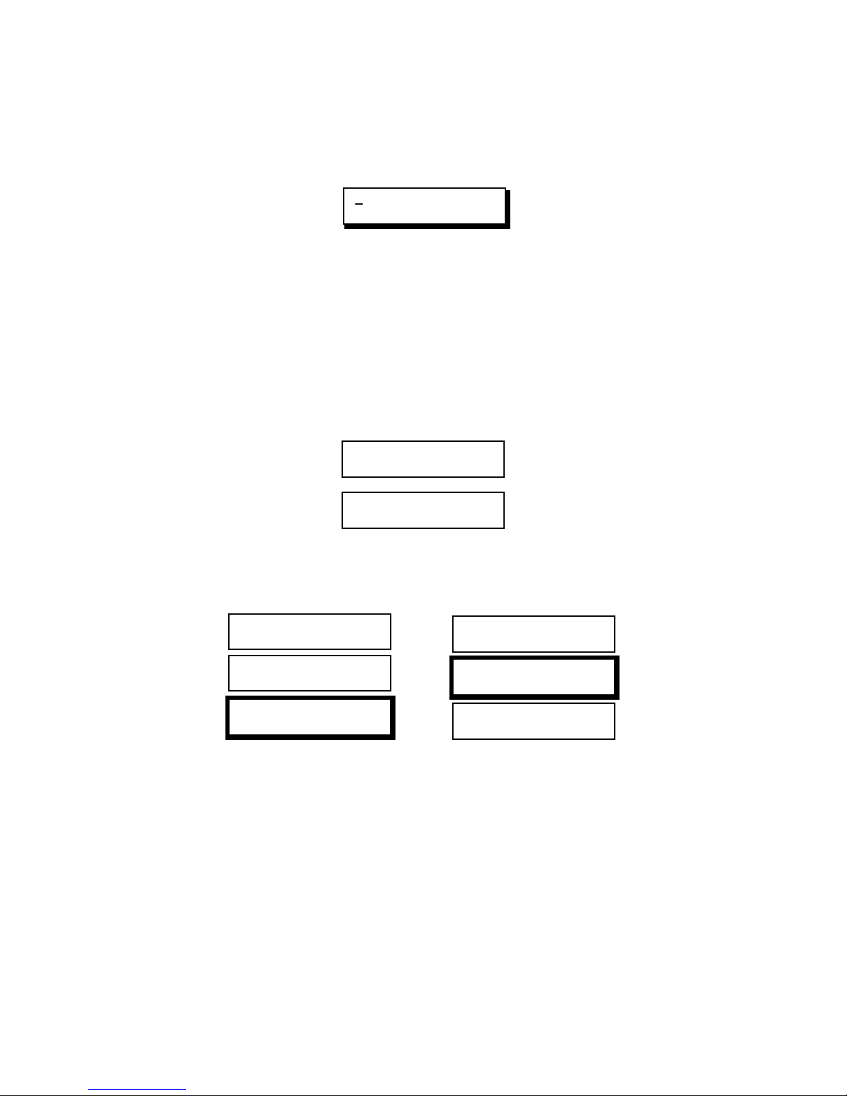
The NEW Menu
A
A
A
A
A
A
A
A
The NEW Menu (below) is used to create Edit Suite events.
MX1 A B C D SRC GPI
MIXER SPLT INS STOP
You can display the NEW Menu at any time except when in the SETUP menus or
when a Preview, Auto Record, or Review is in progress.
To display the NEW Menu, press [NEW] (numeric key 1).
An alternate method of displaying the menu is to press [SHIFT]+[NEW].
The difference between these two methods is the order in which Edit Suite places
the new event. For example, assume you have already created the following two
Scene Events, and that the second event—event 002—is showing in the Edit Suite
display.
001 IN 00:05:22.04
OUT 00:05:35.20
002 IN 00:07:05.12
OUT 00:07:17.00
If you press [NEW] to display the NEW Menu, the new event will be added
immediately after event 002. If you use [SHIFT]+[NEW], the new event will be
added immediately before event 002, as shown below.
001 IN 00:05:22.04
OUT 00:05:35.20
002 IN 00:07:05.12
OUT 00:07:17.00
003 IN : : .
OUT : : .
001 IN 00:05:22.04
OUT 00:05:35.20
003 IN : : .
OUT : : .
002 IN 00:07:05.12
OUT 00:07:17.00
NEW SHIFT+NEW
Note the numeric sequence for the event numbers in the right-hand column—
001, then 003, then 002. When a new event is created, Edit Suite assigns the next
available number to the new event without changing the numbers of previouslycreated events. This way, once you create an event, that event number will
always contain the same information no matter where it is located in the list.
During a preview or an auto-record, Edit Suite processes the events in the order
they appear in the list—not based on their event numbers. If you want to, you
can manually change the event numbers or you can issue a command to Edit
Suite to have it automatically renumber all of the events. The procedure to do
this is described in the Renumbering all Events in the EDL section of Chapter 6.
Page 38

To create an event with the NEW Menu
1. Press [NEW] or [SHIFT]+[NEW] to display the NEW Menu.
MX1 A B C D SRC GPI
MIXER SPLT INS STOP
2. Use the left/right/up/down arrow keys to move the cursor to the event
type you want to create.
3. Press [OK] to create the event. (See the following sections for a more
detailed description of each type of event.)
To exit the NEW Menu without creating an event
• Press [NEW] again. The event that was being displayed when the NEW
Menu was selected will be redisplayed.
Note: If there are not any events currently created, the NEW Menu will
remain displayed until you do one of the following—
- create an event
- access the SETUP Menus
- use Edit Suite to select/control a VCR/camcorder attached to a
configured VCR port.
Page 39
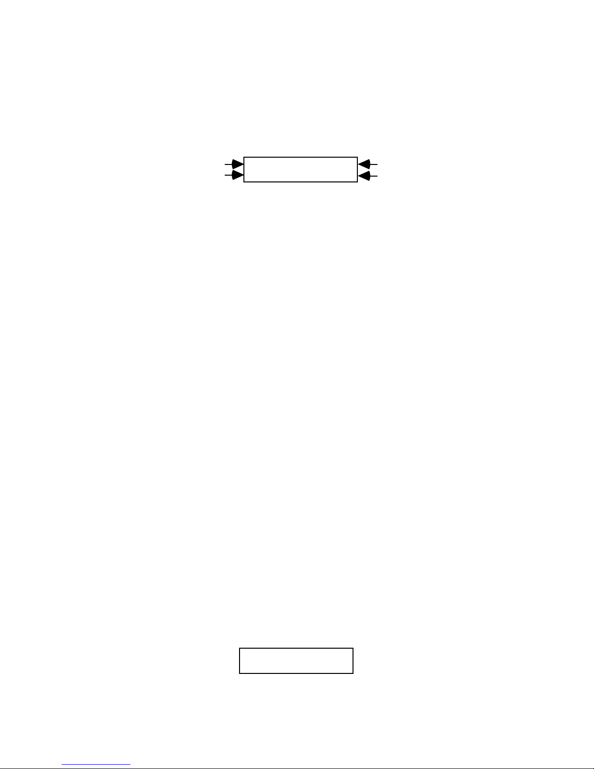
Scene (A/B/C/D) Events
Scene Events are the most common events in an EDL and the most important
ones. They identify which VCR contains the footage you want to record and the
starting and ending locations for that footage.
Event Number
VCR Port
001 IN 00:05:22.04
A OUT 00:05:35.20
Starting Location
Ending Location
The starting location is called the Edit IN time; the ending location is called the
Edit OUT time. Times are shown in an hours:minutes:seconds.frames format,
with 30 frames per second in an NTSC system (North America, Japan) and 25
frames per second in a PAL system (Europe, Asia).
You can create an entire production with nothing more than Scene Events from a
single source tape. Edit Suite will locate the first scene, record the video, cut to
the second scene, record that video, and continue processing your Scene Events
until they are all recorded.
If you have a Videonics MX-1 mixer, you can create Scene Events from two, three
or even four different sources. Edit Suite will switch control from one VCR to the
next when the video source changes, and it will automatically switch the output
of the MX-1 to that same source. And still, the only events you need to create to
do this are Scene Events.
If you have a third-party mixer or switcher, you will need to add a MIXER Event
between your Scene Events when the video source changes from one VCR to
another. See Mixer Events later in this chapter.
A/B Rolls? These depend on your Scene Events, too. To do an A/B Roll, you just
create two Scene Events from different sources and put an MX1 or MIXER Event
between the them.
Creating a Scene Event
There are three ways to create a Scene Event:
1. The NEW Menu
• Display the NEW menu, select A, B, C, or D—depending on which source
has the video you want to add—then press [OK]. Edit Suite will make the
VCR port you selected the current port, then create a Scene Event with
empty IN and OUT times.
001 IN : : .
A OUT : : .
Page 40
The lights above the A, B, C, D keys are used to indicate which source is
A
A
current. If only one light is lit—whether it is blinking or steady—that is the
current source. If two LEDs are lit, the one that is steady indicates the
current source.
2. Using the VCR Selector Keys
• Press [SHIFT]+[A], [B], [C], or [D]. Edit Suite follows the same procedure
as if you create the event with the NEW menu.
3. Using the IN or OUT Keys
A. If the source you want to use is not already the current source, press the
[A], [B], [C] or [D] selector key.
B. Press [SHIFT]+[IN] or [SHIFT]+[OUT]. A Scene Event for the current
source is created with the IN or OUT time filled in (depending on which
key you pressed).
001 IN 00:05:22.04
OUT : : .
001 IN : : .
OUT 00:05:35.20
SHIFT+IN SHIFT+OUT
Completing/Changing the IN/OUT Times
When the Scene Events are created, either the IN time, the OUT time, or both
times are empty. To fill in the IN/OUT times, either—
• Use the transport keys and the jog/shuttle to move the tape to the desired
IN/OUT time and then press [IN] or [OUT]. If the time was already filled
in, it is updated to the current time for the source.
or
• Move the cursor to the IN/OUT field, press [CHG] to activate the numeric
keys, then type in the desired time code.
If you make a mistake before you have completed your entry, press
[CHG] once to revert to the old value, press [CHG] again to reactivate the
numeric keys, then re-attempt the entry.
If you enter, for example, 90 in the seconds field, it is automatically
converted to one minute and 30 seconds.
Hints for numeric entry
1. If you have to change only one or two numbers in an existing time code,
after pressing [CHG] you can move to a specific digit within the time code
by pressing [SHIFT]+[left/right arrow]. Next, change the number and
press [OK] to save your change.
Page 41

2. You can always leave a numeric entry field before entering all the digits by
pressing [OK]. If the remaining positions were blank, they are filled with
zeroes. If the remaining positions were already assigned values, the old
values are retained.
3. You can use the jog/shuttle to increment/decrement changes to the time
code. To do this, press [CHG] to activate change mode, turn the
jog/shuttle until the desired time is displayed, then press [OK]. The jog
will work only if the shuttle is in the Pause position.
OUT Time Before IN Time
If you enter an OUT time that is earlier than your IN time, Edit Suite will beep
twice when it saves the information. If you hear this beep, look carefully at the
time codes you entered and correct the error.
If you do not correct the error, when you later attempt to preview or record the
scene, Edit Suite will halt the preview or auto-record when it tries to process the
event, and will display error message 01: Out pt before in pt. Clear the message by
pressing [OK], then correct the error.
Adding Accuracy to the IN and OUT Times
Whether you use time code or not, the best tip for maintaining both accuracy and
quality is to shoot all of your footage and record all of your productions using
the SP tape speed setting on your camcorder or VCR.
If you have time code (VITC, LTC or RCTC), as long as the time-code data
remains readable, your scenes will be accurate.
If you do not have time code, there are two procedures to follow to help maintain
accuracy.
• Rewind the source tapes and rezero the VCR counter before you mark any
scenes, and repeat the rewind/rezero procedure periodically while you are
marking scenes. For VCRs and camcorders using PANA or LANC protocol,
pressing [GO TO]+[zero] will rewind the tape for the selected VCR and
rezero the counter. Pressing any key while the rewind/rezero procedure is in
progress will abort the procedure.
• Unless your VCR displays frames along with its hours, minutes and seconds
information, mark your scenes while the VCR is in Play speed. If a scene is
marked while the video is playing, Edit Suite can interpret the time between
each second to arrive at a frame value—even though the VCR doesn't provide
any frame information.
If the tape is played at a jog or slow shuttle speed, the counter on the VCR
does not increment (or does not increment accurately) so Edit Suite cannot
estimate which frame value to use. Consequently, the time code will be
recorded as hours, minutes, seconds, and 00 frames.
Page 42
Refer to Appendix D, Edit Control Chart, for more information about time code
A
and edit accuracy.
Changing the VCR Port
If you need to change the VCR port for a Scene Event, use the arrow keys to
move the cursor to the VCR Port field, then press [CHG] enough times to display
the desired port—A, B, C or D.
Event Number
VCR Port
001 IN 00:05:22.04
OUT 00:05:35.20
Changing the Event Number
If you want to change the Event Number for a Scene Event, use the arrow keys to
move the cursor to the Event Number field, press [CHG] to activate the numeric
keys, then type in the desired number (or use the jog/shuttle and press [OK]).
The number may be any three-digit value from 001 through 999. If there is
already another event with the number you enter, Edit Suite will beep once and
redisplay the old event number.
You can have Edit Suite renumber all of your events automatically by pressing
the key combination [GO TO]+[SHIFT]+[CHG]. Renumbering events from 1 to
the end is often called Ripple Down. Chapter 6 provides more information on the
renumbering function.
Page 43
Source (SRC) Events
Source Events are used to record video from noncontrollable sources, such as
color bars from a pattern generator, live scenes from a video camera or
background colors from the Videonics MX-1.
Event Number
Source Tile Identifier
002 DUR 00:00:30.00
SRC D
Duration
VCR Port
Event Number
Source Tile Identifier
002 DUR 00:00:30.00
SRC COL=0
Duration
If COL, MX1 Color to use
Because the sources are noncontrollable, there is no time-code entry. Instead, you
specify a duration for the event.
Generally, Source Events are used only by customers who have a mixer or
switcher. You connect the audio/video feeds from the source to your mixer and
define the corresponding port on Edit Suite as PROTO=NONE. No cables are
connected between the device and Edit Suite. At the appropriate time in your
production, Edit Suite will send a command to the mixer/switcher to transition
or cut to the source, and will then record or preview the video from that source
for the specified duration.
Fade Up From Black
If you use a Videonics MX-1, you can access the MX-1 background colors via a
Source Event. You specify the color you want to use and the duration of the
scene, and Edit Suite will send commands to the MX-1 at the appropriate time to
transition to or from the color. A Source Event is often used in combination with
an MX1 Event at the start of the production to record a fade up from black. To do
this, create a Source Event with COL=0, add an MX1 Event with BC=0, and
follow with a Scene Event. The background color you select for the Source Event
and the background color you select for the MX1 Event must be the same.
SRC Events Without a Mixer/Switcher
Without a mixer or switcher you cannot automatically cut from your play source
to a noncontrollable source. However, if you add a STOP event each time you
want to switch from one source to another, Edit Suite will pause your recording
when it detects the STOP event. This way—with the recorder paused—you can
change which device is connected to the recorder and then resume the
production by displaying the next event to be recorded and pressing
[SHIFT]+[AUTO REC].
Page 44
SRC Event Precaution
If the first
event in an auto-record is a SRC event and if the record VCR is not
already in Record Pause, either put it into Record Pause manually before starting
the auto-record or add two or three seconds to the duration for the event. This is
why—
• Near the start of an auto-record Edit Suite issues a Record Pause
command to the record VCR.
• A few moments later, Edit Suite asks the record VCR what mode it is in.
Many VCRs respond that they are in Record Pause—even though they
may still be transitioning from Stop to Record Pause.
• Having been told that the VCR is already in Record Pause, Edit Suite
issues the Record command to begin recording—but because the recorder
was not really in Record Pause, until it gets there and then processes the
Record command, the first few seconds of video from the Source Event
will not be recorded.
The amount of error varies from VCR to VCR, but is never more than about two
or three seconds. The problem does not occur with Source Events that are not the
first events in an auto-record, since the record VCR will already be in Record
Pause.
Ways of Creating a Source Event
There are three ways of creating a Source Event:
1. The NEW Menu
• Display the NEW menu, select SRC, then press [OK]. Edit Suite will create
a Source Event with COL=0 as the default.
002 DUR : : .
SRC COL=0
2. Using the VCR Selector Keys
• Press [SHIFT]+[A], [B], [C], or [D] for any port whose protocol is set to
NONE. Edit Suite will create a Source Event for that source.
3. Using the COLOR Key (Videonics MX-1 users only)
• Press [SHIFT]+[COLOR]. Edit Suite will create a Source Event with
COL=0.
Entering/Changing the DUR (Duration)
To change the duration of a SRC event:
• Move the cursor to the DUR field, press [CHG] to activate the numeric
keys, then enter the desired duration.
Page 45
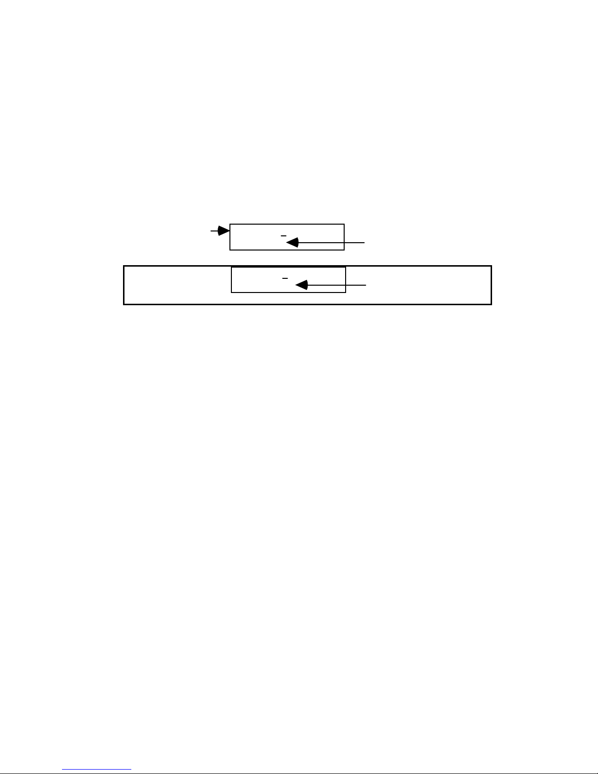
or
• Move the cursor to the DUR field, press [CHG], use the jog/shuttle to
increment/decrement the duration, then press [OK]. (Note that the jog
cannot be used unless the shuttle is in Pause.)
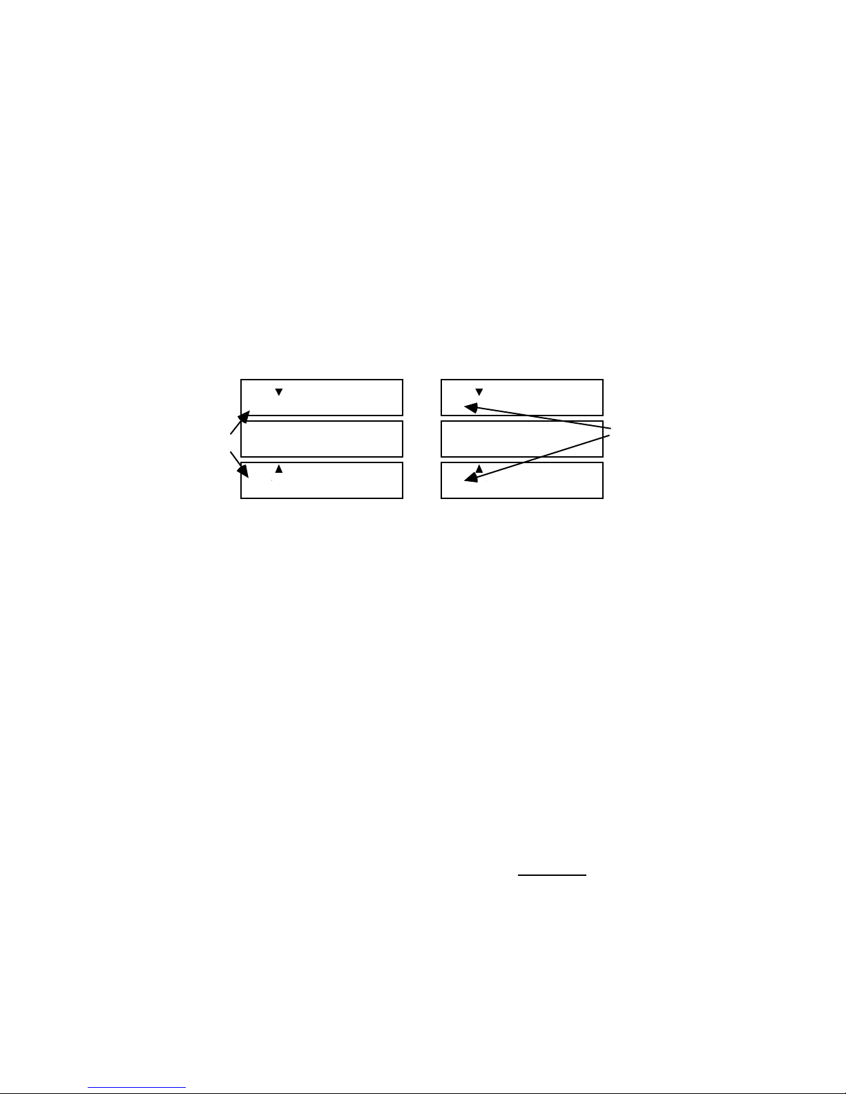
Changing the VCR Port or MX-1 Color
To change the source, use the arrow keys to move to the VCR Port field, then
press [CHG] repeatedly until the desired source is displayed. The choices are A,
B, C, D and COL. COL (color) applies to Videonics MX-1 users only and is used
to specify that an MX-1 background color will be used.
Event Number
002 DUR 00:00:30.00
SRC D
002 DUR 00:00:30.00
SRC COL=0
VCR Port
If COL, MX-1 Color to use
If COL is selected, you are also given a choice of which color to use. To change
the choice for color, move the cursor to the color value field (0 above), press
[CHG] and type the value. The values are the same as those used with the MX-1:
0=Black, 1=White, 2=Gray, 3=Red, 4=Yellow, 5=Green, 6=Bright Blue, 7=Light
Blue, 8=Purple, 9=User-defined.
Changing the Event Number
To change the Event Number, use the arrow keys to move the cursor to the Event
Number field, press [CHG] to activate the numeric keys, then type in the desired
number (or use the jog/shuttle and press [OK]).
The number may be any three-digit value from 001 through 999. If there is
already another event with the number you enter, Edit Suite will beep and
redisplay the old event number that was assigned.
Page 46
MX1 Events
A
A
A
MX1 Events are available to Videonics MX-1 users only. MX1 Events are used to
create A/B Rolls between scenes from two play VCRs or AXA Rolls between
scenes from the same VCR. In an A/B Roll, instead of cutting from one scene to
the next, a fade, wipe, dissolve or other special effect can be used. During the
transition from one source to the next, both sources are played, displayed and
recorded simultaneously.
To specify an AXA Roll, add an MX1 Event between two scenes from the same
VCR. Because both scenes are from the same VCR, a video freeze is done at the
OUT point of the first scene, and the transition to the second scene begins from
the frozen scene.
Same Source
002 IN 00:07:05.12
OUT 00:07:17.00
002/003 FX=001 DI=>
MX1 SP=5 BG=0 BC=
003 IN 00:12:15.00
OUT 00:12:56.10
002 IN 00:07:05.12
OUT 00:07:17.00
002/003 FX=001 DI=>
MX1 SP=5 BG=0 BC=
003 IN 00:22:22.01
B OUT 00:22:49.10
Different
Sources
AXA Roll A/B Roll
To specify an A/B Roll, add an MX1 Event between two Scene Events from
different VCRs. In the above example, scene 002 is from VCR A and scene 003 is
from VCR B.
The arrows on events 002 and 003 indicate that the events are part of a logical
group. In this case, the group is the scene from event 002, the MX-1 transition,
and the scene from event 003.
In the MX1 Event above, the event number—002/003—reflects the event
numbers of both sources in the AXA and A/B Rolls. FX is the MX-1 transition
number, DI is the direction for the transition, SP is the transition speed, BG is the
background color, and BC is the border color. A blank for a border color
indicates that a border color is not used.
When the above sequence is previewed or auto-recorded, Edit Suite sends
commands to the MX-1 to tell it which source to make current and which to make
next, and then sends all the transition information.
For A/B Rolls, the transition will be timed so that the midpoint
is the OUT point for the "A" source and the IN point for the "B" source. You can
adjust where the "B" source in an A/B Roll begins by changing the IN OFFSET
parameter for the associated play VCR. Refer to Chapter 7, Fine Tuning, for more
information.
For an AXA Roll, the only setup difference is that you place the MX1 Event
between two scenes from the same source. For transition timing, the start point
of the transition
Page 47
of the transition in an AXA Roll is the OUT point for the first scene and the IN
A
A
point for the second scene.
Match Frame Edits
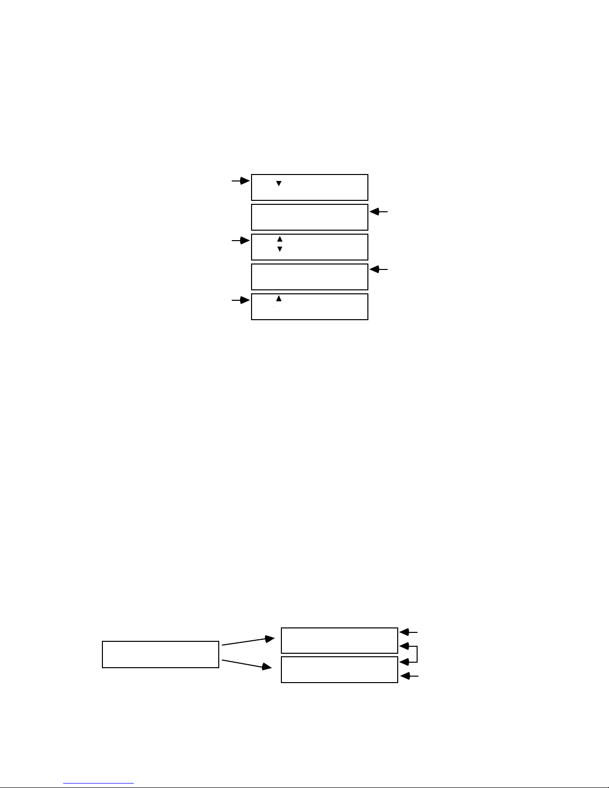
Edit Suite does Match Frame Edits whenever back-to-back A/B Rolls are
specified in the Edit Decision List.
Scene or Source
Event
Match Frame Event
(Scene or Source)
Scene or Source
Event
001 IN 00:07:05.12
OUT 00:07:27.00
001/002 FX=001 DI=>
MX1 SP=5 BG=0 BC=_
002 IN 00:22:20.00
B OUT 00:22:40.00
002/003 FX=016 DI=>
MX1 SP=4 BG=4 BC=
003 IN 00:12:04.04
OUT 00:13:20.00
A/B Roll (MX1
or Mixer Event)
A/B Roll (MX1
or Mixer Event)
The above example instructs Edit Suite to do an A/B Roll between events 001
and 002, and then to do a second A/B Roll between events 002 and 003. For the
first A/B Roll, event 002 is the "B" source for the roll; for the second A/B Roll,
event 002 is the "A" source for the roll.
Before the first A/B Roll is done, Edit Suite synchronizes the video for events 001
and 002 by prepositioning the video for event 002 to its preroll position. This
way, Edit Suite knows when to begin rolling the "B" source so that it will be
playing the correct video when the MX-1 or Mixer transition occurs.
In order to do the second A/B Roll, the video for events 002 and 003 needs to be
synchronized. Since the video from event 002 will already be playing, VCR B
must be paused while the video for event 003 is located and positioned. The
location where event 002 is paused is the Match Frame location.
To Edit Suite, event 002 is treated as two separate events: the first event has the
same IN time as event 002; the second event has the same OUT time as event 002.
The position where event 002 is paused—the Match Frame position—becomes
the OUT time for the first half of event 002 and the IN time for the second half of
event 002*.
002 IN 00:22:20.00
B OUT 00:22:40.00
EDL Event
002 IN 00:22:20.00
B OUT 00:22:30.00
002* IN 00:22:30.00
B OUT 00:22:40.00
How Edit Suite Treats the Event
Same IN Time
Match Frame at
Approx. Mid Time
Same OUT Time
Page 48
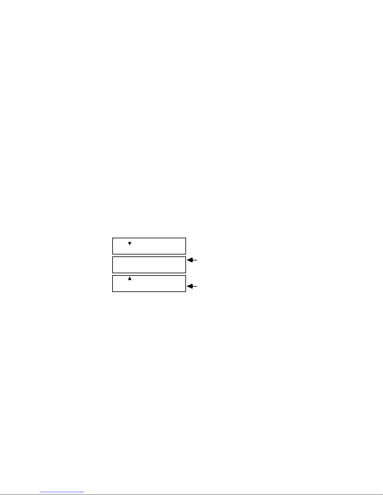
The Match Frame occurs at approximately the midtime of the scene, but may
A
occur earlier or later depending on the duration of the scene and the speed or
duration of the MX1 or MIXER Events.
Edit Suite will attempt to begin recording the second half of event 002 at the
exact frame where the first half of event 002 ended; however, the match frame
will only be as accurate as your VCRs and camcorders allow. If you have frame
accurate VCRs and time code, the match frame can be exact so that in your final
recording there are no missing or repeated frames around the match frame
position. If your VCR/camcorders are not frame accurate, there may be a few
frames of underlapping or overlapping video at the point of the match frame.
If your VCRs are not frame accurate, you can minimize the impact of any match
frame error by manually splitting event 002 in the preceding example into two
scenes and selecting a match point where there is non-critical video and a pause
in the audio.
Simultaneous Rolling of Two VCRs
You can roll two VCRs simultaneously by placing an MX1 or MIXER Event
between two Scene Events, leaving the OUT time for the second Scene Event
blank, and pressing [PREVIEW] or [SHIFT]+[AUTO REC].
002 IN 00:07:05.12
OUT 00:07:17.00
002/003 FX=000 DI=>
MX1 SP=4 BG=0 BC=
003 IN 00:22:22.01
B OUT : : .
Select a CUT or a highspeed transition
Leave OUT time blank
The OUT time for the first event and the IN time for the second event should be
the positions where the video from the two sources needs to be synchronized. To
fine-tune the point where the "B" source starts playing, adjust the IN OFFSET for
the "B" source's VCR port as described in Chapter 7, Fine Tuning.
If you inadvertently fill in the OUT time for the second source, either delete the
event and create a new one or change the OUT time to a high value—like
23:00:00.00.
Setup and Precautions
Before you can perform an MX-1 transition from Edit Suite, the GPI-M parameter
in the CONFIG menu must be set to MX-1, and the MX-1 must be attached to
Edit Suite's GPI-M port. Use the GPI cable provided with Edit Suite to connect
the two devices. If a different cable is used, make sure it is a stereo cable.
Page 49

If you are transitioning to or from an MX-1 Color, ensure that the color for the
Source Event and the background color for the transition are the same.
If you specify a slow speed for a transition, ensure that your scenes are long
enough to complete the transition before the scene ends.
Ways to Create an MX1 Event
There are two ways to create an MX1 Event:
1. The NEW Menu
• Display the NEW menu, select MX1, then press [OK]. Edit Suite will create
an MX1 Event using the default values shown below.
002/003 FX=001 DI=>
MX1 SP=5 BG=0 BC=
2. The GPI-M Key
• Press GPI-M. An MX1 Event will be created using the field values that
were selected on the MX-1 at the time the GPI-M button was pressed.
002/003 FX=187 DI=<
MX1 SP=4 BG=6 BC=4
If the event is placed between existing scene or Source Events, those
events are used as the current and next sources for the transition. If the
MX1 Event is placed after an last scene or Source Event in the EDL, Edit
Suite will create a new Scene Event automatically. The next source on the
MX-1 will be the source for the new event.
If the connection between Edit Suite and the MX-1 is not active (cable
missing, MX-1 powered off, etc.) when the GPI-M key is pressed, an error
message, Error 21. No MX-1 found, is displayed. Press [OK] to clear the
error message, then complete the necessary connections.
Page 50

Changing MX1 Event Fields
To change the MX1 Event fields:
002/003 FX=001 DI=>
MX1 SP=5 BG=0 BC=
• Move the cursor to the FX (transition number) field. Press [CHG] to
activate the numeric keys, then enter the three-digit transition number.
Any of the MX-1's 240 transitions (000-239) may be used.
• Move the cursor to the DI (transition direction) field. If you want to
change the direction for the transition, press [CHG].
• Move the cursor to the SP (speed) field. To change the value, press [CHG]
to activate the numeric keys, then use the numeric keys or the jog/shuttle
to change the value. If you use the jog/shuttle, complete your entry by
pressing [OK].
• Move the cursor to the BG (background color) field. To change the value,
press [CHG] to activate the numeric keys, then use the numeric keys or
the jog/shuttle to change the value.
• Move the cursor to the BC (border color) field. To change the value, press
[CHG] to activate the numeric keys, then use the numeric keys or the
jog/shuttle to change the value.
To specify that a border color will not be used, press [CHG], then press
[DELETE].
Page 51
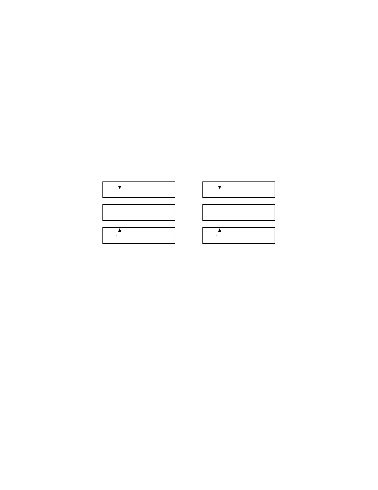
Mixer Events
A
A
Use MIXER Events only if you have a third-party mixer or switcher attached to
Edit Suite's GPI-M port.
Mixer Events are used to cut from one source to another and to create A/B Rolls
between scenes from two play VCRs. In an A/B Roll, instead of cutting from one
source to the next, a fade, wipe, dissolve or other special effect is used. During
the transition between sources, both sources are played, displayed and recorded
simultaneously.
To specify a cut to a scene from a new source, add a MIXER Event with a
transition duration (TRANS DUR) of 00 between the two Scene Events. To
specify an A/B Roll, add a MIXER Event between two Scene Events, and include
the length of time it takes for the transition to run in the TRANS DUR field.
002 IN 00:07:05.12
OUT 00:07:17.00
002/003 TRANS DUR
MIXER 00:00:00.00
003 IN 00:22:22.01
B OUT 00:22:45.10
002 IN 00:07:05.12
OUT 00:07:17.00
002/003 TRANS DUR
MIXER 00:00:03.20
003 IN 00:22:22.01
B OUT 00:22:45.10
Cut to New Source A/B Roll to New Source
The arrows on events 002 and 003 indicate that the events are part of a logical
group. In this case, the group is the scene from event 002, the MIXER Event, and
the scene from event 003.
In the MIXER Event above, the event number—002/003—reflects the event
numbers of both sources in the Cut or A/B Roll. TRANS DUR is the length of
time—in hours, minutes, seconds, and frames—that the transition will run. Edit
Suite needs this information so it can determine the correct time to start playing
the A/B Roll's "B" source and the correct time to send the transition command
(GPI pulse) to the mixer/switcher.
To determine the transition duration, play the transition on your mixer at the
speed you want to use and measure the length of time it takes to complete. If you
have a window dub or a recording of a clock or stopwatch, you can record the
transition and then subtract the end time from the start time. (Hint: Create a table
of durations for the various transition speeds used by your mixer.)
An A/B Roll will be timed so that the midpoint of the transition is the OUT point
for the "A" source and the IN point for the "B" source. You can fine-tune the
starting time for the "B" source in an A/B Roll by changing the IN OFFSET
Page 52

parameter for the associated VCR. This parameter is accessed from the
Configuration Menu.
Before previewing or recording a cut or transition, you must manually set up or
preprogram the mixer/switcher for the cut or A/B Roll's "A" source, "B" source,
transition type, etc.
If you have a preprogramming feature to set up the sources and transitions, but
you have to many transitions to store in your mixer/switcher memory, you can
use Edit Suite STOP Events to break your production into two or more parts. See
STOP Events later in this chapter.
For information about Match Frame Edits and Simultaneous Rolling of Two
VCRs, refer to the MX1 Event description (previous section).
Setup and Precautions
Before you can run a MIXER transition from Edit Suite, the GPI-M parameter in
the CONFIG menu must be set to MIXER.
The GPI-M MX OFFSET parameter is used to adjust the time Edit Suite sends the
cut/transition command to the Mixer. If the cuts and transitions are always a
little late, make the offset value larger. If they are always a little early, make the
offset value smaller. The offset is in 1/8 frame increments, so a value of 0008
adjusts the timing by one frame. A value of 0240 (NTSC=8x30) or 0200
(PAL=8x25) adjusts the timing by one second.
The mixer/switcher must be attached to Edit Suite's GPI-M port. Use the GPI
cable provided with Edit Suite to connect the two devices.
If a slow transition (long duration) is used, ensure that your scenes are long
enough to complete the transition before the scene ends.
Ways to Create a MIXER Event
There are two ways to create a MIXER Event:
1. The NEW Menu
• Display the NEW menu, select Mixer, then press [OK]. Edit Suite will
create a MIXER Event with a transition duration of zero (00).
002/003 TRANS DUR
MIXER 00:00:00.00
2. The GPI-M Key
• Press GPI-M. A MIXER Event will be created with a transition duration of
zero (00).
If the event is placed between existing scene or Source Events, those
events are used as the current and next sources for the transition. If the
Page 53
MIXER Event is placed after the last scene or Source Event in the EDL,
Edit Suite will create the new event automatically. Edit Suite's next source
will be the source for the new event. To set a next source, press [GO
TO]+[A, B, C, or D].
Changing the MIXER Transition Duration
To change the MIXER Transition Duration:
002/003 TRANS DUR
MIXER 00:00:00.00
• Press [CHG] to activate the numeric keys.
• Use the numeric keys or the jog/shuttle to change the value. If you use the
jog/shuttle, complete your entry by pressing [OK].
Page 54
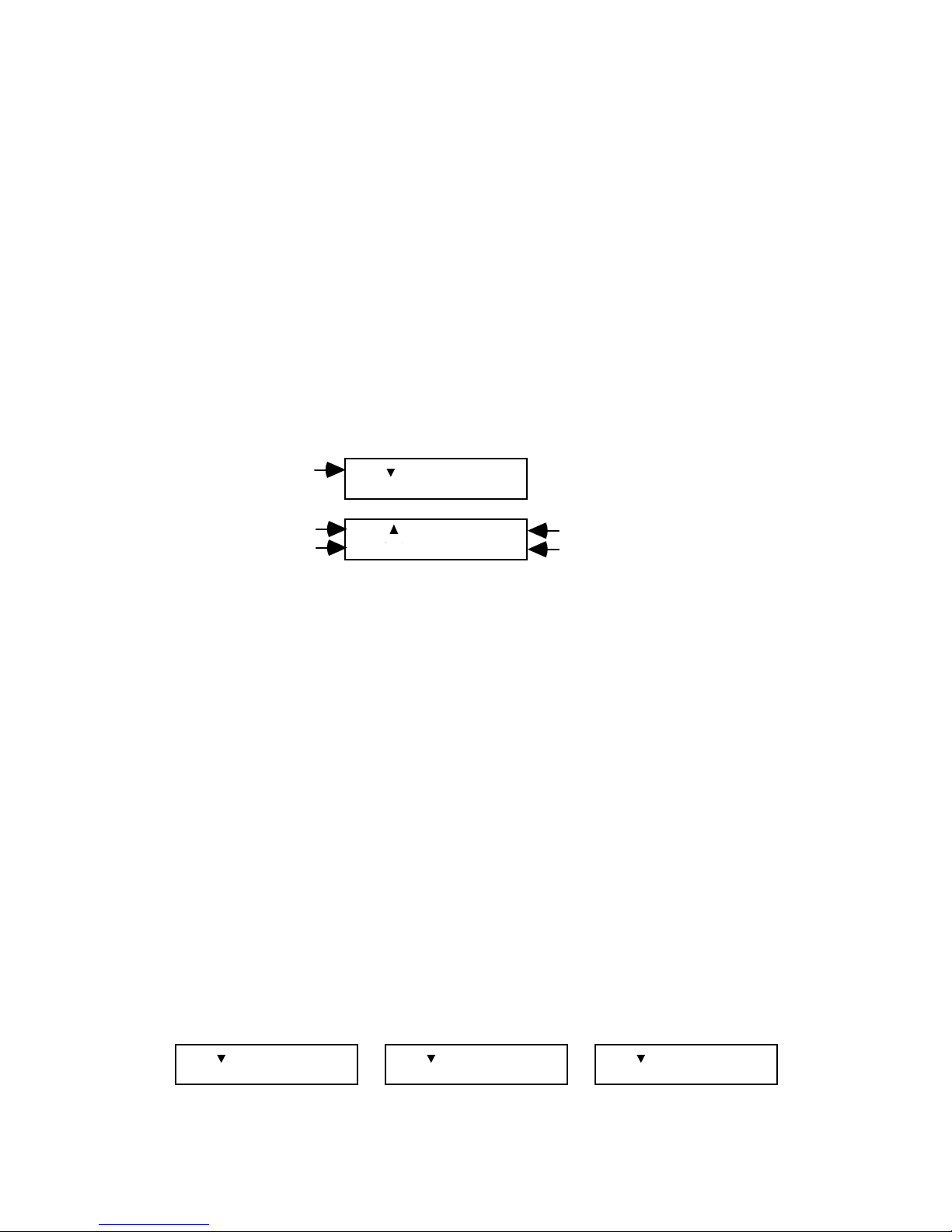
GPI Events
A
A
A
Typically, a GPI (general-purpose interface) Event is used to send a trigger
command to a titler or character generator. The titler will then play a screen of
titles over your video footage before it is sent to the recorder.
Your titler, if you have one, should be connected to the GPI-T port on the back
panel of Edit Suite. If you do not have a mixer or switcher, you can add a second
titler or GPI device to the GPI-M port. If you do this, make sure you change your
GPI-M choice in the CONFIG menu to GPI.
GPI Events are modifiers of your Scene and Source Events. As such, the event
number for a GPI Event is the same as the Scene or Source Event it modifies, as
shown below. If you change the event number for the Scene or Source Event, the
GPI Event number is changed automatically.
Event Number
Event Number
GPI Port (T or M)
001 IN 00:05:20.00
A OUT 00:05:35.00
001 FIXED
GPI-T 00:05:25.00
Fixed or Relative IN/OUT
Fixed Time or Offset Amount
Notice the down arrow on the Scene Event and the up arrow on the GPI Event.
The arrows are called grouping arrows and indicate that there are events (in this
case the GPI Event) related to the Scene Event. Events that are grouped are called
a logical event group.
If there were additional modifier events following the GPI Event, the GPI Event
would have both an up and a down grouping arrow and the subsequent event
would have an up arrow.
How Many GPI Events per Scene or Source
You can have up to 10 GPI Events associated with a single scene or Source Event.
Edit Suite will not prevent you from adding more than 10 GPI Events; however,
when it previews or records your production only the first 10 will be processed.
Fixed, Relative In, Relative Out
GPI Events can be sent at a fixed time code, at a time relative to the start of the
associated scene (Relative In), or at a time relative to the end of the associated
scene (Relative Out).
The following are three sample GPI Events, each using a different time reference,
but each resulting in a GPI Event that would be sent at 00:05:25.00.
001 IN 00:05:20.00
OUT 00:05:35.00
001 IN 00:05:20.00
OUT 00:05:35.00
001 IN 00:05:20.00
OUT 00:05:35.00
Page 55
001 RELATIVE IN
GPI-T +00:00:05.00
001 RELATIVE OUT
GPI-T -00:00:10.00
001 FIXED
GPI-T 00:05:25.00
The Relative IN GPI is sent five seconds after (+00:00:05.00) the IN time of Scene
001 (05:20), so it is sent at 05:25. The Relative Out GPI is sent 10 seconds before (00:00:10.00) the OUT time of Scene 001 (05:35), so it is sent at 05:25.
If the IN time for Scene 001 is changed, the Fixed and Relative Out GPIs are not
affected, but the Relative In GPI will move with the scene's IN time. For example,
if Scene 001's IN time is changed to 05:18.00—two seconds earlier than the
original IN time—the Relative In GPI would now be sent at 05:23.00.
If the OUT time for Scene 001 is changed, the Relative Out GPI Event is affected.
For example, if the OUT time is changed to 05:40.00, the Relative Out GPI would
be sent at 05:30.00.
The Fixed GPI Event will always be sent at the time specified—as long as that
time is somewhere between the IN and OUT times for the scene. If it is outside
the times for the Scene or Source Event, it will be ignored.
GPI Precautions
GPI Events should not be sent earlier than the IN time or later than the OUT time
of the scene to which they are related.
GPI Events are usually used to send a trigger command to a titler or character
generator. Typically, the titles can be timed to remain on the screen for just a few
moments or for several seconds. If the title is still playing when Edit Suite pauses
the record deck at the end of the scene, the remainder of the title will not be
recorded.
For example, if you send a GPI Event five seconds before the OUT time for a
scene, but the title that starts playing stays on the screen for 10 seconds, only the
first five seconds of the title will be recorded.
If you have a mixer or switcher and use an A/B Roll between two sources, the
record VCR will not normally be paused until the OUT time for the "B" source is
reached. Because of this, your titles can be started near the OUT time for scene
"A," be recorded over the A/B Roll, and continue while the "B" source is playing.
Note, however, that if you do an A/B/A Roll or an A/B/C Roll, Edit Suite will
pause the recorder after the first transition in order to position the VCRs for the
second transition. In this case, the titles must be finished at about the same time
the first transition completes or they will continue to play while the record VCR
is paused. See Match Frame Edits in the MX1 Events section of this chapter for
more information about when the VCRs will pause.
Ways to Create a GPI Event
There are two ways to create a GPI Event:
Page 56
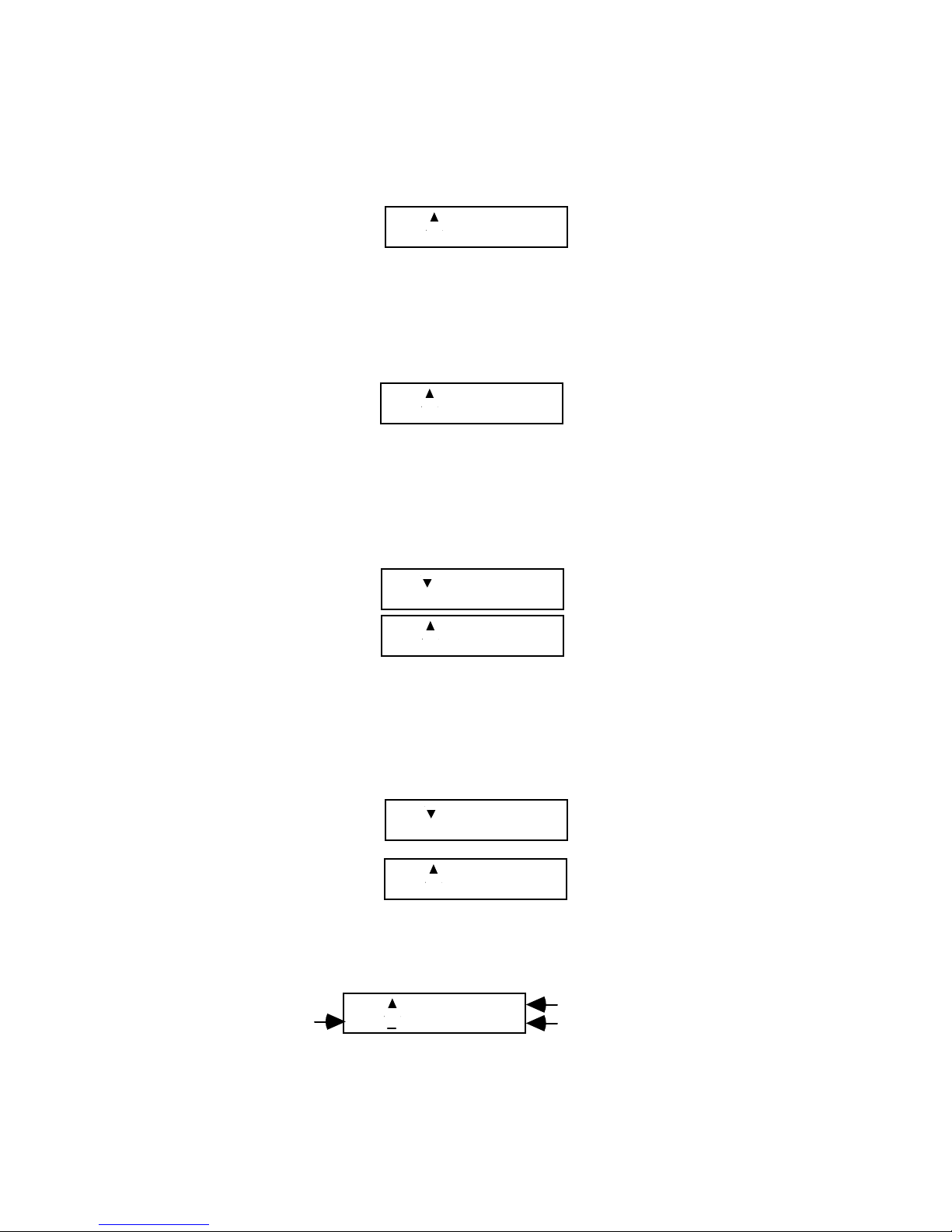
1. The NEW Menu
• Display the NEW menu, select GPI, then press [OK]. Edit Suite will create
an empty GPI Event.
001 FIXED
GPI-T : : .
2. The GPI-T Key
(or the GPI-M Key if the GPI-M port is configured for a GPI device)
• Press GPI-T. A Fixed GPI Event is created with the time code filled in. The
time is the position of the current source when GPI-T was pressed.
001 FIXED
GPI-T 00:05:15.00
If the current source is different from the source for the active scene, a new
Scene Event for the current source is also created. For example, the
following Scene Event has a source of VCR Port A. If this scene is
displayed in the LCD when you press GPI-T and VCR A is the current
VCR, the GPI Event is the only event created.
001 IN 00:05:20.00
A OUT 00:05:35.00
001 FIXED
GPI-T 00:05:25.00
If, however, VCR B is the current source, both a Scene Event for VCR B
and the GPI Event will be created when you press GPI-T. The time in the
GPI-T event will be the time that was current on VCR B when the GPI-T
key was pressed. You will have to mark the IN and OUT times for the
Scene Event.
002 IN 00:00:00.00
B OUT : : .
002 FIXED
GPI-T 00:05:15.00
Changing the GPI Fields
To change the GPI fields:
GPI Port (T or M)
001 FIXED
GPI-T 00:05:25.00
Fixed or Relative IN/OUT
Fixed Time or Offset Amount
• Move the cursor to the GPI-T/M field. Press [CHG] to change between
GPI-M and GPI-T.
Page 57

• Move the cursor to the FIXED field. Press [CHG] to cycle through the
three choices: Fixed, Relative In, and Relative Out.
• Move the cursor to the TIME/OFFSET field. If you selected FIXED, press
[CHG], then enter the time code for the event. If you selected RELATIVE
IN or RELATIVE OUT, press [CHG], then enter the offset amount from
the IN or OUT time of the related Scene or Source Event.
NOTE: If you selected RELATIVE IN or RELATIVE OUT, a sign field (±)
precedes the offset. In most cases, you will use a (+) for a Relative In; in all
cases you should use a (-) for a Relative Out.
Tuning GPI Events
If your GPI Events always start a little earlier or later than where you marked
them, add an offset value to the GPI configuration parameter. The offsets are
measured in 1/8 frame increments, so if the events start one frame late, add an
offset of -0008. If they start one second late, add an offset of -0240 (NTSC=8x30)
or -0200 (PAL=8x25).
Page 58
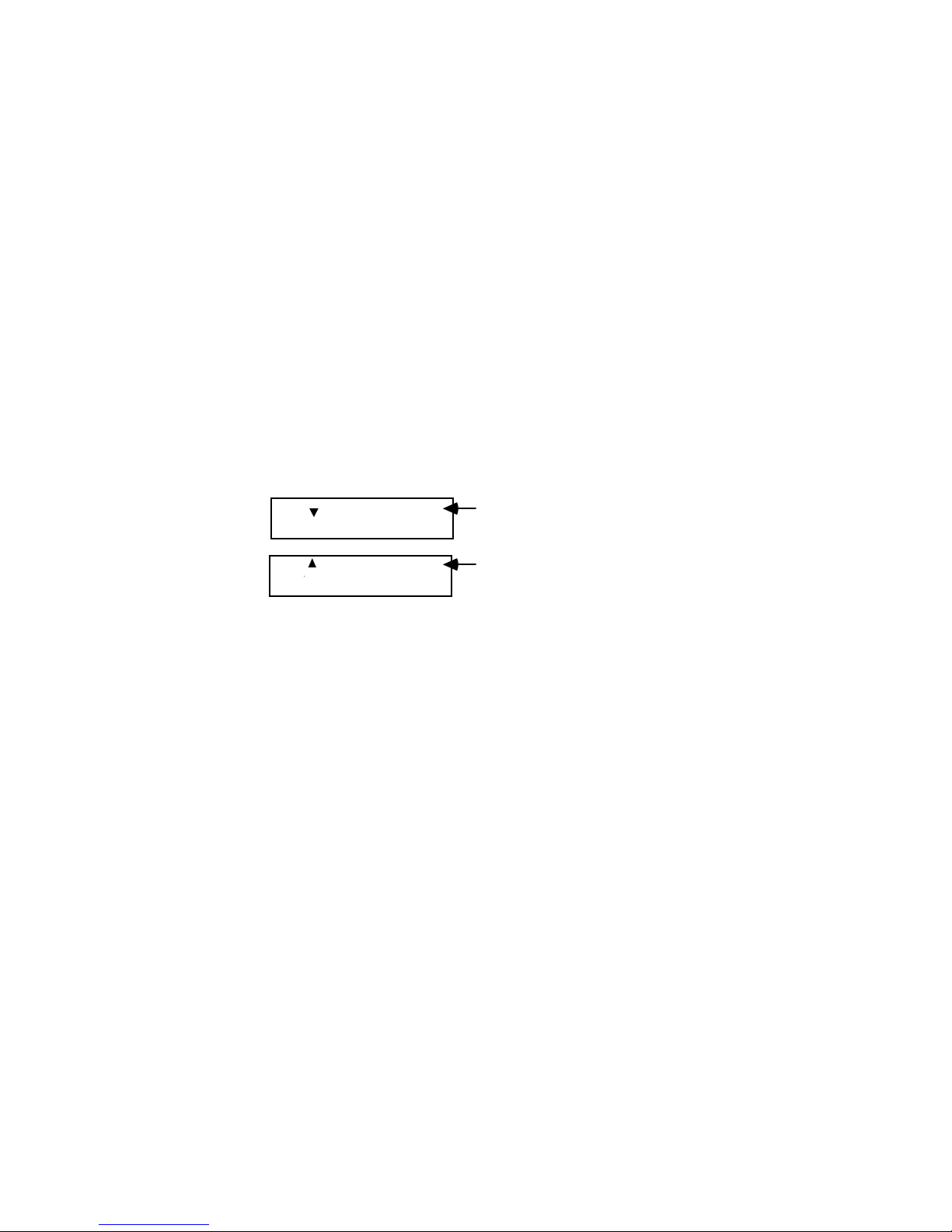
Insert (INS) Events
Insert Events can be used only if the record VCR supports Insert Editing. Check
your record VCR's operating manual to determine if it has this feature.
Insert Editing is the process of replacing some or all of the audio/video on a
previously recorded tape with new audio and/or video. For example, if you
created a 20-minute production but are not happy with the audio track between
the 9th and 10th minute, you can replace that minute of audio without affecting
the rest of the production.
To do this—
• Create a Scene Event to tell Edit Suite which source contains the
replacement audio and where on that tape the audio is located.
• Create an Insert Event to tell Edit Suite where on the record tape the audio
you want to replace is located.
002 IN 00:07:55.00
A OUT 00:08:55.00
002 IN 00:09:00.00
A
INS OUT 00:10:00.00
Source and location of
the audio to be inserted.
Location on the record
tape to insert the audio.
• If they are not already loaded, load the previously recorded tape in the
record VCR and the tape with the new audio into the play VCR.
• Press [SHIFT]+[AUTO REC].
Edit Suite will send commands to the record VCR to position it at the
insert point (or at the insert preroll point for some VCRs), position the
play source at its preroll point, and then tell the record VCR to enter insert
mode.
When both sources are ready, Edit Suite will roll the play source, sending
both the audio and the video from that source to the recorder. Depending
on the type of insert specified and the capabilities of the recorder, the
recorder will record the audio only, the video only, or both the audio and
the video.
Insert Events are always related to a Scene or Source Event, so grouping arrows
are added to both events to show the relationship. The Insert Event is also
assigned the same event number as the Scene or Source Event.
Types of Inserts
In the Insert Event above, the letters INS indicate that the event is an insert. The
A"
"
small
following INS indicates the type of insert to be done. There are three
choices for the type of insert: Audio only (A), Video only (V), and Audio and
Page 59

Video (AV). Which of these you can use depends on the capabilities of the
record VCR. Note: There is no option for splitting Left and Right Audio.
Some VCRs only support video inserts; others support both audio inserts and
video inserts, but not both at the same time, and so on. Read your VCR manuals
carefully to determine the type(s) you can use.
Typically, an audio insert overwrites the PCM audio (CH1/2), a video insert
overwrites the video and the AFM audio, and an audio/video insert overwrites
the video, the AFM audio and the PCM audio. Again, check your Record VCR's
operating manual for specifics.
Insert and Scene Event Times
Although it is best to complete the IN and OUT times for both the Scene Event
and the INS Event, one of the OUT times may be omitted.
• If you omit the OUT time for the INS Event, Edit Suite will use the
duration of the Scene Event to determine the duration for the insert.
• If you omit the OUT time for the Scene Event, Edit Suite will use the INS
event's IN and OUT times to determine the duration of the insert.
• If all four times are specified, but the duration of the Scene Event is
different from the duration of the INS Event, the duration of the INS event
is used. If the Scene Event has a shorter duration, the OUT time for the
Scene Event will be ignored and the source VCR will continue to play
until the insert is complete.
Setup and Precautions
If possible, use VCRs that support time code to do your inserts. This will provide
the best accuracy for locating the insert point and the audio/video to be inserted.
If time code is not available, rewind both the play and record VCRs before
marking the insert points, then verify and adjust the points by using the [GO
TO]+[IN] and [GO TO]+[OUT] functions.
Before you can do an insert, you must set the INS parameter for VCRR (in the
CONFIG Menu) to 1. This indicates to Edit Suite that the record VCR is capable
of doing insert edits. If this is not done, during a preview or auto-record, Edit
Suite will beep twice and display Error Message 23: Insert not available when the
INS Event is encountered. The preview or auto-record will be halted at that time.
Respond to the error message by pressing [OK], then make the necessary change.
If the inserts start or end a little early or late, adjust the InsIN and InsOUT offset
parameters in the Configuration Menu for VCRR. The values are in 1/8 frame
increments: a value of -0008 for the InsIN parameter starts the inserts one frame
earlier; a value of -0240 (NTSC) or -0200 (PAL) starts the inserts one second
earlier.
Page 60
If the InsIN offset is greater than one or two seconds, you will need to increase
the PREROLL time for the Scene Event's play
VCR by a corresponding amount.
The best example of this is a record VCR that uses PANA protocol. Typically, a
Panasonic 5-pin VCR advises Edit Suite that it is in insert mode (and it turns on
its insert indicator) almost seven seconds before it actually begins recording the
insert. During this time there is no counter or tape movement.
You must adjust for this "waiting" time by changing both the InsIN offset for the
record VCR and the PREROLL value for the source VCR/camcorder. For PANA
record VCRs, then, start with an InsIN offset value of -1608 (NTSC) or -1340
(PAL), and increase the PREROLL value for the play VCR from 5 to 12 seconds.
For other protocols, start with the InsIN default value of 0000 and leave the
preroll value for the source VCR set to five seconds.
Ways to Create an Insert Event
There are three ways to create an Insert Event:
1. The NEW Menu
• Display the NEW menu, select INS, then press [OK]. Edit Suite will create
an Insert Event with a default insert type of AV, and with empty IN and
OUT times.
002 IN : : .
A
INS OUT : : .
V
2. The INSERT Key
• Press INSERT. An Insert Event is created with AV as the insert type and
with the IN time set to the current time from the Record VCR. The Record
VCR is also selected as the current VCR so you can use the transport keys
and the jog/shuttle to locate the IN and OUT times for the insert. Press
[IN] to add/change the IN location; press OUT to add/change the OUT
location.
3. The R Key plus IN or OUT
• Press R to select the record VCR.
• Use the transport keys to position the recorder to the IN or OUT point for
the insert.
• Press [IN] or [OUT] to create the INS Event with the IN or OUT time filled
in, depending on which key was pressed.
Page 61

Changing the INS Field Values
To change the INS field values:
002 IN 00:09:00.00
A
INS OUT 00:10:00.00
V
• Move to the INS type field and press [CHG] repeatedly to cycle between
the three choices: AV for both audio and video, A for audio only, V for
video only.
• Use the IN/OUT keys (as described above) to update the IN and OUT
times, or move to the field, press [CHG] to activate the numeric keys, then
either type the value, or use the jog/shuttle to increment or decrement the
value and press [OK].
Page 62
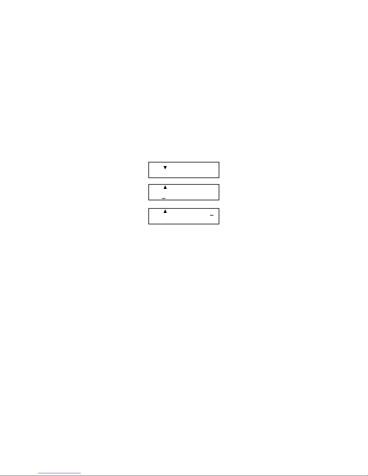
Split Insert (SPLT) Events
Split Insert Events are modifiers of Insert Events and can be used only if your
record VCR supports splitting of the audio and video inputs during Insert
Editing. Check your VCR manual to determine if your VCR can do this.
If you have not already done so, read the previous section about Insert Events.
There are two choices for Split Inserts: Video Delay and Audio Delay. If you
select Video Delay, an Audio Insert will begin at the location specified in the INS
Event and, after the delay specified in the SPLT Event, both the audio and the
video will be inserted. Typically, the delay is only a few seconds.
002 IN 00:07:55.12
A OUT 00:08:55.12
002 IN 00:09:00.00
A
INS OUT 00:10:00.00
V
002 VIDEO DELAY
SPLT 00:00:03.00
Setup and Precautions
A Split Event will not be processed by Edit Suite unless it immediately follows an
Insert Event.
If a Split Insert is to be done, the INS type must be AV.
Before you can do a Split Insert, you must set both the INS and the SPLT
parameters for VCRR (in the CONFIG menu) to 1. In combination, these indicate
to Edit Suite that your record VCR is capable of doing Split Insert edits. If you do
not do this, during a preview or auto record, Edit Suite will beep twice and
display Error Message 24: Split not available when the SPLT event is encountered.
The preview or auto record will be halted at that time. Respond to the error
message by pressing [OK], then make the appropriate changes.
If the split starts or ends a little early or late, you can adjust the SPLT offset
parameter in the Configuration Menu for VCRR. The value is in 1/8 frame
increments, so use a value of -0008 for the SPLT parameter to start your split one
frame earlier, or a value of -0240 (NTSC) or -0200 (PAL) to start your split one
second earlier.
Page 63
Ways to Create a Split Insert Event
There are two ways to create a Split Insert Event:
1. The NEW Menu
• Display the NEW menu, select SPLT, then press [OK]. Edit Suite will
create a SPLT Event with a split type of video delay and a blank duration.
002 VIDEO DELAY
SPLT : : .
2. The SPLIT Key
• Press [SHIFT]+[SPLIT]. If the active event (the event displayed in the
LCD) is an Insert Event, a SPLT Event is created. If the active event is not
an Insert Event, Edit Suite will beep twice and ignore the command.
Changing the SPLT Field Values
To change the SPLT field values:
002 VIDEO DELAY
SPLT 00:00:03.00
• Move to the Delay Type field and press [CHG] to cycle between the two
choices: VIDEO DELAY and AUDIO DELAY. If you want the audio to
start first, select VIDEO DELAY.
• Move to the time code field, press [CHG] to activate the numeric keys,
then enter the amount of delay.
Page 64

Stop Events
STOP Events are used to separate one production from another or to pause a
production to allow you to change tapes, hookups, etc.
TOTAL RT
STOP 00:15:24.00
The STOP Event shows the total running time for your production from the start
of your first Scene or Source Event to the STOP Event or—if you have more than
one STOP Event—from the previous STOP Event to the next STOP Event. The
time is in the format hours:minutes:seconds.frames.
During a Preview or Auto Record, when Edit Suite encounters a STOP Event, it
pauses the preview/record operation and beeps three times. To resume the
operation, use the up/down arrow keys to display the next Scene or Source
Event you want to preview/record, then press [PREVIEW] or [SHIFT]+[AUTO
REC] again. Edit Suite will resume the preview/record and continue until it
reaches the next STOP Event or the last event in your list.
One common use of STOP Events is to separate entire productions. Edit Suite can
hold 250 events, which for many users is enough for several small productions.
The STOP Event will give you the total running time for each of your
productions, and it provides you with an easy method of moving quickly from
production to production. The key combination [GO TO]+[SHIFT]+[up/down
arrow] moves up or down in your list of events from one STOP Event to the next
or to the top/bottom of the EDL if no more STOP Events are encountered.
Another common use of Stop Events is to bracket a series of scenes that you want
to fine-tune. This way you can preview and test-record a small part of your
production rather than the entire production.
A third use for customers who do not have a mixer or switcher is to add a STOP
Event wherever you need to change source tapes.
Ways to Create a STOP Event
There is only one way to create a STOP Event:
• display the NEW menu
• move the cursor to S
TOP
• press [OK].
Page 65

Chapter 6 • Managing The Edit Decision
From anywhere in the EDL,
press [GO TO]+[up arrow] ...
or press [GO TO]+[down arrow].
List
The Edit Decision List (EDL) is the collection of events you create with Edit Suite. Chapter 5 provides
descriptions and instructions for creating each type of event used with Edit Suite. This chapter describes
functions and key combinations that will help you manage the EDL. Included are procedures for–
• Moving up and down through the EDL
• Moving events from one location to another
• Creating copies of events
• Deleting some or all events
• Renumbering all events
To gain a working understanding of the procedures in this chapter, we suggest that you create a small
EDL similar to the one shown below, then practice each procedure as you read through the chapter. This
will make it easier for you to recall the procedures and key sequences when you need to use them for
your own productions.
Moving Up and Down Through the EDL
In Step 10 of the Getting Started you created the first two events in your EDL. With only two events, it
was easy to move from one event to the next by pressing the up and down arrow keys.
But a full EDL can contain up to 250 events. How can you move quickly to the top or bottom of the
EDL? Or from one Scene or Source Event to the next? Or from one Stop Event to the next? This section
describes the key combinations to do all of these, as well as providing a procedure to display a specific
event.
To move to the top or bottom of the EDL–
Page 66
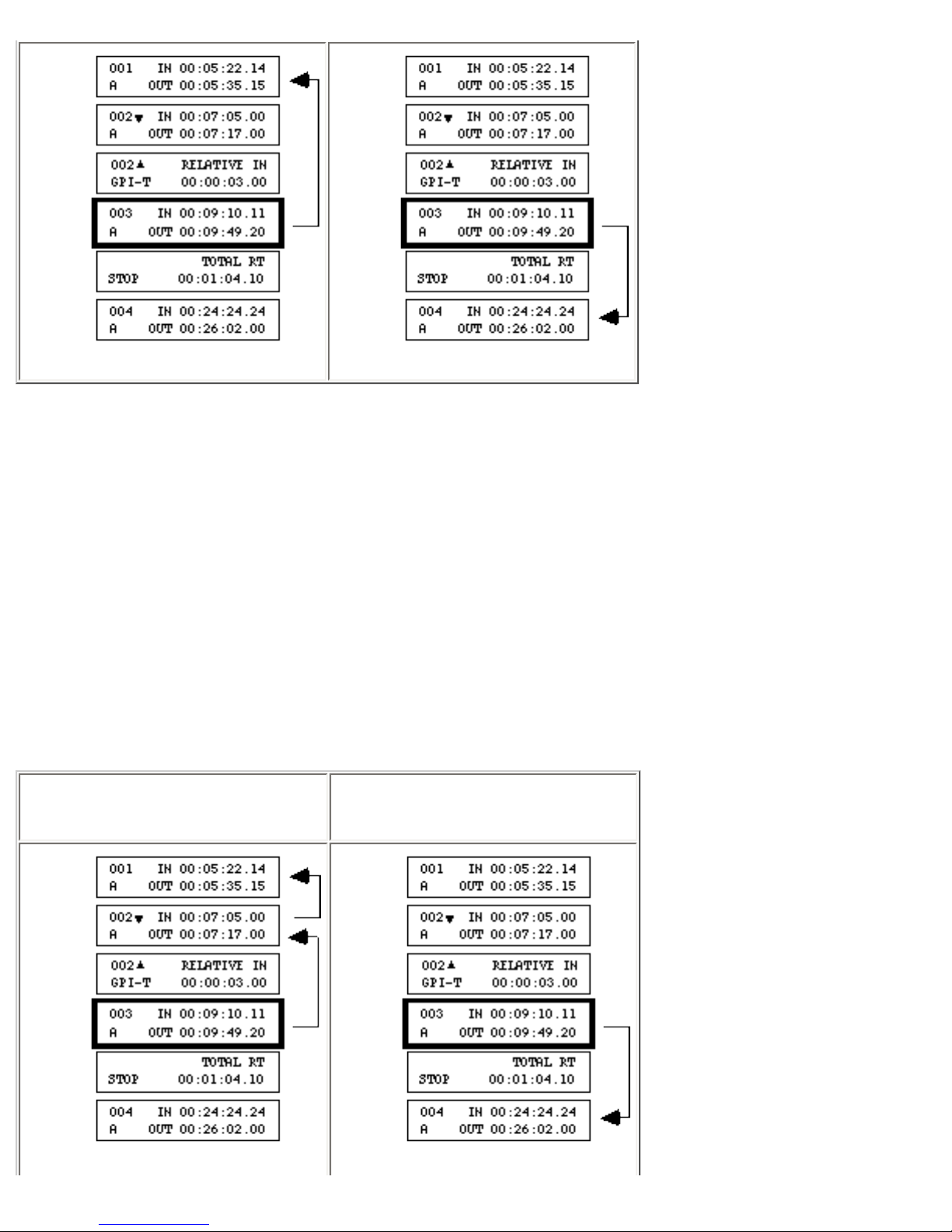
In the preceding example, event 003 is the active event (the event displayed in the LCD) when the GO
From anywhere in the EDL,
press [SHIFT]+[up arrow] ...
or press [SHIFT]+[down arrow].
TO+up/down arrow keys are pressed. The arrows indicate which event will display next.
You often move to the top of the EDL before doing a preview or auto-record so that all the events in the
EDL are previewed/recorded.
You often move to the bottom of the EDL before adding new scenes. This way the new scenes are added
after the existing scenes. Otherwise, new scenes are added after the active event.
To display the previous or next Scene or Source Event–
Page 67
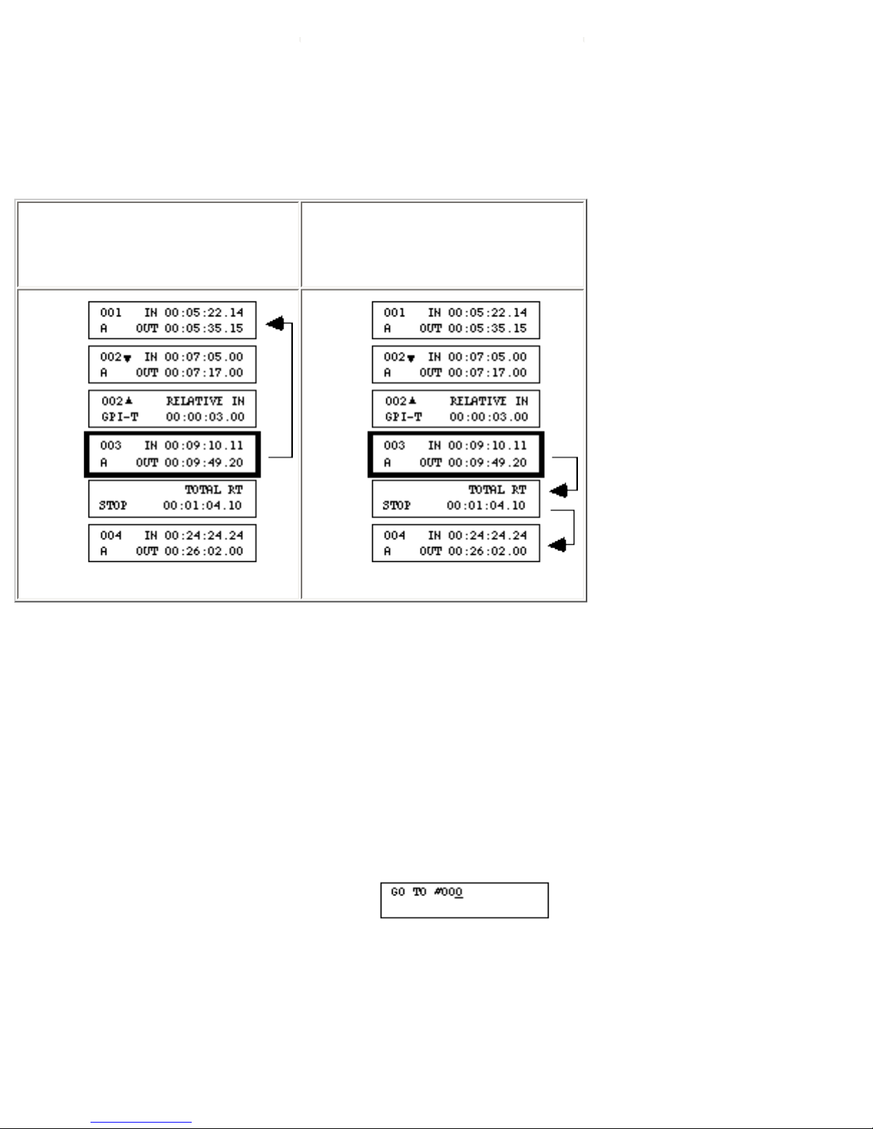
Each press of [SHIFT]+[up/down arrow] moves up or down to the previous/next Scene or Source Event.
All GPI, MX1, MIXER, INS, SPLT, and STOP events are skipped.
From anywhere in the EDL,
press [GO TO]+[SHIFT]+[up
arrow] ...
or press [GO TO]+[SHIFT]+
[down arrow].
To display the previous or next Stop Event–
If there are no more Stop Events between the current event and the top/bottom of the EDL, the top/
bottom event displays.
If you use Stop Events to separate your productions, the above key sequence provides an easy method of
moving from one production to the next.
To display a specific event–
• Press [GO TO]+[OK] to display the Go To screen.
• Press [CHG] to activate the numeric keys.
• Type the event number (leading zeroes do not need to be entered), then press [OK].
- If the event number exists in the EDL, that event is displayed.
Page 68
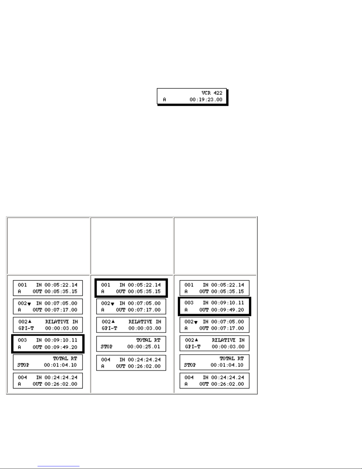
- If the event number does not exist in the EDL,
Error 22: Invalid ED#, displays. Press
1. Display the
event to be
moved and
press [CUT].
2. Display the
new location
for the "cut"
event.
3. Press
[PASTE].
[OK] to clear the message.
- If the live tile (below) displays after you run this procedure, you were controlling a VCR
when [GO TO]+[OK] was pressed. Press [OK] to display the event.
Moving Events
After previewing your production, you may find it necessary to move some events from one location to
another. This section describes procedures for moving an individual event or a group of events.
To Move an Event From one Location to Another–
In the above example, Scene Event 003 is moved from its original location to a new location following
event 001.
When [CUT] is pressed (Step 1), the event is deleted from the EDL and placed into a temporary storage
Page 69
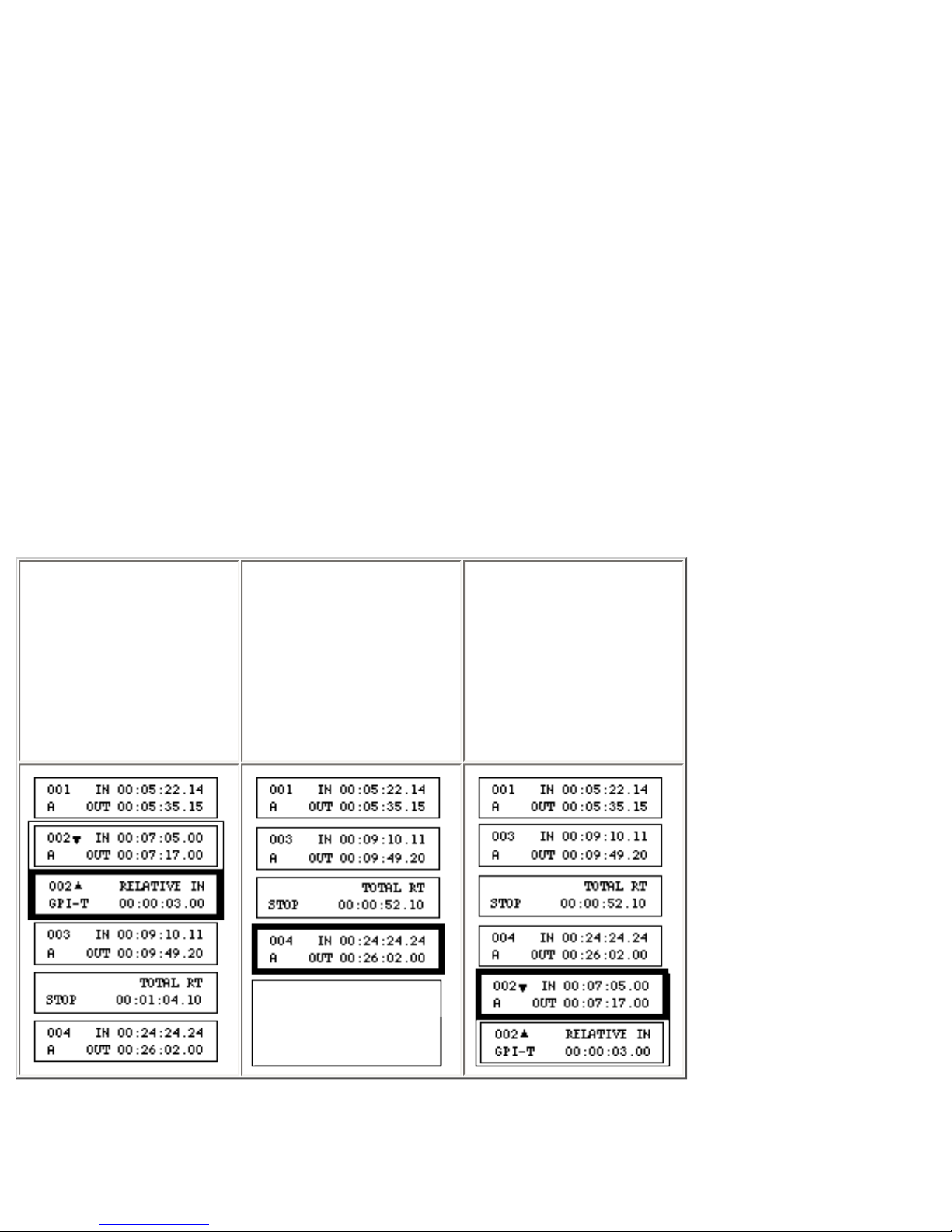
location, called the
paste buffer. It remains in the paste buffer until [PASTE], [CUT] or [COPY] is
1. Display any
event in the
group to be
moved and
press [SHIFT]
+[CUT].
2. Display the
new location
for the "cut"
group of events.
3. Press
[PASTE].
pressed.
When [PASTE] is pressed (Step 3), the event is pasted after the active event. If [SHIFT]+[PASTE] is
pressed instead of [PASTE], the event is pasted before the active event.
Caution: Each time [CUT] or [COPY] is pressed, any events already in the paste buffer are deleted
before the new events are added. If you inadvertently press [CUT] a second time before pressing
[PASTE], the event you wanted to move will be deleted.
Notice the order of the events in the third column. Event 003 retained its old event number instead of
causing the entire list to be renumbered. This way, you can keep track of events by their original event
numbers no matter where they are located in the EDL. If you want to renumber the events so that the
event number matches the event's position in the EDL, press [GO TO]+[SHIFT]+[CHG].
To Move a Group of Events From one Location to Another–
In the above example, the group of events that includes scene 002 is moved from its original
location to a new location following event 004.
Page 70
When [SHIFT]+[CUT] is pressed (Step 1), all the events in the group are deleted from the EDL
and placed into a temporary storage location, called the paste buffer. They remain in the paste
1. Display the
event to be
copied and
press [COPY].
2. Display the
new location
for the copied
event.
3. Press
[PASTE].
buffer until [PASTE], [CUT] or [COPY] is pressed.
When [PASTE] is pressed (Step 3), the entire group of events is pasted after the active event. If
[SHIFT]+[PASTE] is pressed instead of [PASTE], the group is pasted before the active event.
Caution: Each time [CUT] or [COPY] is pressed, any events already in the paste buffer are
deleted before the new events are added. If you inadvertently press [SHIFT]+[CUT] a second
time before pressing [PASTE], the group of events you wanted to move will be deleted.
Notice the order of the events in the third column. Event 002 retained its old event number
instead of causing the entire list to be renumbered. This way, you can keep track of events by
their original event numbers no matter where they are located in the EDL. If you want to
renumber the events so that the event number matches the event's position in the EDL, press [GO
TO]+[SHIFT]+[CHG].
Copying Events
There may be occasions when you want to use the same event in more than one location in your
production. This section provides procedures for copying individual events and groups of events and
pasting the copies in a different location in your EDL.
To Make a Copy of an Event–
Page 71
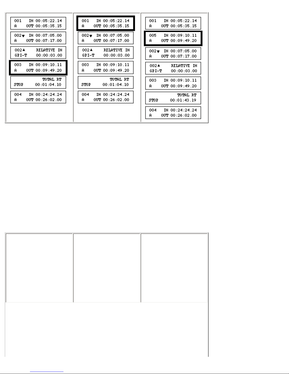
In the above example, a copy of event 003 is placed after event 001. The copy is assigned the next
1. Display any
event in the
group of events
to be copied
and press
[SHIFT]
+[COPY].
2. Display the
new location
for the copied
group of events.
3. Press
[PASTE].
available event number–005 in this case.
To place the new event before the active event, instead of pressing [PASTE], press [SHIFT]+[PASTE].
After [PASTE] or [SHIFT]+[PASTE] is pressed (Step 3), the paste buffer is empty. To make another
copy of the event, repeat the procedure.
To Make a Copy of a Group of Events–
Page 72
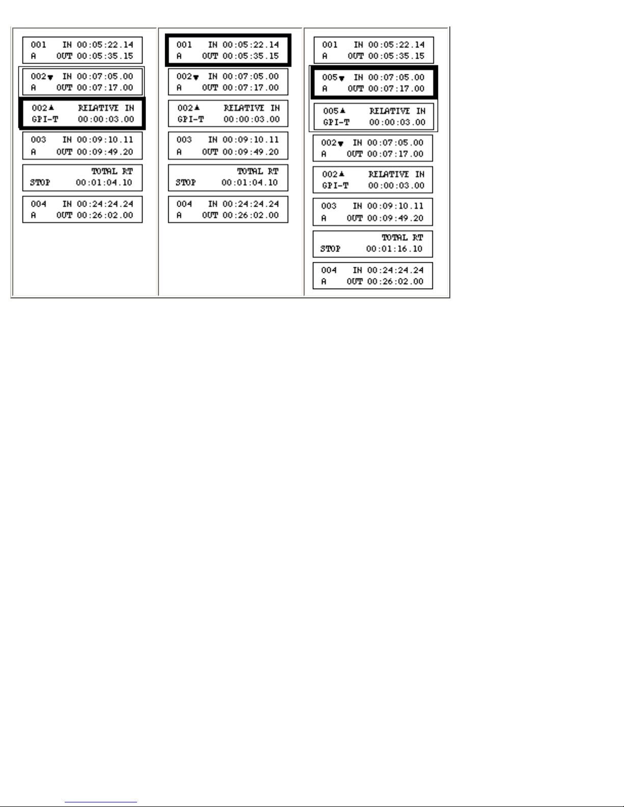
In the above example, a copy of the group of events that includes event 002 is being placed after event
001. The group is assigned the next available event number(s)–005 in this case.
To place the new group before the active event, instead of pressing [PASTE], press [SHIFT]+[PASTE].
After [PASTE] or [SHIFT]+[PASTE] is pressed (Step 3), the paste buffer is empty. To make another
copy of the group, repeat the procedure.
Deleting Events and Event Contents
This section describes the procedure for deleting the contents of an event, as well as procedures for
deleting–
• a single event
• a group of events
• all Stop Events in the EDL
• all GPI-T or GPI-M events in a group
Page 73
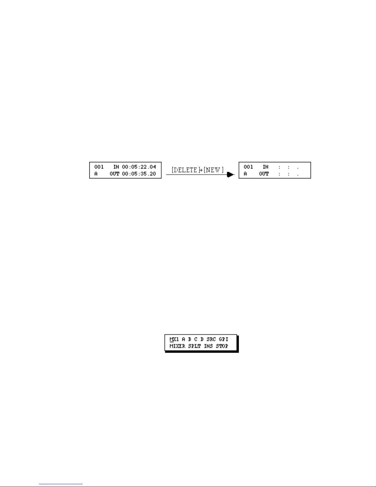
• all GPI-T or GPI-M events in the EDL
• all events in the EDL
To Delete the Contents of an Event–
1. Display the event.
2. Press [DELETE]+[NEW].
The event remains, but the contents of the event are deleted and the default values–if
any–are added. For example, in a scene event, the IN and OUT times are deleted.
To Delete an Event–
1. Display the event.
2. Press [DELETE]+[CUT] or press [CUT].
Pressing [DELETE]+[CUT] deletes the event without putting a copy of the event in the
paste buffer. Pressing [CUT] deletes the event but puts a copy in the paste buffer so the
event can be pasted to a new location. (See Moving Events earlier in this chapter.)
Note: If you delete the last remaining event in the EDL, Error Message 13, EDL empty,
displays. Clear the message by pressing [OK]. The NEW menu (below) will display.
To create a new Scene or Source Event, use the NEW Menu, the VCR Selector keys
([SHIFT]+[A, B, C or D]) or, if you have an MX-1, the COLOR key ([SHIFT]
+[COLOR]) .
To Delete a Group of Events–
1. Display any event in the group of events to be deleted.
2. Press [SHIFT]+[DELETE]+[CUT] or press [SHIFT]+[CUT].
Page 74
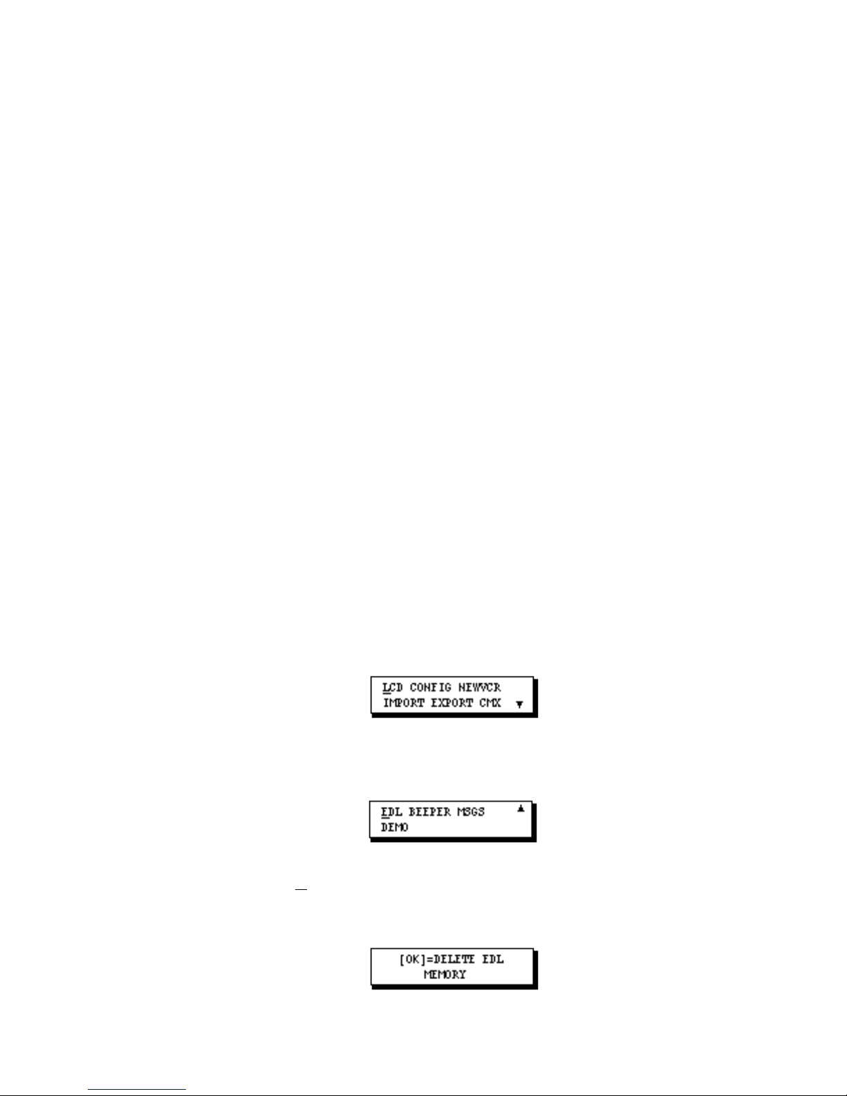
Pressing [SHIFT]+[DELETE]+[CUT] deletes the group of events without putting a copy
of the events in the paste buffer. Pressing [SHIFT]+[CUT] deletes the group of events but
puts a copy in the paste buffer so the events can be pasted to a new location. (See Moving
Events earlier in this chapter.)
To Delete all STOP Events in the EDL–
• Press [SHIFT]+[DELETE]+[ALL STOP].
To Delete all GPI-T or GPI-M Events in a Group of Events–
1. Display any event in the group.
2. Press [DELETE]+[GPI-T] or [DELETE]+[GPI-M].
To Delete all GPI-T or GPI-M Events in the EDL–
1. Display any event in the group.
2. Press [SHIFT]+[DELETE]+[GPI-T] or [SHIFT]+[DELETE]+[GPI-M].
To Delete all Events in the EDL–
1. Press [SETUP] to display SETUP Menu 1 (of 2).
2. Press [down arrow] twice to display SETUP Menu 2.
3. Move the cursor to EDL (if it is not already selected) and press [OK]. The following
message displays.
4. To delete all events from the EDL, press [OK]. After a few moments, Setup Menu 2
Page 75
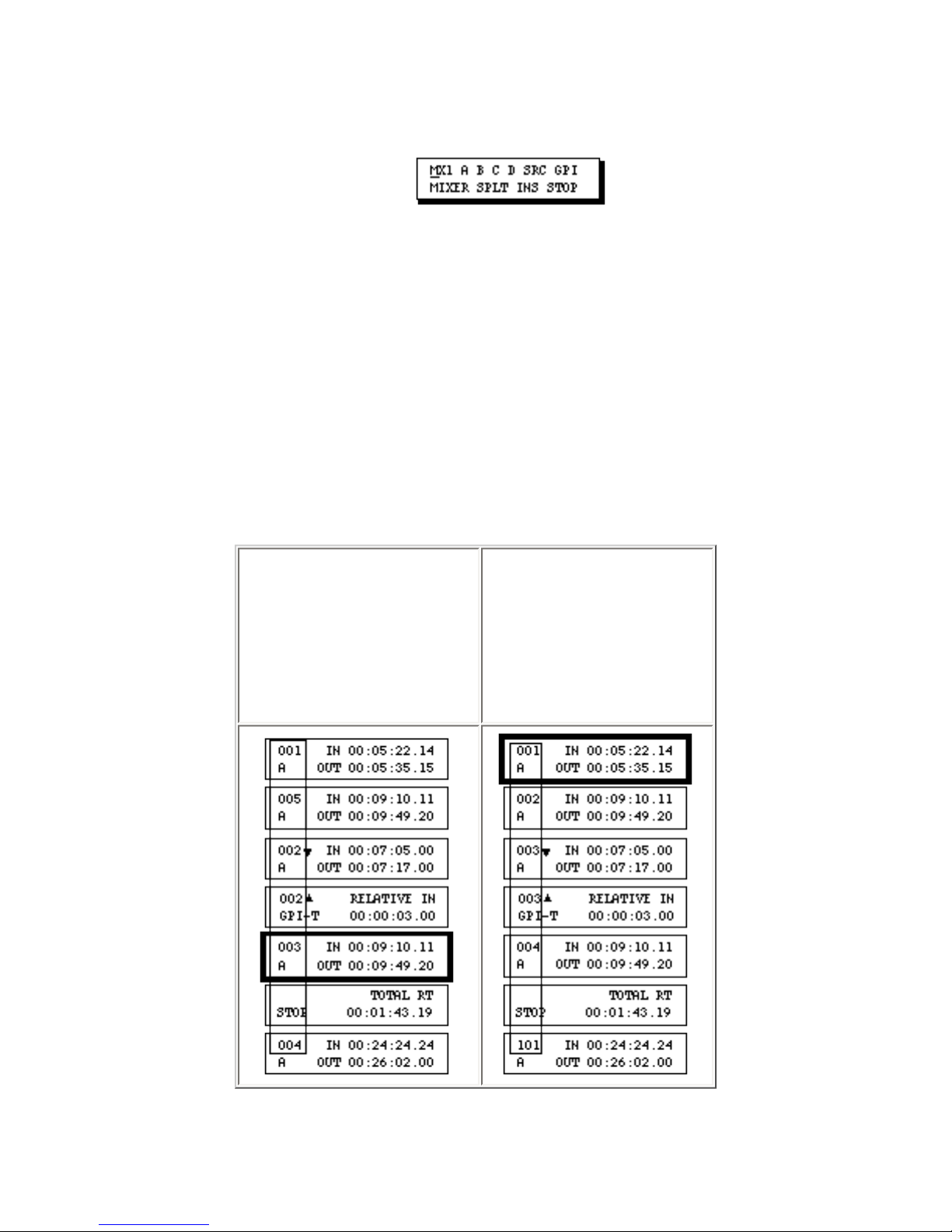
redisplays.
1. From
anywhere in the
EDL, press [GO
TO]+ [SHIFT]
+[CHG].
2. The events are
renumbered in a
numerical
sequence.
Press [SETUP] to leave the Setup Menus and display the New Menu.
NOTE: To cancel the delete function without deleting any events, press [SETUP] to
return to the second Setup menu, then press [SETUP] again to return to the EDL.
Renumbering all Events in the EDL
After deleting, moving and copying events, the event numbers in the EDL will probably be out of a
numerical sequence. Although this poses no problem for Edit Suite, you may want the event numbers to
be in sequential order. To do this–
Events are renumbered beginning with number 001.
Page 76

Only Scene (A, B, C, D) and Source (SRC) Events are assigned unique event numbers. All other events
relate to Scene or Source Events and are assigned the same event number as the scene/source to which
they relate. An example of this is shown with the GPI Event, above.
When a STOP Event is encountered, the hundreds digit is incremented and the tens and units digits are
reset to 01. For example, the first Scene or Source Event after the first STOP Event will be event 101 (as
shown in Step 2, above); the first event after the second STOP Event will be 201, and so on.
If nine or more STOP Events are used to separate the EDL events, the hundreds digit is not incremented
after any STOP Event: all scene and source events will be numbered in sequence. For example, if there
were nine or more STOP Events in the above EDL, event 101 would be assigned event number 005.
Page 77
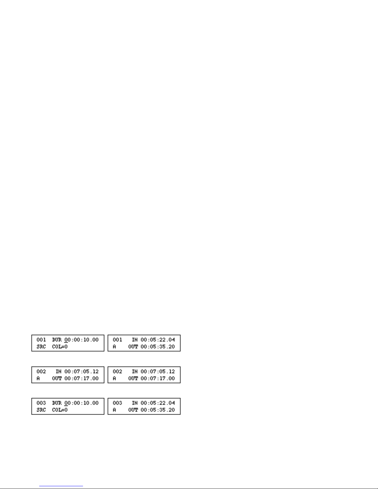
Chapter 7 • Fine Tuning
After you have configured Edit Suite and recorded some scenes, you may find that the recorded scenes
start or end a few frames early or late. If this is the case, use the IN and OUT OFFSET parameters to
fine-tune Edit Suite.
Before Adjusting the Offset Parameters
If you do not have time code (VITC, LTC or RCTC) available, before you begin marking scenes or
adjusting parameters, rewind the videotape and reset the VCR counter to zero. Repeat the rewind and
rezero procedure periodically while you are marking scenes–especially if there has been a lot of backand-forth movement of the videotape. This will minimize the amount of "slippage" that occurs over time
in the VCR's transport.
Use Edit Suite's GO TO - Zero function (select the VCR then press [GO TO]+[0]) to rewind the tapes.
For VCRs with PANA and LANC protocols, this function will also rezero the counter.
Tape speed is also important in deck tuning. The best speed to use for video and audio quality and for
editing accuracy is SP. Be consistent with the speed you select.
Preparation
To begin the fine-tuning procedure, create an EDL with three events.
If you have a Videonics MX-1, make the first event an SRC event with a 10-second duration and
COL=0 (black), make the second event a scene with a duration of approximately 10 seconds, and make
the third event another SRC event with a 10-second duration and COL=0.
If you do not have an MX-1, create three scene events from the same source each with a duration of
Page 78

approximately 10 seconds.
In both cases, the first and the third events are "don't care" events for VCR fine tuning. The IN and OUT
locations for the second event are the important locations. With this in mind, when you select the IN and
OUT points for the second event, select a scene that is easily identifiable, such as a car passing a street
sign or a door slamming shut. If you have a window dub (a tape recorded with a time code readout
displayed on the video), use it.
Play VCRs OUT OFFSET
The first parameter to verify is the OUT OFFSET for each of the play VCRs–A, B, C and D. The OUT
OFFSET is used by Edit Suite to determine when it needs to send a Pause command to the VCR so that
the player pauses at the correct time.
Note: For VCRs whose PROTO= 232 or 422 AND whose TCSRC=INT, this parameter is not used.
These VCRs control their own searches.
To determine if the Out Offset needs to be adjusted–
1. Use the up/down arrow keys to display the second EDL event.
2. Press [GO TO]+[IN] to have Edit Suite search for the IN time for the second event.
3. When the VCR pauses, press [OK] to redisplay the EDL.
4. Determine the direction of error.
- If the VCR paused at the position you marked for the IN time, no adjustments are
necessary. Change the source for the Scene Events to the next source, switch the
videotape to that source, and repeat steps 1-4 for all other play VCRs.
- If the VCR paused before the position for the IN time, the value for the Out Offset is too
large and needs to be decreased.
- If the VCR paused after the position for the IN time, the value for the Out Offset is too
small and needs to be increased.
5. Determine the amount of error.
Error is measured in frames. There are 25 frames per second in a PAL (Europe, Asia,
Middle East, Australia) system and 30 frames per second in an NTSC (US, Canada,
Page 79

Japan) system.
Depending on the type of VCR or camcorder you are using, you can measure the amount
of error accurately by turning the jog knob slowly, watching the monitor carefully, and
counting the number of frames that change. Turn the knob clockwise if Edit Suite paused
too early, or counterclockwise if it paused too late.
If your VCR or camcorder does not have jog capabilities, estimate the number of frames
of error.
If you have a window dub and you know the dub time that equates to the IN time for your
scene, you can calculate the difference in frames.
6. Determine the change to the offset value.
Offsets are measured in 1/8 frame increments. Multiply the amount of error you
determined in Step 5 by eight. (For example, five frames of error times eight is 40.) This
is the amount of change you should make to the play VCR's OUT OFFSET parameter.
7. Add or subtract the value in Step 6 to the current OUT OFFSET value, then repeat this
procedure to verify your changes. If you find that sometimes you are a frame or two early
and sometimes a frame or two late, select the midpoint for the offset.
See Accessing and Changing Offset Parameters at the end of this chapter.
Record VCR (VCRR) IN and OUT OFFSETS
After the Out Offsets for the Play VCRs are adjusted, determine whether the In and Out Offsets for the
Record VCR need to be adjusted. The IN OFFSET determines when the Record command is sent. The
OUT OFFSET determines when the Record Pause command is sent.
To determine if the Record VCR In and Out Offsets need to be adjusted:
1. Insert a blank tape in the Record VCR and rewind the tape.
If PROTO=422 and TCSRC=INT, follow the instructions in your VCR manual to
prestripe your tape, then position the tape approximately one minute from the start.
2. Use the up/down arrow keys to display the first of the three events you created in the
Preparation section.
Page 80

3. If the record VCR uses IR control, put the VCR in Record Pause.
4. Press [SHIFT]+[AUTO REC] to record the three scenes.
5. After the three scenes are recorded, press [R] to select the record VCR. (If the record
VCR uses IR, you will have to control it manually.)
6. Use the jog/shuttle to locate the start of the second scene.
If the scene started earlier than the IN point, the value for VCRR's In Offset is too large. If
it started later than the IN point, the offset is too small. Use the same approach as you
used for the Play VCRs OUT OFFSET to determine the amount of error and the amount
of change to the current offset value. Change the IN OFFSET and continue with Step 7.
See Accessing and Changing Offset Parameters at the end of this chapter.
7. Use the jog/shuttle to locate the end of the second scene.
If the scene ended earlier than the OUT point, the value for VCRR's OUT OFFSET is too
large. If it ended later than the OUT point, the offset is too small. Use the same approach
as you used for the Play VCRs OUT OFFSET to determine the amount of error and the
amount of change to the current offset value. Change the OUT OFFSET.
8. Repeat these steps to verify your changes.
If you do not have an MX-1 or a mixer/switcher, this concludes the fine-tuning procedure. If you have a
Mixer or Switcher, continue with the next section.
Play VCRs IN OFFSET
The Play VCR IN OFFSET is used only during A/B Rolls and is used to determine when the play
command needs to be sent to the "B" Roll VCR in order to start the transition at the correct time. If you
are not using a mixer, you do not need to adjust this parameter.
To determine if the Play VCR IN OFFSET needs to be adjusted:
1. You need two source VCRs, and two more events in the EDL.
The first new event is an MX1 or MIXER Event, and it should be created immediately
following the scene 002 event. Select a transition–like MX-1 transition 6–that will allow
you to judge the midpoint of the transition. Select the speed or duration you use most
Page 81
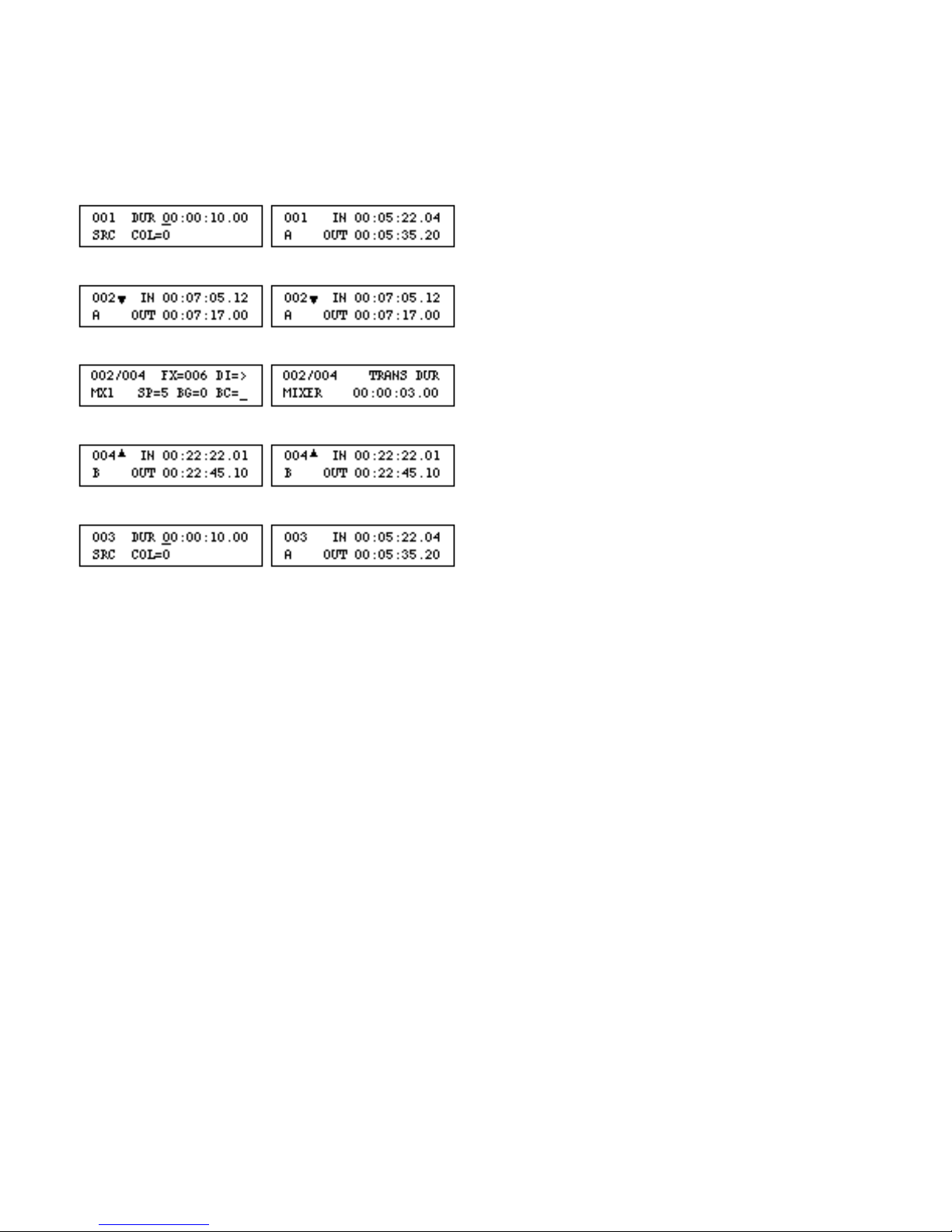
often for your productions.
The second new event is a Scene Event (A, B, C or D), and it should immediately follow
the MX-1 or MIXER event. The new event should be from a different play VCR than
scene 002. The EDL should look similar to one of the EDLs below.
2. Use the up arrow to move to the first event in the EDL.
3. If the Record VCR uses IR control, put the VCR into Record Pause.
4. Press [SHIFT]+[AUTO-REC] to record the scenes.
5. After the scenes are recorded, press [R] to select the record VCR. (If the Record VCR
uses IR, you will have to control that VCR manually.)
6. Check the resulting video on the Record VCR for the midpoint of the transition from A
to B. If the "B" scene started early, the IN OFFSET for the B-Roll VCR is too large; if it
started late, the offset is too small. (Note: The "B" VCR in this case is the second source
in the A/B Roll and not necessarily the VCR attached to the "B" port.)
7. Use the same approach as you used for the Play VCRs OUT OFFSET to determine the
amount of error and the amount of change to the current offset value. Change the IN
OFFSET value.
8. Repeat steps 2 through 7 to verify your changes.
Page 82
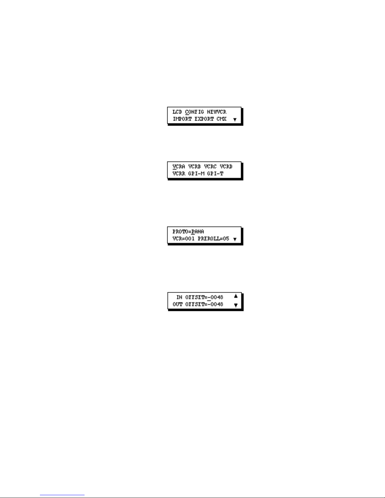
9. Repeat the above procedure for each play VCR that may be the "B" source in an A/B
Roll.
Accessing and Changing Offset Parameters:
1. Press [SETUP] to display Setup Menu 1.
2. Move the cursor to CONFIG and press [OK] to display the Configuration Menu.
3. Move the cursor to the VCR port (VCRA, VCRB, ... ,VCRR) whose offsets you are
ready to adjust and press [OK]. The first parameter screen for that port displays.
4. Press the down arrow key three or four times until the IN/OUT OFFSET screen is
displayed.
5. To change an offset value–
• Move the cursor to the ± Sign field if that value needs to change and press [CHG].
• Move the cursor to the Offset Amount field if that value needs to change, press [CHG] to
activate the numeric keys, then enter the new value for the offset.
• Press [SETUP] to save your changes and return to the Configuration Menu. Press
[SETUP] two more times to return to the EDL.
Page 83
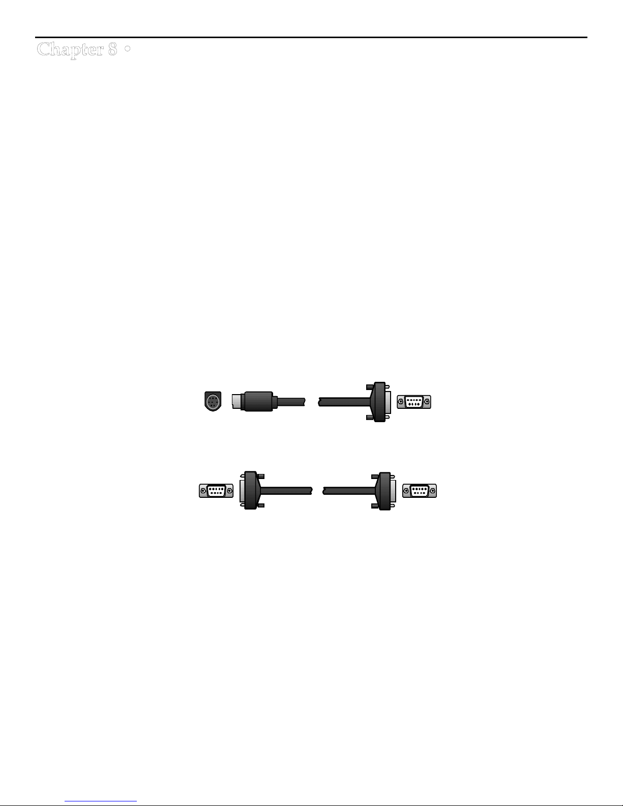
Importing and Exporting
If you have access to a personal computer (PC) and a communications software program, you can use
Edit Suite's IMPORT, EXPORT, and CMX functions to—
• export the EDL and Configuration Parameters to a PC
• import a previously exported EDL and parameters to Edit Suite
• export the EDL, in CMX format, to a PC.
The EXPORT and IMPORT functions are for storage purposes only. You cannot view the file in a
readable format or edit the EDL data.
The CMX export displays in a readable format, but the format is different from the EDL format.
Although this output was designed to make the EDL available to an on-line suite (PC-based editing),
it is used most often to view the EDL information.
Cable
To connect Edit Suite to a PC, you need a serial communications cable. These cables are available at
most computer supply stores. For a Macintosh, the cable is an 8-pin DIN to DB-9. A Videonics
232/422 cable (CBLA-0042-01) may be used.
For most other computers, the cable is a DB-9 to DB-9 or DB-25 to DB-9 serial communications cable.
Before connecting the cable, remove power from the computer and Edit Suite.
Macintosh Modem Port (8-pin DIN) to Edit Suite's Computer (RS-232C) DB-9 Port
PC Serial Comm Port (DB-9 or DB-25) to Edit Suite's Computer (RS-232C) DB-9 Port
Page 84
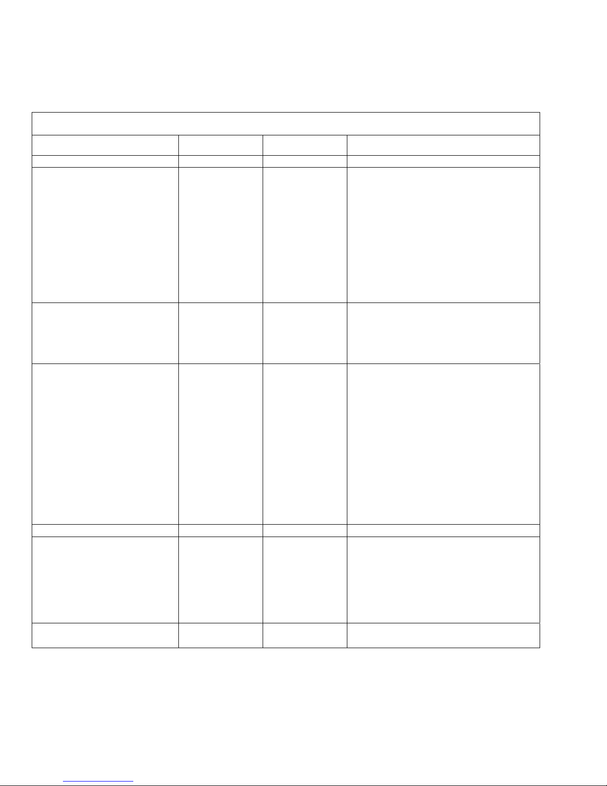
Communication Programs and Settings
Edit Suite can communicate with most communication software programs that support XOn/XOff
Flow Control. The table on the following page identifies three communication programs we have
tested with Edit Suite, and the settings for each. Adapt these settings to your software package.
Communication Programs and Settings
Computer Macintosh PC DOS PC Windows
Communications Program MicroPhone II ProComm Terminal
Communications Menu
Method
Driver
Baud Rate
Data Bits
Parity
Stop Bits
Flow Control
Parity Check
Carrier Detect
Text Transfer
End Outgoing Lines with:
Save Text As:
Wait for Echo
Flow Control
ASCII Transfer
Echo Local
Expand Blank Lines
Pace Characters
Character Pacing
Line Pacing
Down Loading
CR
LF
Up Loading
CR
LF
Terminal Emulation
Terminal Preferences
Line Wrap
Local Echo
Sound
CR->CR/LF
Inbound
Outbound
Transfer/Send Menu
Protocol
Microphone Std.
Standard
19,200
8
None
1
XOn-XOff
CR
Teach Text
None
Press Alt-S,
DEC VT-100 or DEC VT-52
ASCII/Text
Press Alt-P and
select table 12.
19,200
8
None
1
select menu 6.
Yes
Yes
0
23
11
None
None
None
None
Ensure that all settings are correct before you begin communicating with Edit Suite. Test by running
Edit Suite's Export function without saving the data that is sent. You should see 255 lines of 32
characters per line scroll down your PC display. If not, either some of the above values are not set
properly or your modem/communications port is not configured for computer-to-computer
communications. Consult your PC or communication manuals for more information.
19,200
8
None
1
XOn-XOff
(blank)
(blank)
Standard
X
X
X
(blank)
(blank)
Page 85
Export
The Export function is used to save all EDL and Configuration Data to a file on a personal computer.
The file cannot be edited at the PC, and it is not in a readable format. The file can be sent back to Edit
Suite via the Import function.
To do an export, complete the following steps.
# Step Macintosh
MicroPhone II
1. At the PC, start the
communications
program.
2. At the PC, create a file to
save the Edit Suite data.
3. At Edit Suite:
a. Press [SETUP] to
display Setup Menu 1
and move the cursor
to Export.
b. Press [OK] to display
the Export screen.
c. Press [OK] to start the
export
— or —
press [SETUP] to
cancel the export.
4. After the Edit Suite
counter stops counting
and the Setup Menu
redisplays, at the PC,
stop the file capture.
Select Open New
Capture File in the
File Menu.
Select a directory
and file name.
Click SAVE.
While the export is in progress, line numbers
Select Turn Capture
Off in the File
Menu.
PC DOS
ProComm
Press [Page Down]
to display the
Download
Protocol menu.
Select Protocol 7
(ASCII).
Assign a file name
and press return.
LCD CONFIG NEWVCR
IMPORT EXPORT CMX
[OK]=BEGIN EXPORT
[OK]=BEGIN EXPORT
24_
between 00 and FF sequence on the display.
(No action
required.)
Select Receive Text File... in the
Transfers Menu.
Select a directory and file name.
Click OK.
Select Stop in the Transfers Menu.
PC Windows
Terminal
Page 86
Import
The import function is used to restore a previously exported Edit Suite file.
IMPORTANT: If an import is done, all EDL and configuration data currently stored in Edit Suite will
be replaced by the imported data. All work-in-progress will be lost.
Before attempting an import, ensure that all communication settings are correct. If the connections
are not correct and the import fails, Edit Suite displays an NVRAM INIT message indicating that all
EDL and configuration data has been deleted and the unit has been reset to factory conditions.
To do an import, complete the following steps.
# Step Macintosh
MicroPhone II
1. At the PC, start the
communications program.
2. At the PC, locate and
select the previously
exported EDL file that
you want to send to Edit
Suite
... BUT DO NOT START
SENDING THE FILE YET.
3. At Edit Suite:
a. Press [SETUP] to
display Setup Menu 1
and move the cursor to
Import.
b. Press [OK] to display
the Import screen.
c. Press [OK] to prepare
Edit Suite for the
import and to start a
10-second time-out
counter.
— or —
press [SETUP] to
cancel the import.
4. At the PC, and within 10
seconds of completing
Step 3, start sending the
file.
In the Transfer
menu, select Send
... , and set the
Protocol to
ASCII/Text.
Locate and select
the file to be sent,
but do not click
[SEND] .
While the 10-second time out is in progress, the wait
indicator displays. If Step 4 is done before the 10 seconds
elapse, line numbers between 00 and FE sequence on the
display, after which Setup Menu 2 displays.
If 10 seconds elapse before Step 4 is done, the Import is
Click [SEND]. Press [Return]. Click [OK].
PC DOS
PC Windows
ProComm
Press [Page Up] to
display the Upload
Protocol menu.
Select Protocol 7
(ASCII).
Type the filename
to be sent, but do
not press Return.
LCD CONFIG NEWVCR
IMPORT EXPORT CMX
[OK]=SET IMPORT
[OK]=SET IMPORT
A8_
terminated and Setup Menu 2 redisplays.
Select SendText File... in the
Transfers Menu.
Locate and select the file to be sent,
but do not click [OK].
Terminal
Page 87
CMX
The CMX function exports the EDL data, in CMX format, to a PC. This function is used most often to
view the entire EDL in a single listing.
Before using the CMX function, ensure that—
• if there are MX1 Events in the EDL, the GPI-M configuration parameter is set to MX-1; or if
there are MIXER Events, the GPI-M configuration parameter is set to MIXER
• if there are INS or SPLT events in the EDL, the INS and SPLT parameters for VCRR are set to 1.
If these settings are not correct, an error message will display during the export, or the event will be
excluded from the CMX report.
To do a CMX Export, complete the following steps.
# Step Macintosh
MicroPhone II
1. At the PC, start the
communications
program.
2. Do this step if you want
to save the CMX data to
a file.
If you just want to view
the CMX listing, omit
this step.
3. At Edit Suite:
a. Press [SETUP] to
display Setup Menu 1
and move the cursor
to CMX.
b. Press [OK] to display
the CMX screen.
c. Press [OK] to start the
CMX export
— or —
press [SETUP] to
cancel the export.
4. If you saved the data to a
file, stop the file capture.
Select Open New
Capture File in the
File Menu.
Select a directory
and file name.
Click SAVE.
Select Turn Capture
Off in the File
Menu.
PC DOS
ProComm
Press [Page Down]
to display the
Download
Protocol menu.
Select Protocol 7
(ASCII).
Assign a file name
and press return.
LCD CONFIG NEWVCR
IMPORT EXPORT CMX
[OK]=BEGIN CMX
EXPORT
CMX EXPORT
IN PROGRESS
(No action
required.)
PC Windows
Terminal
Select Receive Text File... in the
Transfers Menu.
Select a directory and file name.
Click OK.
Select Stop in the Transfers Menu.
Page 88
The following is a sample CMX listing.
CMX EVENT#
VCR (001=A, 002=B, 003=C, 004=D) or
Color (BL=Black, AX=Other Color)
Insert Type (AA=Audio, V=Video)
Transition Type (C=Cut, D=Dissolve, Wnnn=Wipe+Wipe#)
Transition Duration (Frames: Max=255)
TITLE: EDIT SUITE EXPORT OF CMX 3400A EDL
FCM: NON DROP FRAME
001 BL C 00:00:00:00 00:00:10:00 01:00:00:00 01:00:10:00
002 001 C 00:05:00:00 00:05:15:00 01:00:10:00 01:00:25:00
003 002 C 00:03:10:00 00:03:25:00 01:00:25:00 01:00:40:00
004 001 C 00:05:00:00 00:05:15:00 01:00:40:00 01:00:55:00
004 002 W001 255 00:03:10:00 00:03:25:00 01:00:55:00 01:01:10:00
005 001 C 00:05:00:00 00:05:15:00 01:01:10:00 01:01:25:00
006 001 C 00:06:00:00 00:06:15:00 01:01:25:00 01:01:40:00
007 002 C 00:03:30:00 00:04:00:00 01:01:40:00 01:02:10:00
GPI GPI-T PULSE 001 RI +00:00:15:00
008 002 AA/V C 00:21:20:00 00:21:40:00 01:15:00:00 01:15:20:00
EDIT SUITE STOP TILE
GPI (always Relative In)
CMX Notes:
1. The CMX event numbers are sequential beginning with 001—regardless of the EDL event
numbers.
2. Sources are shown as 001 - 004 in CMX and A - D in Edit Suite.
3. An A/B Roll is shown as two lines in the CMX report, and both lines use the same event
number (whereas Edit Suite uses two numbers).
4. There are three types of transitions in the CMX output: Dissolves, Cuts, and Wipes. Wipes are
followed by a three-digit number. This is not the MX-1 transition number.
5. If an AXA Roll is in the EDL, the transition is ignored in CMX.
6. If an A/B/A or A/B/C Roll is in the EDL, the "B" scene will be divided into two events in the
CMX export.
7. All GPI events are converted to Relative In for the CMX export.
8. If a Source event is the "A" source in an A/B Roll, its duration will display as 0.
9. Edit Suite does not store record deck times (except for insert events). For the CMX report, the
record times begin at 01:00:00:00 and show the running time for the production.
Page 89
The EDL:
The following are the EDL events that generated the CMX output on the preceding page.
001 DUR 00:00:10.00
SRC COL=0
002 IN 00:05:00.00
A OUT 00:05:15.00
003 IN 00:03:10.00
B OUT 00:03:25.00
004 IN 00:05:00.00
A OUT 00:05:15.00
004/005 FX=025 DI=>
MX1 SP=3 BG=0 BC=5
005 IN 00:03:10.00
B OUT 00:03:25.00
006 IN 00:05:00.00
A OUT 00:05:15.00
007 IN 00:06:00.00
A OUT 00:06:15.00
008 IN 00:03:30.00
B OUT 00:04:00.00
008 FIXED
GPI-T 00:03:45.00
009 IN 00:21:20.00
B OUT 00:21:40.00
009 IN 01:15:00.00
A
INS OUT 01:15:20.00
V
TOTAL RT
STOP 00:02:30.00
Page 90
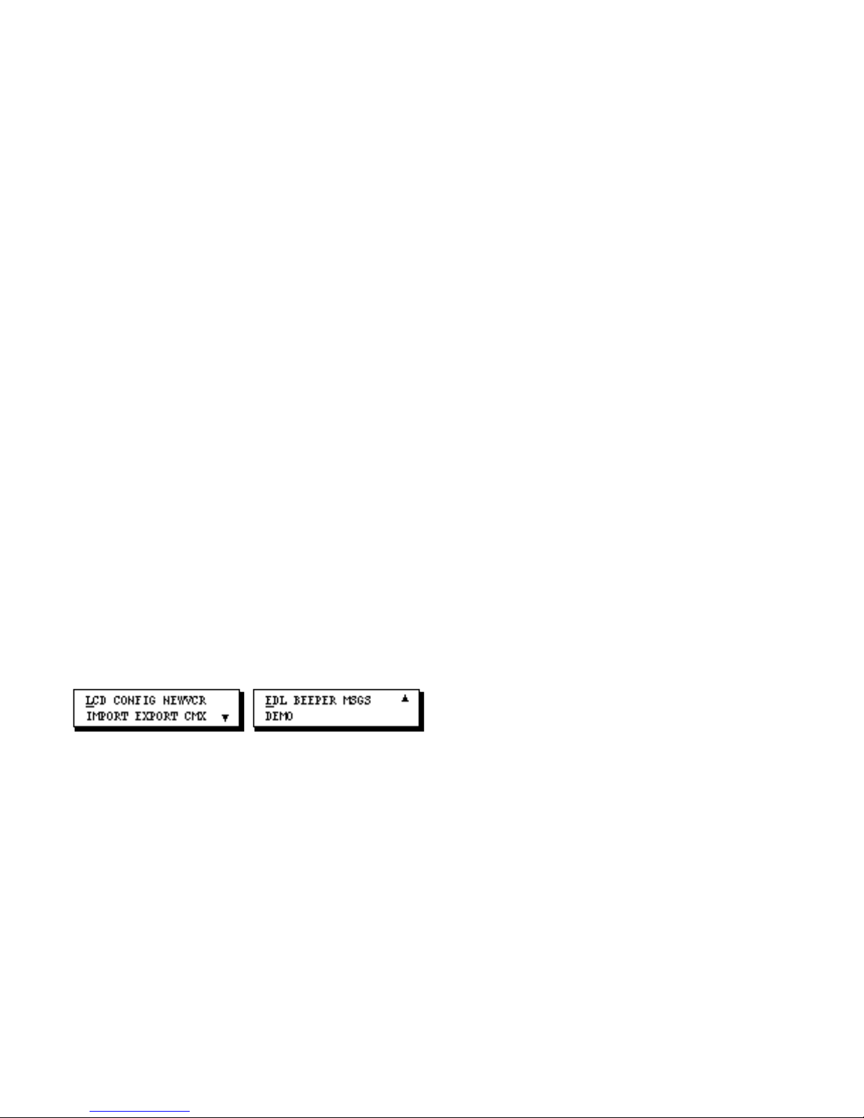
Chapter 9 • Setup and Configuration
Menus
This chapter describes the choices in the Setup and Configuration Menus.
Setup Menus
The Setup Menus access functions that are used to–
• change the LCD viewing angle
• turn on or off the beeper, error message text and the demo
• import and export the EDL to a personal computer
• add new VCR table definitions provided by Videonics.
The Setup Menus are also used to access the Configuration Menu. This menu is used to configure Edit
Suite's VCR and GPI ports so they can be used with your VCRs, camcorders, mixer and titler.
To display Setup Menu 1, press [SETUP].
Setup Menu 1 Setup Menu 2
To move between Setup Menu 1 and 2, press the [up/down arrow] keys.
To exit the Setup menus, with either Setup Menu 1 or 2 displayed, press [SETUP]. You are returned to
the EDL event you were viewing before [SETUP] was pressed. If there are no events in the EDL, the
NEW Menu displays. See Chapter 5 for a description of the NEW Menu.
To exit Setup from the Configuration Menu, press [SETUP] to return to Setup Menu 1, then press
[SETUP] again to return to the EDL.
To select a Setup function or to display the Configuration Menu, use the [left/right arrow] keys to
Page 91
move the cursor to the choice you want, then press [OK].
LCD Changes the viewing angle for the LCD. To adjust the angle,
change the LCD Contrast value from its default of 1 to a new
value.
To change the value, first move the cursor to LCD and press
[OK] to display the LCD Contrast screen. Next, press [CHG]
and turn the jog until the setting you want is displayed. Press
[OK] to save the new value and return the Setup Menu 1.
CONFIG Selects the Configuration menu and parameters. The
configuration parameters identify the devices attached to
Edit Suite, and provide instructions for communicating with
each device. The configuration parameters are described in
the next sections.
NEWVCR Adds new VCR tables to Edit Suite. From time to time,
Videonics may create tables to support new VCRs or VCR
protocols. These tables can be added to Edit Suite by typing
in strings of numbers provided by Videonics or by sending a
file to Edit Suite from a PC. Instructions for using the
function will be provided with the table data.
If you inadvertently access this function, press [CHG] and
wait for the 10-second timeout to be returned to Setup Menu
1, or press the POWER button twice to recycle power to Edit
Suite.
IMPORT Imports to Edit Suite a previously exported EDL and the
associated VCR configuration data. This replaces all current
EDL and configuration information with the information
from the imported file. See Chapter 8 for details.
EXPORT Exports the EDL and deck configuration information to a
personal computer. See Chapter 8 for details.
CMX Exports the EDL data, in CMX format, to a computer. See
Chapter 8 for details.
Setup Functions
The following table briefly describes each of the EDL functions.
Page 92
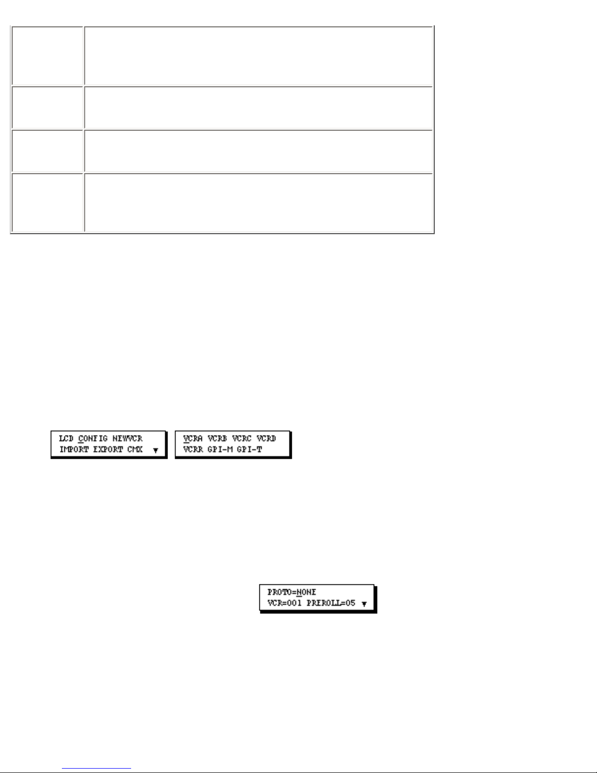
EDL Deletes all events in the Edit Decision List. After the events
are deleted and the Setup menus are exited, the New Menu
displays.
BEEPER Turns on (1) or off (0) the beep function for confirmation
and/or error conditions.
MSGS Turns on (1) or off (0) the wording that accompanies error
and advisory messages.
DEMO Turns on (1) or off (0) the demo (scrolling feature list) that
displays when the power supply is connected to Edit Suite or
the POWER button is pressed.
VCR Configuration Menu and Parameters
The VCR Configuration Parameters are used to configure Edit Suite's VCR Control Ports (A, B, C, D
and REC) so that the correct commands are sent to each of your VCRs and camcorders.
To display the Configuration Menu, from Setup Menu 1, move the cursor to CONFIG and press [OK].
To return to Setup Menu 1 from the Configuration Menu, press [SETUP].
Setup Menu 1 Configuration Menu
To access the Configuration Parameters for a VCR port, in the Configuration Menu, move the cursor to
the VCR port you want to configure and press [OK]. The first Configuration Parameter screen for that
VCR port displays.
To return to the Configuration Menu from the Configuration Parameters, press [SETUP]. When you do
this, Edit Suite saves your changes and builds a Control Table for the VCR port. Depending on which
parameters were changed, it may take several seconds for Edit Suite to build the VCR Control Table.
During this time, a spinning "wait" indicator displays in the bottom row of the LCD near the right side.
Page 93
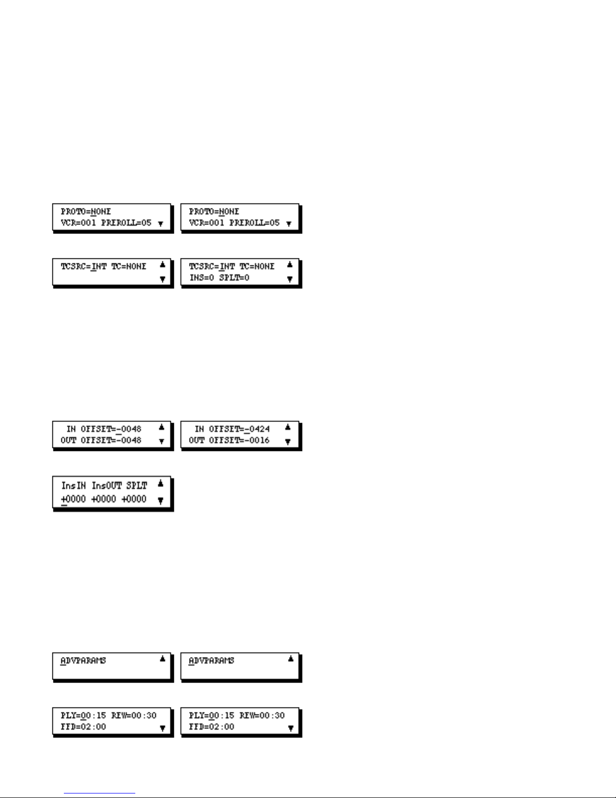
Configuration Parameters
The Configuration Parameters are divided into three groups: VCR Definition, VCR Tuning, and VCR
Search. There are a few more parameters for the record VCR than for the Play VCRs.
VCR Definition Parameters
Play VCRs/Camcorders Record VCR
VCR Tuning Parameters
Play VCRs/Camcorders Record VCR
VCR Search (Advanced) Parameters
Play VCRs/Camcorders Record VCR
Page 94
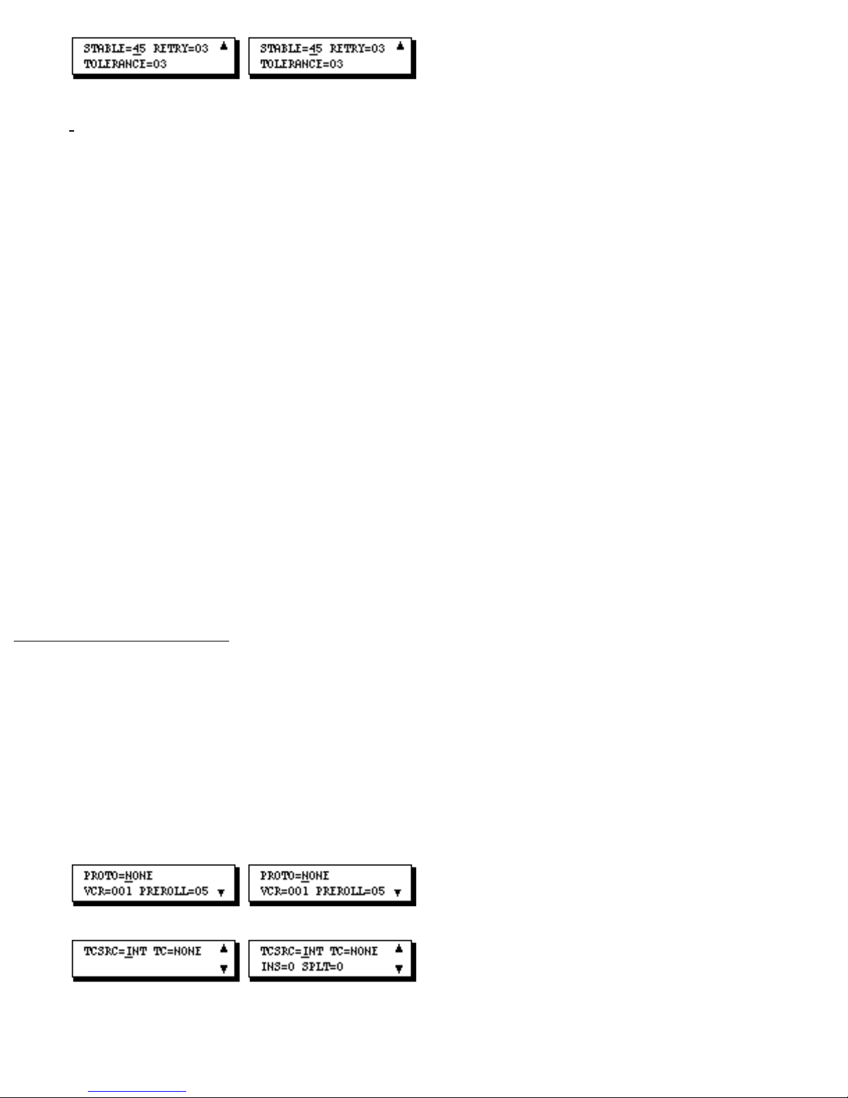
• To move between the parameter screens, use the [up/down arrow] keys.
• To access the VCR Search parameters, from the ADVPARAMS screen, press [OK].
• To return to the ADVPARAMS screen from the search parameters, press [SETUP].
• To return to the Configuration Menu from the Definition or Tuning Parameters, press
[SETUP].
• To change the PROTO (protocol), TCSRC (time code source), TC (time code type)
values, INS (insert) or SPLT (split insert) choices, press [CHG] to cycle through the list of
choices. If RS-232 (232) protocol is selected, choice lists for Baud Rate and Character
Format also display. If the Record VCR uses IR protocol, a choice list for the command
used to change from Record Pause to Record displays.
• To change any other parameter value, move the cursor to the field, press [CHG] to
activate the numeric keys, then type a new value or use the jog/shuttle to change the
existing value and press [OK].
VCR Definition Parameters
The VCR Definition Parameters specify the type of protocol used by the VCR or camcorder, the VCR
table number used to control the VCR, the type of time code used, if any, and whether the time code is
delivered over the Edit Control Cable or an Audio/Video cable. The Definition Parameters also specify
the preroll duration and, for the Record VCR only, whether the VCR is capable of doing Insert Editing
and Split Insert Editing.
Play VCRs/Camcorders Record VCR
Page 95

•
PROTO (Protocol) is the type of control protocol used by your VCR or camcorder.
Check your VCR/camcorder manual to determine the correct choice. Choices are:
LANC Sony Control-L
PANA Panasonic Control-M
232 RS-232 (Baud Rate and Character Format choices
display)
422 RS-422
IR Infrared; Record VCR only. (CMD choices display)
NONE Not used, or a noncontrollable video source is
attached to the corresponding port on a mixer/switcher.
• VCR is the VCR Table number to use. See Appendix A for a full list of choices.
• PREROLL is the number of seconds the VCR/camcorder should preroll before a scene
is played. Typically this value is 05–five seconds. It may need to be increased to 12 for
play VCRs/camcorders if insert editing is used and a VCR with PANA protocol is the
Record VCR.
For Record VCRs, only VCRs that require a preroll are prerolled. For the most part, this is
VCRs with RS-422 protocol. Leave the value at 05.
• TCSRC (Time Code Source) and TC (Time Code Type). TCSRC specifies whether
time code is sent through the Edit Control Cable (INT) or through an audio/video cable
attached to the Time Code IN port (EXT). TC specifies the type of time code being used.
- If Time Code is not used, select TCSRC=INT and TC=NONE.
- For most RS-232 and RS-422 VCRs, select TCSRC=INT and TC=NONE, VITC,
LTC or RCTC, depending on which time codes are available and selected on the
VCR.
- For LANC VCRs and camcorders with RCTC, select TCSRC=INT and
TC=RCTC.
- For LANC and PANA play VCRs with VITC or LTC striped on the play tape,
Page 96
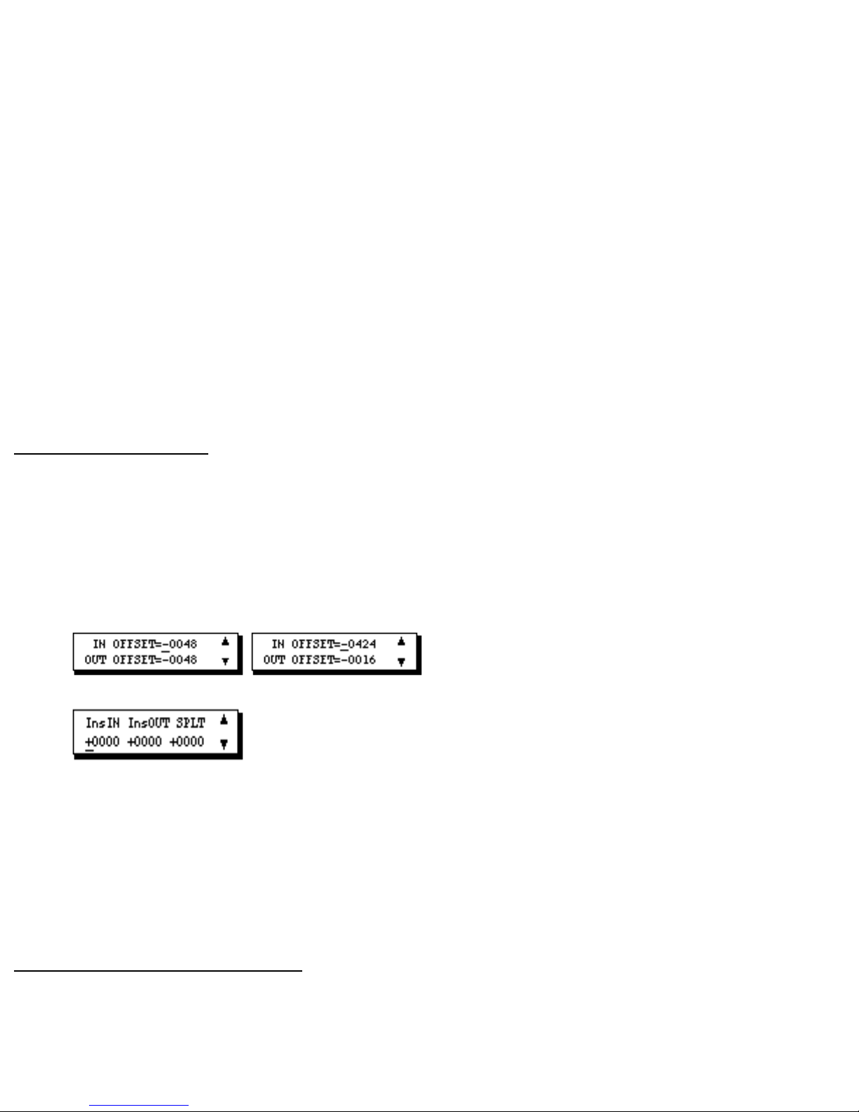
select TCSRC=EXT and TC=LTC or VITC.
- For LANC and PANA Record VCRs, select TCSRC=INT and TC=NONE.
If you select EXT, you must attach an audio (LTC) or video (VITC) cable from the VCR
to the appropriate Time Code IN port on Edit Suite.
See Appendix A for more information about the TCSRC and TC choices.
• INS (insert) and SPLT (split insert) are for the record VCR only, and specify whether
the VCR is capable of doing insert editing and split insert editing. 0=no, 1=yes.
Refer to the instruction manual for your record VCR to determine if it has these
capabilities. Refer to the Insert Event and the Split Insert Event sections of Chapter 5 for a
description of these features.
VCR Tuning Parameters
The Tuning Parameters are used to improve the accuracy of your edits. They adjust the timing Edit Suite
uses when it sends play, pause, record, and record pause commands to the VCRs during normal
recording operations. They also adjust the recorder timing when insert or split insert editing is done.
Play VCRs/Camcorders Record VCR
Procedures for adjusting the IN OFFSET and OUT OFFSET parameters are described in Chapter 7, Fine
Tuning. The InsIN, InsOUT and SPLT parameters adjust the timing for Inserts and Split Inserts. Refer to
the Insert Event and the Split Insert Event sections of Chapter 5 for a description of these parameters.
VCR Search (Advanced) Parameters
The Search Parameters control how Edit Suite searches for scenes when the GO TO function is used and
when an auto-record, preview, or review is done. These parameters tell Edit Suite when it should switch
Page 97
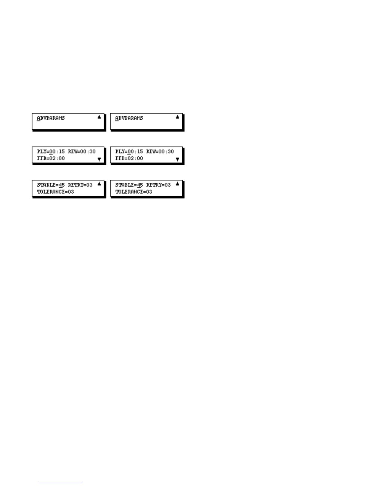
from Fast Forward to Cue and from Cue to Play. They also tell it how long to wait after issuing a Play
command before reading the time code, and how far to Rewind when the videotape is positioned close to
or beyond the search point.
To access the search parameters, display the ADVPARAMS screen and press [OK]. To return to the
ADVPARAMS screen from either of the Search Parameter screens, press [SETUP].
Play VCRs/Camcorders Record VCR
The PLY (play), REW (rewind), FFD (fast forward) and STABLE parameters are used when Edit Suite
controls the search process.
Most RS-232 and RS-422 VCRs control their own searches, so these parameters are ignored–unless RS232 table 006, 021 or 024 is used or RS-422 table 021 is used. These tables are used if external LTC or
VITC is used with an RS-232 or RS-422 VCR, in which case Edit Suite needs to control the search
process.
The default values for the search parameters will work for most VCRs and camcorders; however, you
may need to adjust the parameters if Edit Suite misses or is late starting a scene during a preview or an
auto-record.
When you adjust the parameters, observe the following precautions:
• PLY (play) should never be less than 10; the recommended minimum is 12.
• PLY must be less than or equal to REW (rewind).
• PLY and REW must be less than FFD (Fast Forward).
• Increasing STABLE also requires an increase in PLY. For every increase in STABLE by
Page 98

10, increase PLY by 1.
• If External VITC or LTC is NOT being used, STABLE may be decreased from its
default value of 45 to a value of 15. If STABLE is decreased to 15, PLY may be
decreased to 12.
• STABLE should not be decreased to a value less than 15.
• With REW set to 30, the earliest scene you can mark on a tape is approximately 45
seconds to one minute from the start of the tape. If REW is decreased, scenes may start
earlier on the tape by a corresponding amount.
• REW may be set as low as PLY (12-15); however, decreasing REW may prevent Edit
Suite from rewinding far enough to reach the search point–in which case the scene will be
missed.
At the start of a search, if external LTC or VITC is used, Edit Suite issues a Play command, waits for the
stable period (approximately 1/10th of a second times the STABLE value), and then reads the VITC or
LTC. This allows enough time for the VCR to change to Play speed from Stop, Fast Forward, etc., and
to be delivering readable time code data. Edit Suite uses this new reading of the time code to determine
the relationship between the time code and the real time counter for the VCR.
Next, Edit Suite determines which way it needs to move the VCR transport. It does this by comparing
the current time with the search point. For a GO TO, the search point is the IN or OUT point of the
current event plus or minus the OUT OFFSET amount for the VCR. For a preview or an auto-record, the
search point is the IN time for the event minus the PREROLL time, plus or minus the OUT OFFSET
amount for the VCR.
If the tape is more than two minutes (the FFD value) earlier than the search point, Edit Suite issues a
Fast Forward command to the VCR. When it reaches the FFD value, a Cue command is issued. The
VCR will remain in Cue until it is approximately 15 seconds (the PLY value) from the search point.
When the PLY value is reached, Edit Suite issues a Play command, waits for the stable period, reads the
time code and real time counter values, and makes any final adjustments necessary to reach the target.
If the tape is between the FFD and the REW parameter values when the search is started, the search
begins with a Cue instead of a fast forward.
If the tape is closer to the target than the REW value or if it is beyond the target, Edit Suite issues a
Rewind command. The VCR stays in Rewind until the tape is at least the REW parameter value away
from the target. A Cue is then issued, followed by a Play when the PLY value is reached.
Page 99
RETRY and TOLERANCE should not be modified. Leave them set to 03.
This table summarizes the initial settings to use for VCRs and Camcorders with LANC, PANA, RS-232
and RS-422 protocol. Refer to Appendix A for more information about the VCR Definition Parameters
and the VCR tables to use.
VCR Configuration Parameters
Parameter Initial Values for Each Protocol Type (Except IR &
Name None)
PROTO LANC* PANA 232 422
(protocol)
VCR (VCR table 001 - VCRs 001 001 - Sony 001
number)
002 - 003 - Panasonic
Camcorders
004 - JVC
007 - CCDV5000
012 - Canon
PREROLL 05 05 05 05
TCSRC (Time Code INT (for real INT (for real INT INT
Source) time counter or time counter )
RCTC)
EXT (for
EXT (for VITC or LTC )
VITC or LTC)
TC (Time Code Type) NONE
[Use NONE if Real RCTC
Time Counter is to be
used.]
VITC
NONE NONE
VITC RCTC
LTC VITC
NONE
VITC
LTC
LTC
INS ( VCRR Only) Is record deck capable of Insert Edits? 0 = No, 1 = Yes.
SPLT (VCRR Only) Is record deck capable of Split Insert Edits? 0 = No, 1 = Yes.
LTC
Page 100
IN OFFSET
-0048 -0048 -0048 -0048
- Play Decks -0424 -0424 -0424 -0424
- Record Deck
OUT OFFSET
- Play Decks
- Record Deck
InsIN (VCRR Only) +0000 -1340 for PAL +0000 +000
InsOUT (VCRR +0000 +0000 +0000 +0000
Only)
SPLT (VCRR Only) +0000 +0000 +0000 +0000
ADVPARAMS Press [OK] to access the remaining parameters.
PLY (play) 00:15 00:15 00:15 00:15
-0048 -0048 -0048 -004
-0016 -0016 -0016 -0016
-1608 for
NTSC
Press [SETUP] to return to the ADVPARAMS tile.
8
0
REW(rewind) 00:30 00:30 00:30 00:30
FFD (fast forward) 02:00 02:00 02:00 02:00
STABLE 45 45 45 45
RETRY 03 03 03 03
TOLERANCE 03 03 03 03
Note: For LANC VCRs with RCTC, if the VCR/camcorder counter goes blank or skips values when it is
in Fast Forward or Rewind, use VCR tables 121-126 instead of the tables listed above. See Appendix A
for more information.
 Loading...