

Page 1
Page 2
I. Connecting the Device.
No.
E series
EL series
1
Power Connector and Switch
Power Connector
2
BNC camera inputs 4/8/16 channel
BNC camera inputs 4 channel
3
BNC camera outputs
BNC output 1
BNC camera outputs
BNC output 2
BNC output 2
BNC output 1
4
VGA output
VGA output
5
USB and Network connector
USB and Network connector
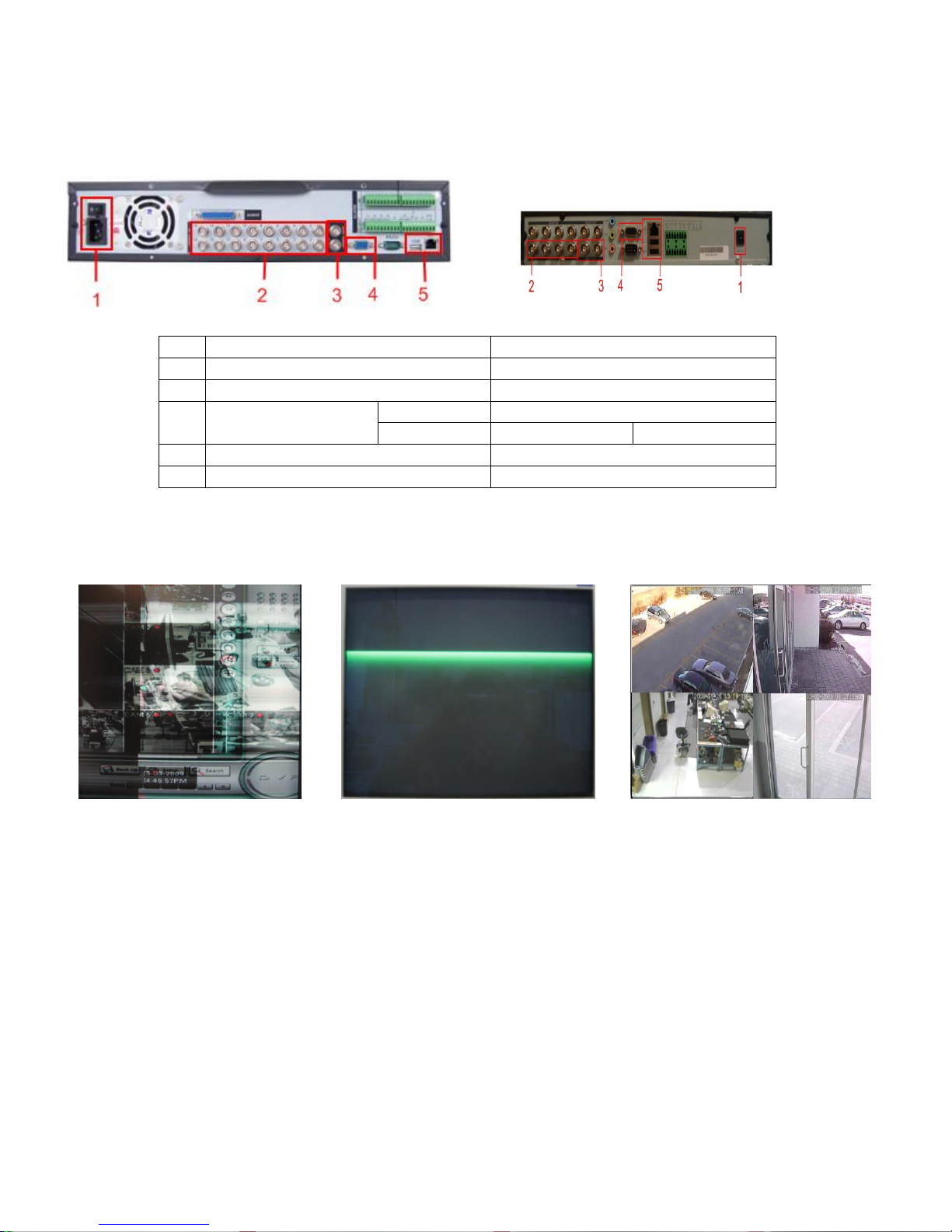
Before powering up the system make sure to connect the video inputs/outputs, network cable and usb mouse.
Refer below for basic connection.
Regular E series Embedded DVR EL series
The Video output on the embedded system can work by pair, BNC output 2 will work with either VGA or BNC
output 1, but VGA and BNC output 1 will not function together. And BNC output 2 will only display cameras with no
control GUI, it will only follow what is on the main display The Embedded system from manufacture default will always
use VGA as its primary output. When experiencing these types of display outputs from either BNC 1 and VGA.
A. Blurry or Overlapping video B. Center Green Line C. No GUI or Control GUI buttons
Blurry or Overlapping video happens when the DVR system uses the other video output, meaning if the monitor
is connected to the BNC output 1 but the DVR is set to uses the VGA out. While the Center Green Line, happens when
the DVR system is turned on with no VGA output connected. To set the DVR to the correct output, press and hold the
star or asterisk button on the regular E series and the shift button for EL systems.
For the No GUI or Control buttons move the video BNC connector to Video BNC output 1.
Page 3

II. How to connect the DVR to the Network and Internet.
1. Network Address.
User must assign an Ip address, subnet mask and gateway. To know what network settings to use, do a ipconfig
on command prompt or get the network status of your existing computer.
ipconfig result network status
The Subnet Mask and Default Gateway will remain the same on the DVR but the IP address would be different mainly
the last octet or number, each device on the network must have its own unique IP address. On the example the IP
address is 192.222.221.10, 10 being the last number. So assign to the DVR any last number between 2-9 and 11-254.
To assign the ip address click on then then , network setting interface as shown
After assigning the IP address save the settings by clicking Save button, then do a menu restart.
note: If router has DHCP enable make sure to stay away from the DHCP range to prevent network conflicts.
Page 4
2. Port forwarding.
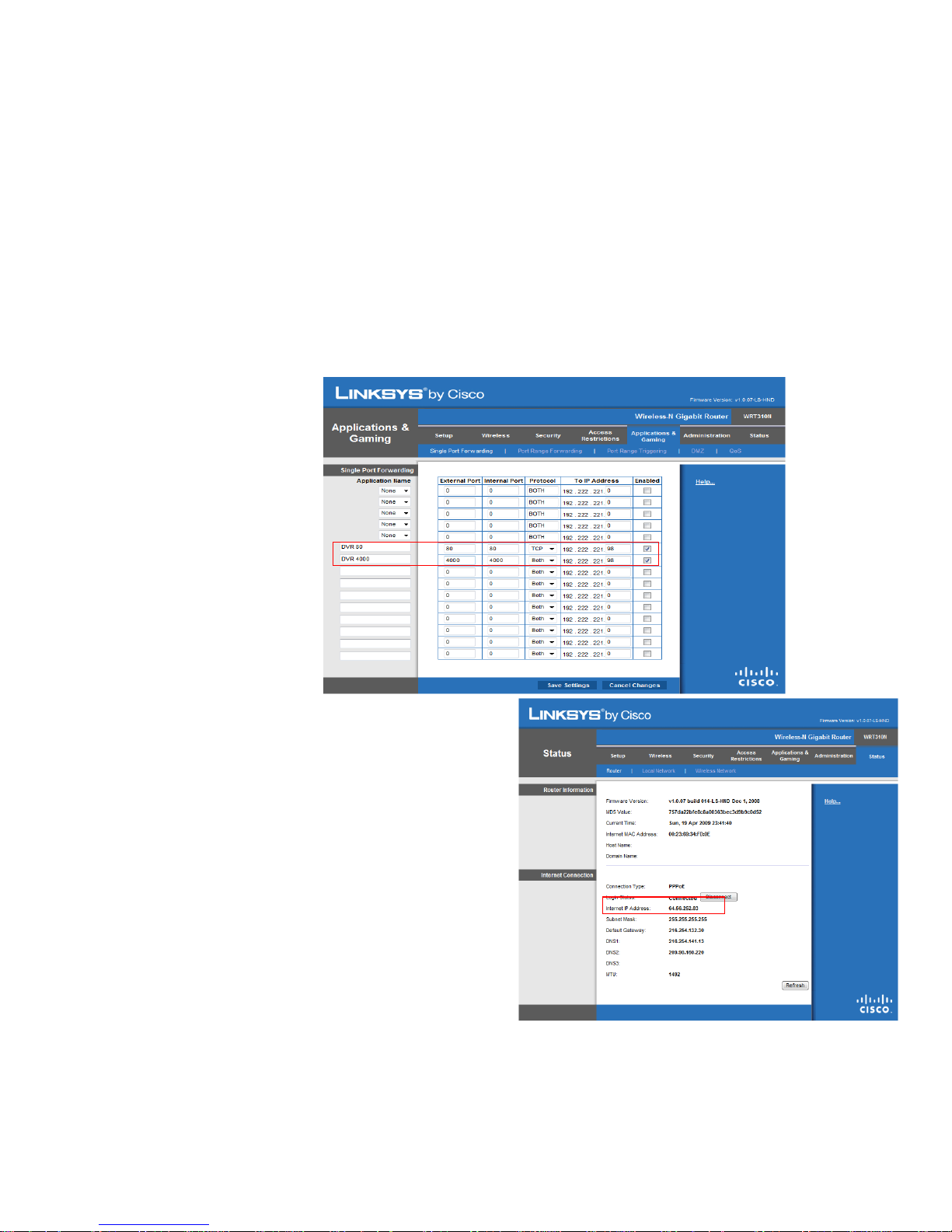
To access the DVR over the internet user must forward the HTTP port and TCP port. Each router has a unique
way of port forwarding some routers call it pin holes or virtual server but all of them will always have a common
requirement. As an example a Linksys router is used.
1. Name - User can use any name - ex. DVR 80 and DVR 4000
2. Device IP address - the embedded DVR IP address - ex. 192.222.221.98
3. ports to forward - 80 HTTP port and TCP 4000 - ex. 80 and 4000
- external/public port - 80 and 4000
- internal/private port - 80 and 4000
- port range - 80 to 80 and 4000 to 4000
4. source IP address - if user knows the IP address that will connect to the DVR or use the default which would be any
On the status page of the router make sure the it contains the
public IP address. If the Internet/WAN IP address starts with
192 or 172 or 10, it means the ISP modem is routing not
bridging. Please contact the Internet Service Provider to bridge
the modem.
Page 5
3. DDNS
Click OK
Login
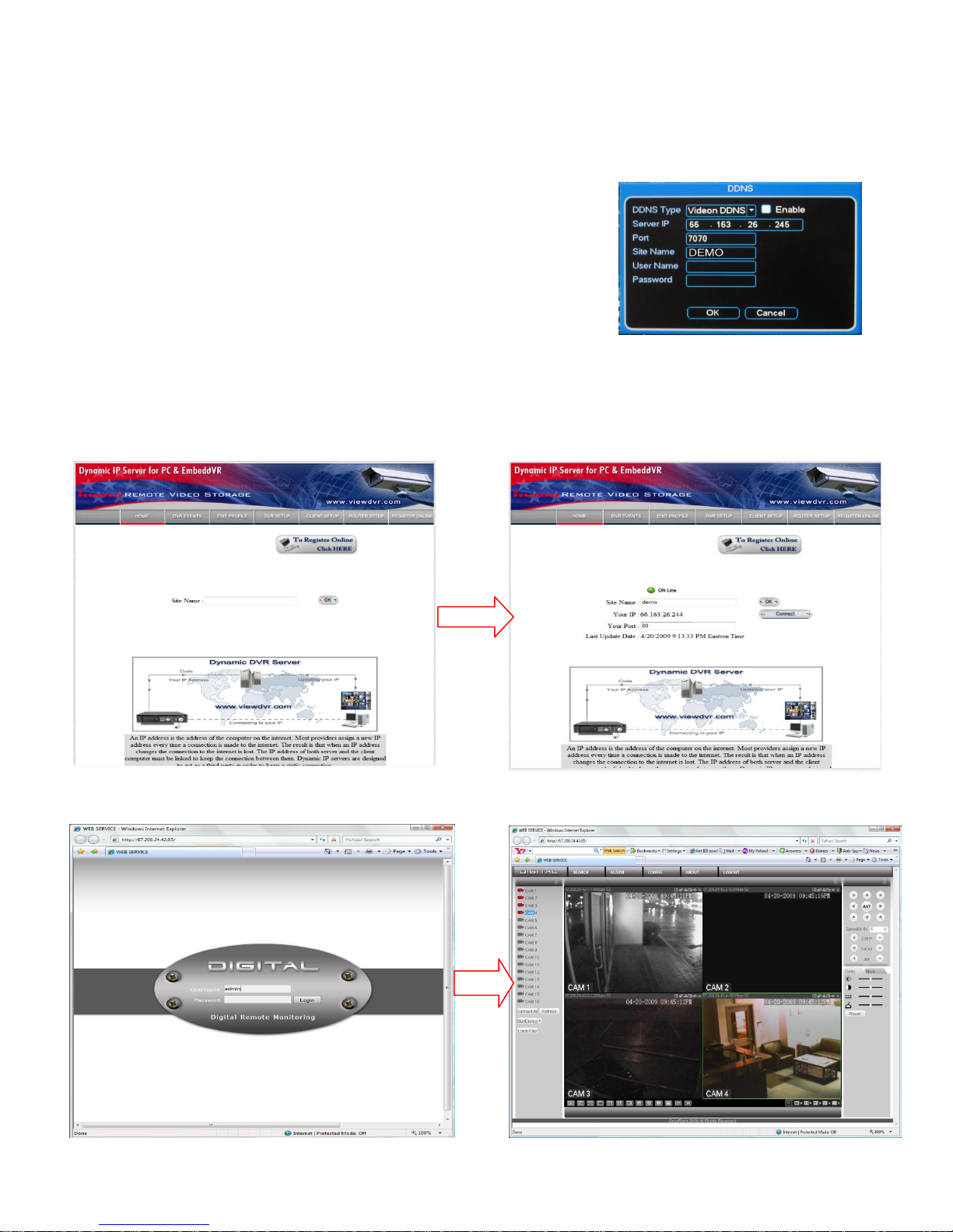
If the public IP address is dynamic meaning it changes from time to time. User would need a dynamic dns service
provider, so that the DVR will still be accessible even when it changes IP.
A. Register with www.viewdvr.com and remember the Site Name which is needed on the Embedded system
B. Input these settings on the Embedded systems DDNS
Server IP - 66.163.26.245
Port - 7070
Site Name - the site name that was registered in www.viewdvr.com
Username - leave blank if using Videon DDNS
Password - leave blank if using Videon DDNS
note: Always register a new Site Name when installing a new system.
4. Remote Connection
There are two ways to connect to the Embedded DVR.
4.1 Using IE go to www.viewdvr.com type in the site name and click ok
Click Connect to open the Web View. Input user name and password and click login
default username: admin default password: 1234
Page 6
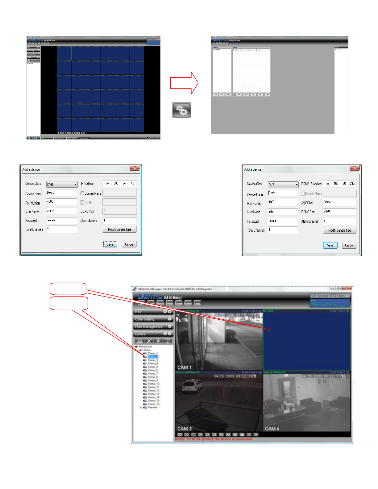
4.2 Multi-site Manager
Click
Click next
Click 1st
Install the Multi-site Manager and add the Sites.
On the Add Menu user can add the device they need to connect too.
Device name: Any Name
Port: Service/TCP Port
User Name: Use to login on DVR
Password: Use to login on DVR
Total Channel: number of cameras
IP Address: Public IP address of the DVR or
DDNS server IP 66.163.26.245
Domain Name: Domain name of the DVR
DDNS: DDNS Site Name of the DVR
DDNS Port: for Viewdvr it is 7070
Alarm channel: no. of alarms on the DVR
Example 1. By Direct IP address Example 2. By DDNS
After adding the Site Click on the connect button and click the on 1 of the viewing window and click on
Page 7
III. Setting the DVR Schedule
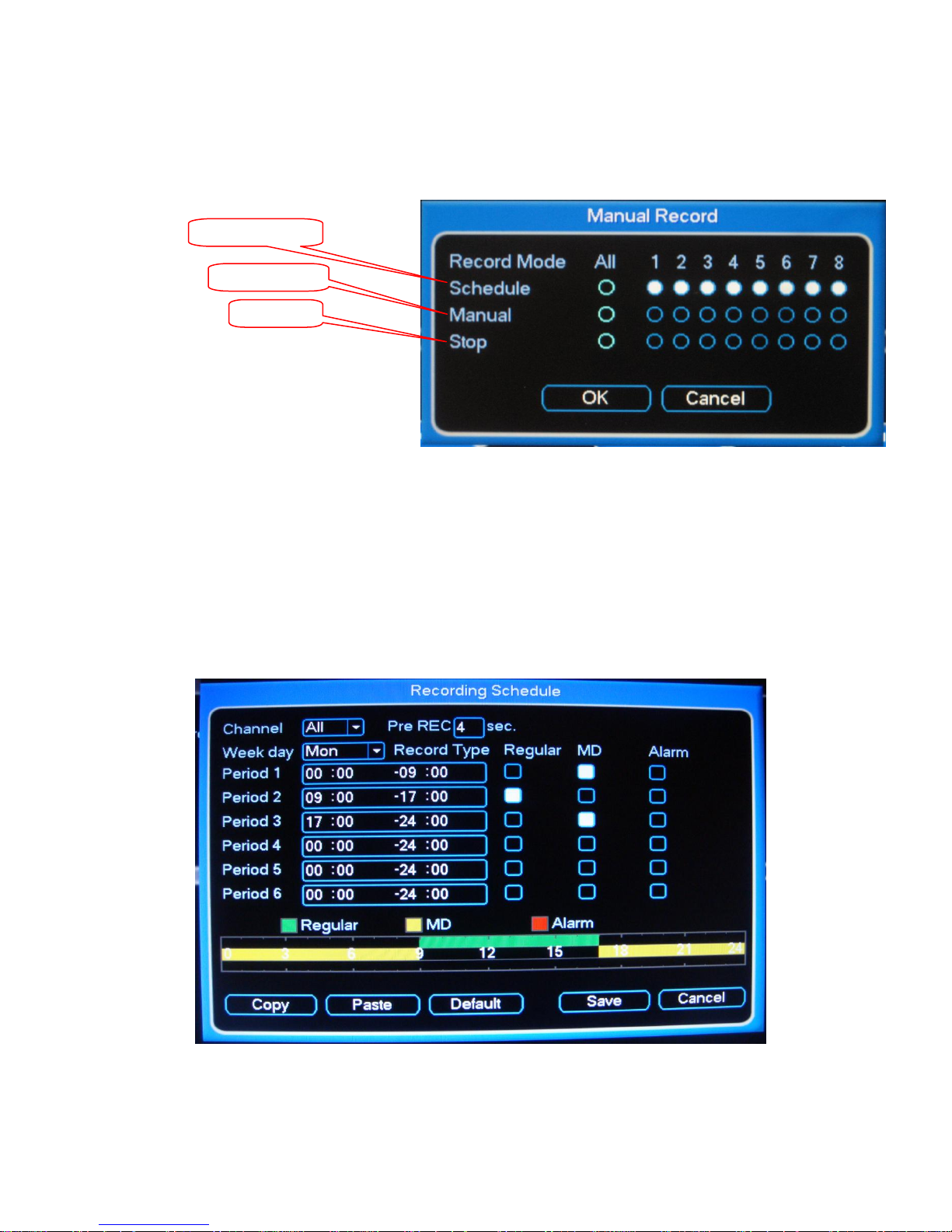
Scheduled Recoding
Always Record
Stop
1. Manual Record.
To open the Manual Record menu and enable Scheduled Recording, on the Main Menu select Advance
Setup and then click on Manual Record or on the front panel of the DVR press the REC button. On the Manual
Record window High light “All” on Schedule. Click OK
2. Setting the Schedule:
Example 1. Schedule the DVR to Regular recording (always record) from 9:00am to 5:00pm and
Motion recording for the rest of the day. And for weekends Motion Recording for 24hrs.
Open the Recoding Schedule Menu
Set the Schedule for Monday and for All cameras.
For Period 1 set the time from 00:00 to 09:00 then highlight MD for Motion Detection.
For Period 2 set the time from 09:00 to 17:00 then highlight Regular
For Period 3 set the time from 17:00 to 24:00 then highlight MD for Motion Detection.
Press Copy button.
Select the next day Tue (Tuesday) for Week day, then press the Paste button. The schedule for Tue
will now look like the schedule for Mon. Repeat the process until all the week days are set to the
schedule.
Page 8
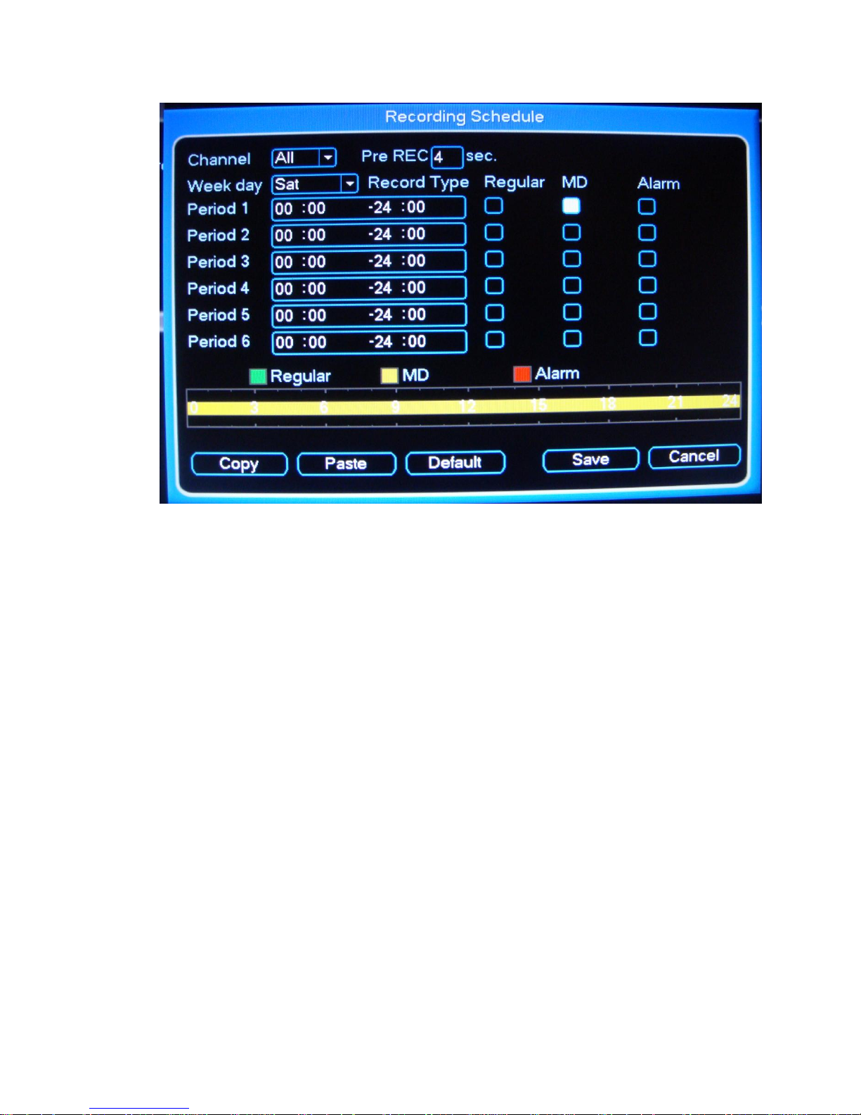
To set Motion only for the weekends or for Saturday and Sunday. Select Sat on the Weekday field
and All for channel field. Then for Period 1 highlight only MD.
Then Copy and Paste to the Sunday field
Page 9
IV. DVR Search & Backup Procedures
3.1
3.3
3.1 3.1
Click to start
backup
USB Drive or CDRW/DVDRW
Before beginning any backup procedures, make sure to have the CD’s, DVD’s and USB drives that
is supported by the DVR. The DVR's drive tray will show what type of media it supports, if it shows only CD it mean will
only support CD's but if it shows DVD and CD it can support both media. Make sure to insert the CD, DVD or USB drive
before starting the backup procedure, connecting it while in the backup window may cause it not to be detected nor
seen. For USB drives make sure that the drives are in FAT32 format.
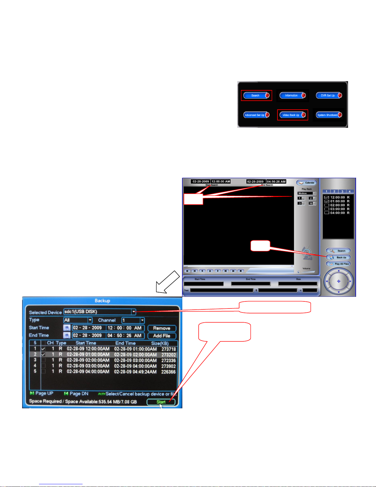
There are two ways to start a backup, highlighted below, they are:
Searching for the video you wish to backup in the “Search” window
Searching by time and date in the Video Backup menu
The following steps will guide you through backing up the files from the “Search” window:
1. Login to the DVR. Pressing the login button
2. Enter the Username/Password. (Default: admin / 1234)
3. Select “Search” this will open the Search Window
3.1 Enter the time/date at the top-left corner,
and the channel numbers you want to view
on the top-right.
3.2 Place a check next to the videos you want
to save using the file list on the right.
3.3 Select the “Back Up” button on the top
right, this will open the backup window as
seen below
 Loading...