

VIDEOMAN VS-902, VS-902C, VS-902M, VS-902PSU, VS-902P User Manual
...
VIDEMAN is a registered trade mark of EOS Australia Pty Ltd
Designed, imported and distributed by Videoman Systems Co.
VS-902
B&W 16VDC VS-952 Colour 16VDC
( VS-902M + VS-902C + VS-902PSU ) ( VS-952M + VS-952C + VS-902PSU )
VS-902P
B&W 240VAC VS-952P Colour 24VAC
( VS-902PM + VS-902C ) ( VS-952PM + VS-952C )
060911.67 www.videoman.com.au
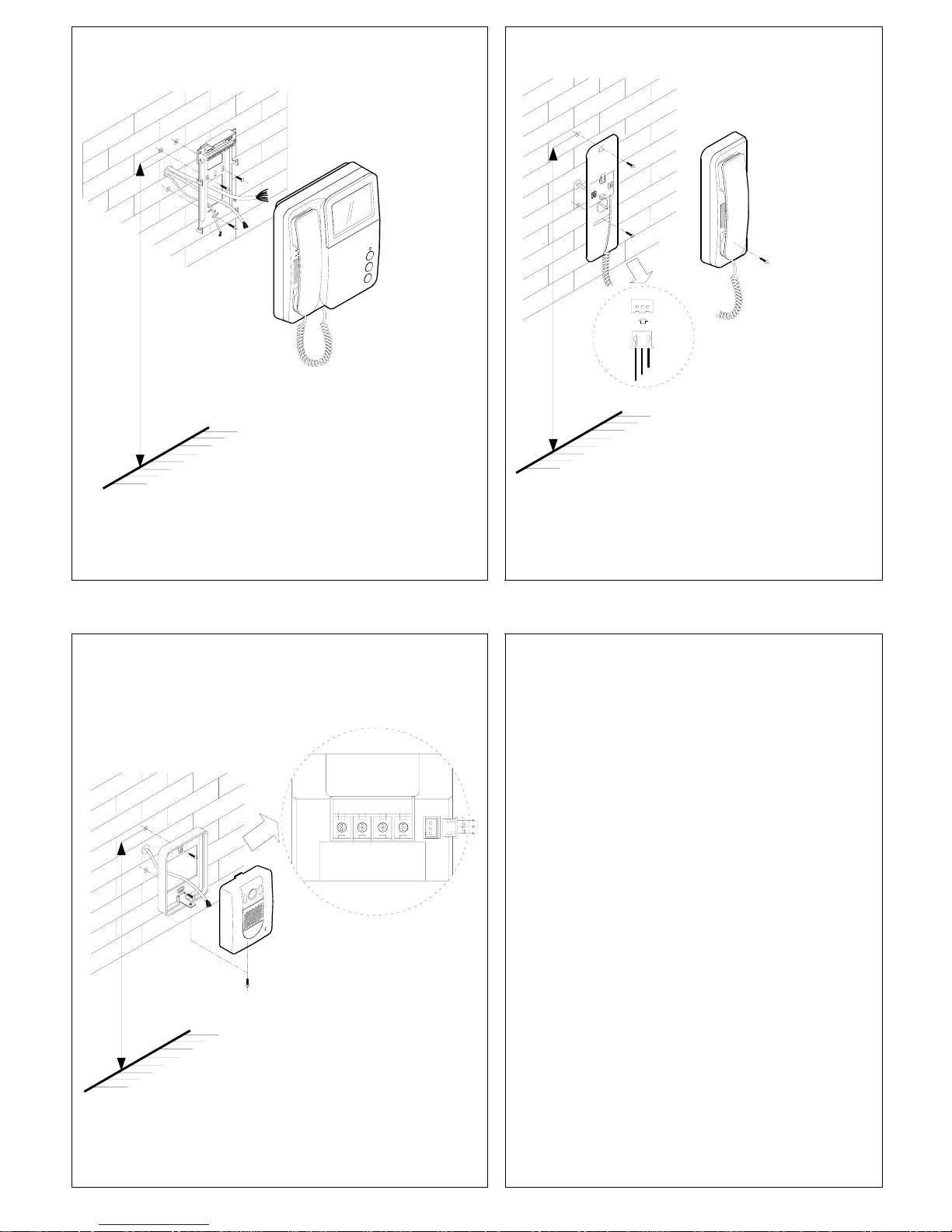
Indoor Monitor(Ref VS-902M) Installation
Fig. 1
155 Cm
Audio Handset (Ref VS-902H) Installation
Fig. 2
155 Cm
Surface Mount Camera(Ref VS-902C)Installation
4B3Y2W1R LB
155 Cm
Fig. 3
Install indoor monitor, outdoor camera or audio handset about
1.55M~1.60M from the ground and keep away from snow,
rain and direct sunlight.
NOTE : Optional angle brackets are available for surface
mount cameras
45Degree left/right : Ref VS-902AB45
15Degree left/right : Ref VS-902AB15
Page1
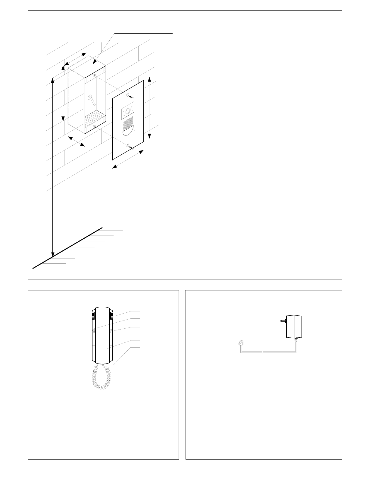
Flush Mount Camera (Ref VS-902MC) Installation
Fig. 4
160 Cm
13
0
mm
200mm
175mm
7
0
m
m
1
0
0
mm
Ref. No: VS-902EB
Dimensions
Overall size of front panel :
130mm(W) x 200mm(H)
Cut out size without embedding box:
100mm(W) x 130mm(H) x 60mm(D)
Cut out size for embedding box (Ref VS-902EB):
100mm(W) x 175mm(H) x 70mm(D)
Descriptions of Audio Handset (Ref VS-902H)
1
3
4
5
2
Dimension: 215(H)x80(W)x45(D)
Fig. 5
Descriptions of Power supply (Ref VS-902PSU)
Fig. 6
16V DC 800mA SAA Approved
1. Loud Speaker for Ring Tone
2. “Intercom-Call” button
3. “UNLOCK” button
4. Handset
5. Spiral cord
The adaptor is only supplied with VS-902 and VS-952
( -- ) : Black wire : Surround
( + ) : White Stripe : Centre
For 240V AC model (Ref. VS-902PM, Ref.VS-952PM) connect the
monitor directly to 240V AC mains without 16V DC power supply
(Ref.VS-902PSU)
Page2
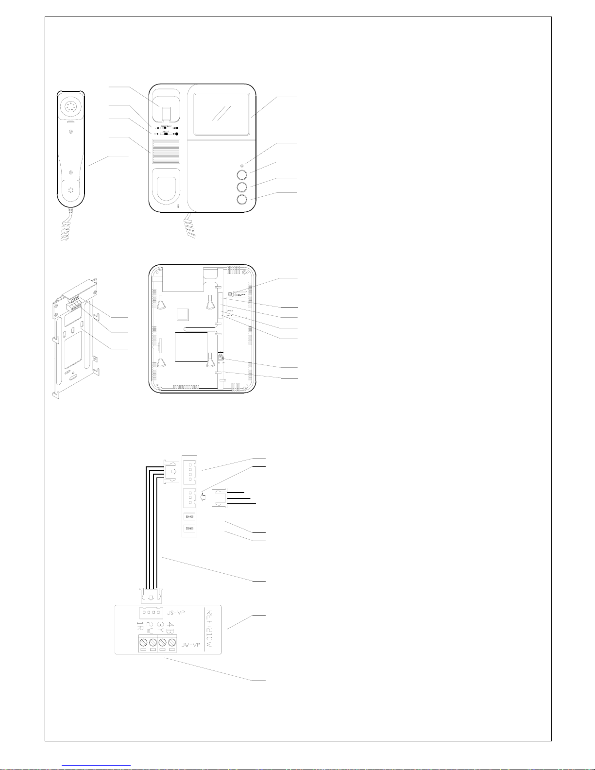
Descriptions of Monitor
16VDC Model (Ref.VS-902M B&W, Ref.VS-952M Colour)
240VAC Model (Ref.VS-902PM B&W, Ref.VS-952PM Colour)
10
1
3
4
5
2
9
7
8
6
11
15
14
13
16
19
20
18
12
17
Dimension:220(H)x190(W)x55(D) Fig.7
JP-VD
JP-LK
JS-AP
JS-VP
To Audio Handset
VS-902H
Fig.8
19
15
14
13
21
12
20
1. Screen
2. Power Indicator
3. “MONITOR” button (Refer to Page8)
Press to turn on monitor or switch the second camera if the
second camera is installed with a switcher (Ref:VS-2Way)
4. “UNLOCK” button (Refer to Page8)
5. “INTERCOM” call & Ring tone selection button
(Refer to Page8)
6. Handset
7. Loudspeaker for ring tone
8. Brightness adjustment
9. Contrast (Ref VS-902M/PM) or Colour(Ref.VS952M/PM) adjust
10.Craddle and Hook switch
11. Ringing volume adjust
12. JS-VP 4 pin port to Bracket Board(Ref VS-210W, VS-2Way)
13. JS-AP 3 pin port for Handset (Ref.VS-902H)
This connector is supplied with Ref VS-902H.
14. JP-VD Video impedance setting (Refer to Page5 Note2)
With Jumper : 75 Ω for the furthest monitor
(factory default is with Jumper)
Without Jumper : High impedance for other monitor(s)
15. JP-LK Unlock operation type setting
(Refer to Note Page4 #7, Page5 Note1,2,3)
With Jumper : Dry contact output from Camera’s
LB terminal (factory default)
Additional power supply is required for door latch with
this type of door latch operation.
Without Jumper : 12VDC Max.500mA output
to door latch from Camera’s LB terminal.
NOTE 1 : During unlock operation the screen will be
off if this mode is selected.
NOTE 2 : Do not use any electric door latch bigger
than 6W with this type of door latch operation.
16. DC input socket (Ref. VS-902M & Ref.VS-952M)
17. AC input cord (Ref. VS-902PM & Ref.VS-952PM)
18. Wall mounting bracket
(Single camera : Ref. VS-210W; Standard )
(With second camera : Ref. VS-2Way , Optional extra)
19. JW-VP wiring terminal to camera(s) & slave monitor(s)
20. JS-VP monitor terminal
21. 4 core connector with plugs (Ref. VS-4P)
Page3
 Loading...