

VIDEOMAN FUTURO-A4, FUTURO-A4M, FUTURO-A4C, FUTURO-7PS User Manual

VIDEOMAN is a registered trade mark of EOS Australia Pty Ltd
Designed, imported and distributed by Videoman Systems Co.
-A4 -A4M
Wide Screen Intercom Kit Kit Monitor only
(Inc. FUTURO-A4M, FUTURO-A4C, FUTURO-7PS) (Inc.FUTURO-A4M, FUTURO-7PS)
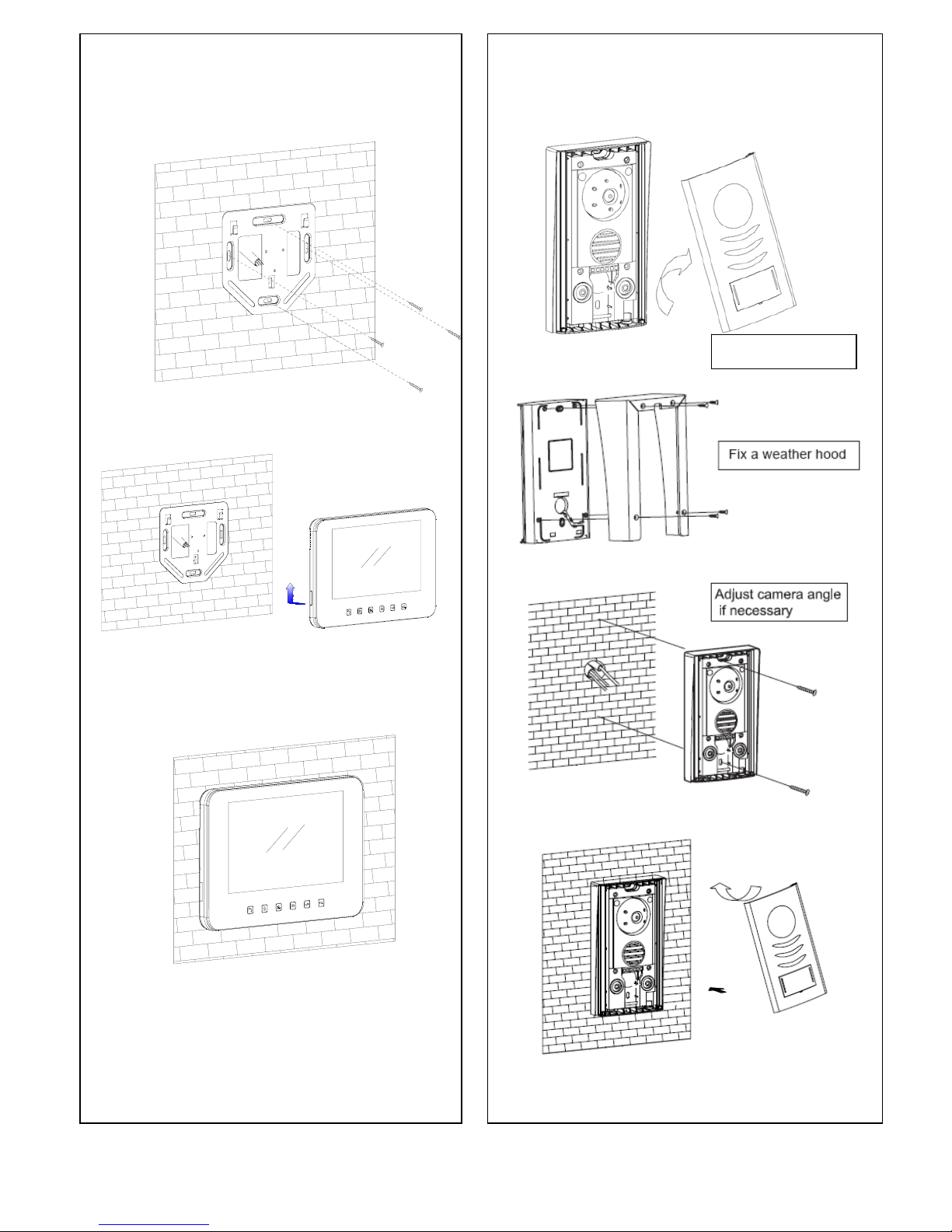
Indoor Monitor FUTURO-A4M Installation guide FUTURO- A4C Door Station Installation guide
Surface mount with optional FUTURO-A4WH
Fig.1 Fig.2
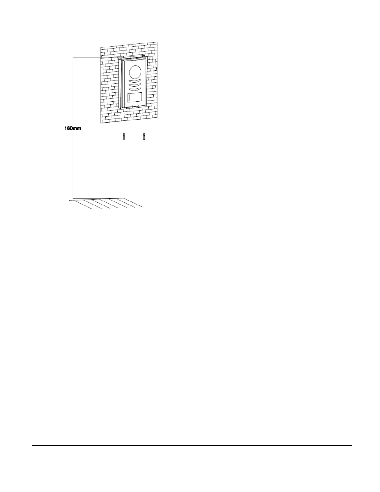
Install the door stations approx. 1.55M~1.60M from the ground Install the door stations approx. 1.55M~1.60M from the ground
Page 1
Remove front cover
FUTURO-A4C Door Station Installation Guide-Surface mount with optional FUTURO- A4WH
I
Install the door stations about 1.55M~1.60M
from the ground.
Keep the units away from snow, rain and direct
sunlight.
Dimensions
Overall size of front panel :
99mm(W)x181mm(H)x31mm(D)
Fig.3
FUTURO–A4C Door Station Installation and a Name Tag Holder assemble guide
1. Write desired name on the white plastic label provided.
2. Insert white plastic label into the clear plastic label holder.
3. Remove the front aluminum cover from the door station.
4. Insert the name tag holder into the black plastic from the back side
of the aluminum.
5. Install the door station back body to the wall.
6. Assemble the aluminum cover with 2 screws provided from the bottom of the doorstaion.
(Warning !! Be careful not to screw into a microphone hole)
Page 2
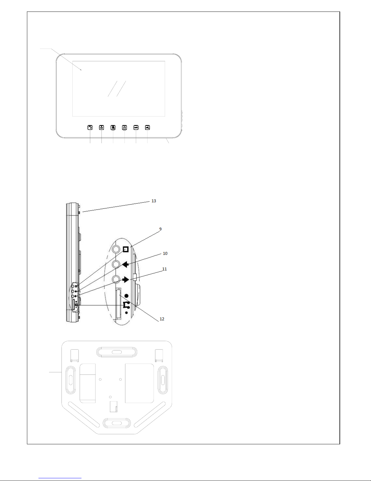
Description of Monitor FUTURO-A4M features
1. SCREEN
2. TALK / OFF / INTERPHONE / AUDIO BABY
MONITORING button
When monitor rings it activate a communication
line, and also to turn the screen off.
When it is on stand-by mode it activates
interphone communication and audio baby
monitoring.
3. MONITOR/SWITCH button
Press to turn on the monitor manually.
When it is on, you can switch the screen from
all the cameras that are connected to the
system. To turn off, press TALK button twice.
4. MUTE button
Press the button to mute the ring tone, press
it again to deactivate mute function.
5. Changing Ring Tone
When the monitor screen is off, press-and-hold
this button for 3 seconds to go into change ring
tone mode then press the MONITOR button to
select the ring tone. After selecting the ring
tone press the RING TONE button again to
exit.
6. DOOR OPEN button
7. CCTV function button
Press the CCTV button to activate auto switch
camera function. To deactivate press TALK
button.
8. MICROPHONE
9. MENU button
Controls brightness, contrast, colour when
monitor is on, and controls LED backlight when
is on stand-by mode.
10. Adjust left (only able to use in MENU function)
11. Adjust right (only able to use in MENU function)
12. Ring Tone Volume
Allows you to adjust the ring tone volume.
13. LED backlight
14. Wall mount bracket
Page 3
1
34567 82
16
14
MONITOR
1.
I
︵
VIDEO︶ 2. F︵AUDIO︶ 3. DATA 4. GND
AUDIO
1. B+
︵
+12
V︶ 2. AUDIO︶ 3. DATA 4. GND
POWE
R
1. B+ 2. B-
CCTV2
1. 2. GND
3. B 4. VIDEO
CCTV1
1. 2. GND 3. B 4. VIDEO
CAMER
A
2
1. AUDIO 2. GND 3. B 4. VIDEO
CAMERA1
1. AUDIO 2. GND
3. B 4. VIDEO
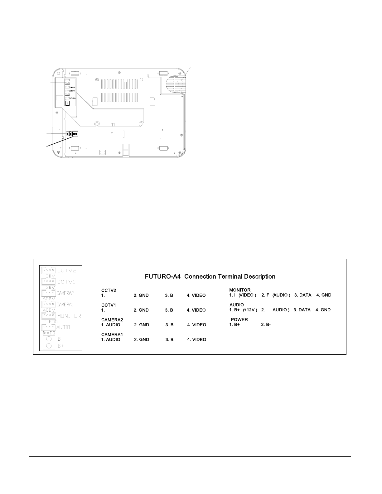
FUTURO-A4 Connection Terminal Descriptio
n
Description of Monitor FUTURO-A4M features (continue)
15. Connection Terminal.
Please see fig.4 for terminal description.
16. Speaker.
17. Master/Slave Settings.
The monitor that is connected to any camera
MUST set its’ two DIP switches to MASTER
position.
Rest of the monitor’s two DIP switches must
be set to SLAVE position
18. Camera Cycling Settings
Set the dip switch into ON position to have the
cameras cycling around.
e.g if you have 2 doorstation and 1 external
camera, you need to set the dip switch 1, 2
and 3 to ON position.
Fig.4
Page 4
13
16
CCTV2
CCTV1
INT1
BB+
GBV
GBV
AGBV
AGBV
I FDG
ADG
15
14
17
18
Fig 3
 Loading...