

Page 1
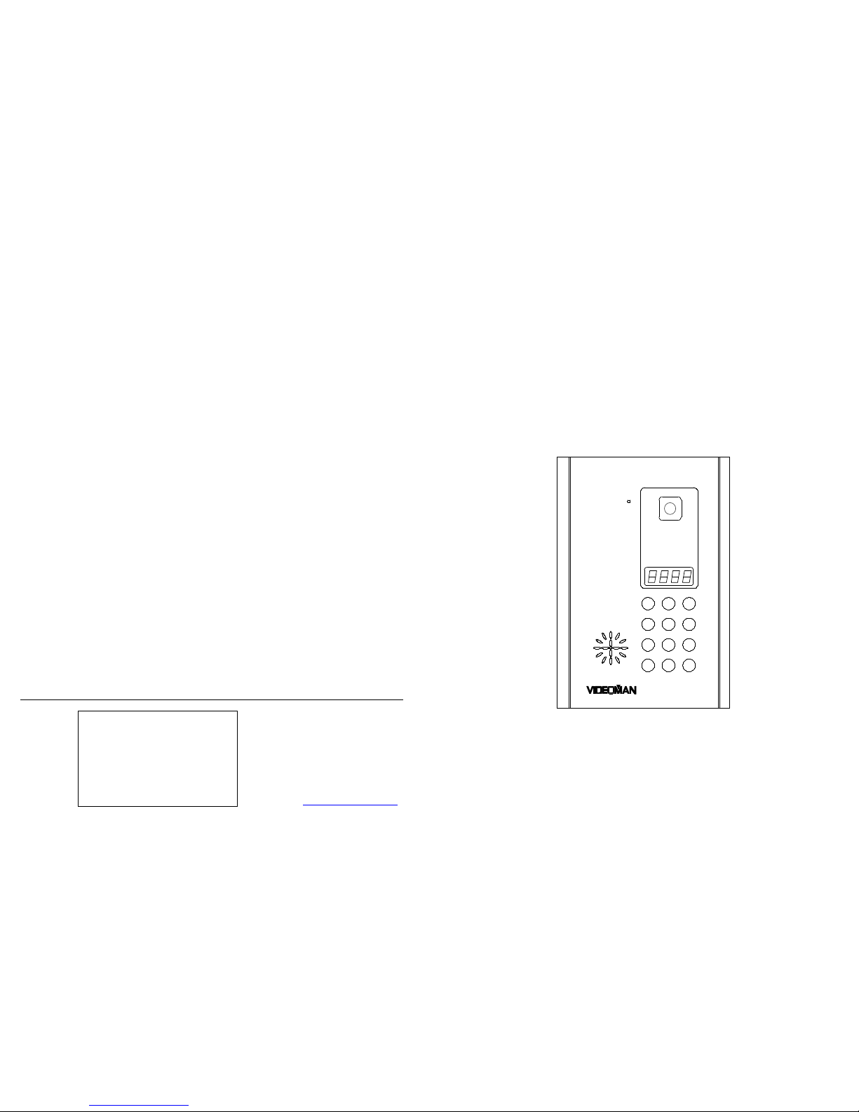
VIDEOMAN DIGITAL 700
With multiple Riser Port
1 2 3
4 5 6
7 8 9
0 #
*
VIDEOMAN SYSTEMS Co.
V 3.0 21/9/01
VIDEOMAN Systems Co.
Unit 13, 112 Benaroon Rd.
BELMORE NSW 2192
AUSTRALIA
Phone : (02)9758 9509
Fax : (02)9758 9510
e-mail: [email protected]
URL: www.videoman.com.au
Page 2
Page 1
V
ideoman Digital 700
INDEX
Contents Page
Features 2
Capabilities 3
Normal Operation 4 – 5
Mounting Entrance Station 6
General Wiring Guide 7
Wiring Requirement : Single Riser Configuration 8
Wiring Requirement : Multiple Riser Configuration 9
Connection Diagram 10 – 11
System Programming 12
Unit No. Programming 13 – 15
System Components 15 – 18
Special Extras 19
Project Data Note 19-22
Page 3
Page 2 Page 3
FEATURES
Microprocessor driven digital Video Intercom systems guarantees powerful and flexible
solution and simple installation on any video intercom applications.
Digital Video Entrance Station with key pads
Door Lock release – Normally open, Normally close
Adjustable door lock release time
LED indicator for caretaker’ s message
Coated metal finish Entrance station
User call by means of 4-digit numeric code established according to floor and apartment
Dedicated key for guard
Multiple Riser Output Port
The new Main Controller (TMC-750) now has 6 Decoder outputs, for buildings which
has more than 1 riser. This makes it possible to run cables in a STAR format, which in
return eliminates longer cable run than that it is necessary, and easier to run the
cables.
Call Restriction Capability by Individual Entrance Station to Each Riser Output Port
The other powerful feature of the new Main Controller is that, each decoder output can
be programmed independently, such as their unit numbers (Units) associated with that
riser. Each door station can only call the units within that block.
Up to 2 Audio Channels
Thanks to dual-audio channel capability, 2 conversations can be made within a system
simultaneously. Which means when someone engages the system another person can
make a call and talk to another handset simultaneously. This minimizes visitors having
to wait at the entrance.
Easy to install
Installation is simpler than ever.
If there are any wiring problems, only the monitors or sections will not operate properly.
Which eliminates huge time and effort in rectifying the problem.
Connectors for all necessary connection – no screws
Programmable lift controller
Each unit has its own level No. in programming procedure and relay operating time
and delay time is also programmable.
Internal communication between handsets to handsets
• Directly with optional TMN-710 or through the caretaker, Internal communication
between handsets to handsets can be made without any phone call charge.
• Direct communication from auxiliary phone TAP-700 at swimming pool, gym or
lobby to unit handsets or guard station is also made possible for resident’s
convenience.
Full software driven programming
Microprocessor and its software driven programming eliminate any mechanical DIP
switch setting for easy and one-step programming.
No programming on Handsets and decoders
Programming with large 8-digit displays on Display Unit.
Built in door opener function by password (Optional Extra)
Pressing a 4digit Password on Entrance Station at anytime can open door. Which
allows Keyless or Cardless entry to residents.
CAPABILITIES
Module
Model No. Max. No.
Main Controller
Video Entrance Station
Video Handset
Decoder
Lift Controller (Standard 16 Level)
Video Guard Station
TMC-700
TVE-700
TMN-700
TDE-700
TLC-700
TVG-700
1
4 ( up to32 with TEX-700)
500
50
2 ( up to 64 Level – Optional )
1
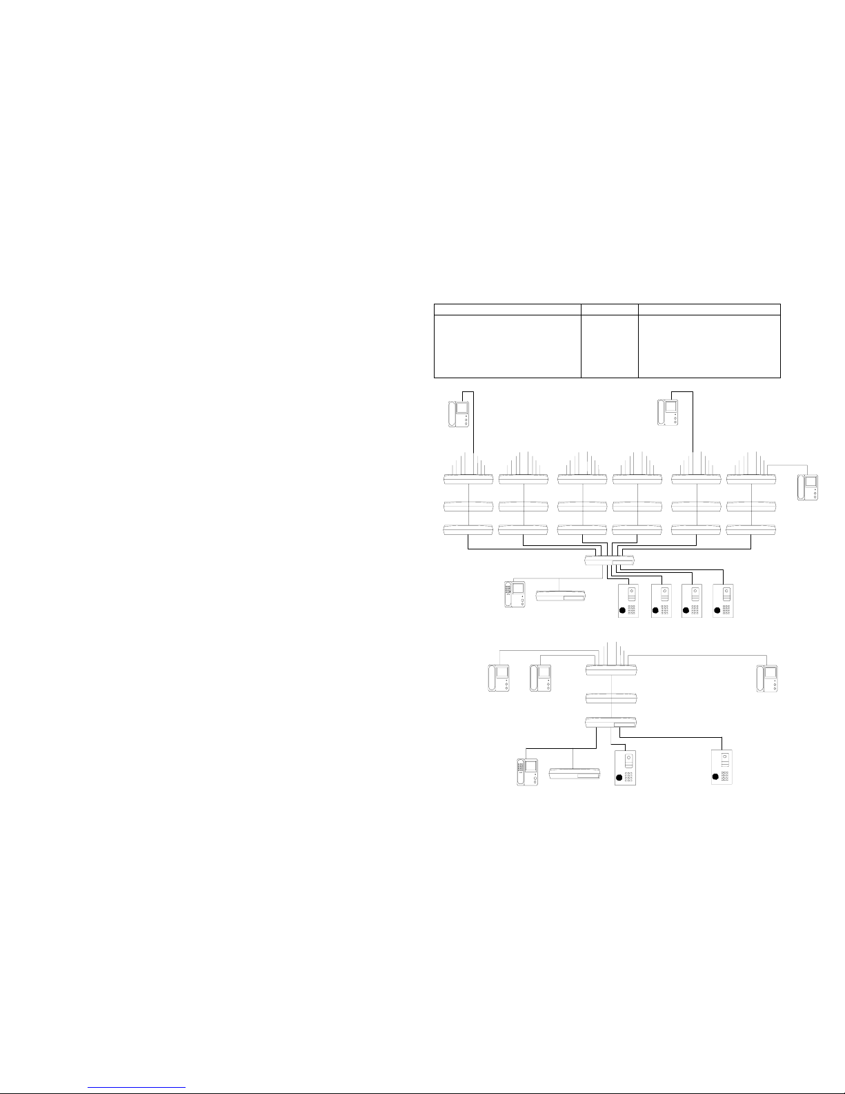
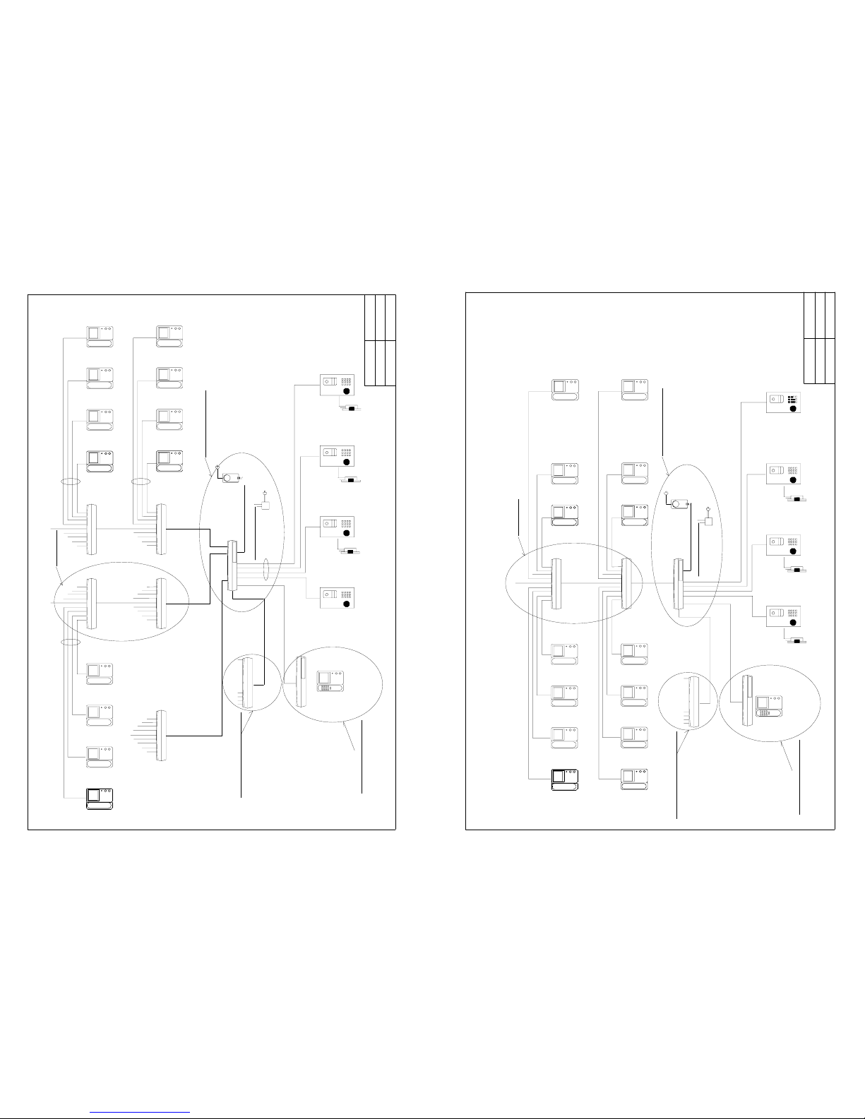
Example of Multiple Riser Configuration
Video Entry Station
Video Entrance Station
Decoder
Main Controller(TMC-750)
Decoder
DecoderDecoder
Video Guard Station Display Unit
DecoderDecoder
DecoderDecoder
DecoderDecoder
DecoderDecoder
Example of Single Riser Configuration
Video Guard Station
Display Unit
Decoder
Video Entrance Station
Video Entrance Station
Main Controller
Decoder
Page 4
Page 4 Page 5
Normal Operation
Making a Call from a Entrance Station to a Handset
The system is ready to use when the Entrance Station displays
on it’s LEDs.
To make a call , enter the related 4 digit unit No. For example;
Unit No. 7 Æ 0007
Unit No. 70 Æ 0070
If an error is made when entering the No. press “✻” key to clear the entry.
Following the 4 digit entry, the Entrance Station extends the call automatically; in this phase,
the melody sounds on both Entrance Station for approximately 30 sec. and the Video Handset
for approximately 5 seconds if not answered. Video screen of Handsets will be on
approximately 30 seconds and display the image from the Entrance Station camera.
If the Handset of the unit called is in use or does not exist, a series of short beep for 7 seconds
will be heard as an error message.
Making a Call from a Entrance Station to the Guard Station
Press ‘#’ button to call guard.
If the guard station is in use or does not exist, a series of short beep for 5 seconds will be heard
as busy tone.
Door opening by the password at the Entrance Station (Optional Extra)
Door can be opened by pressing “✻” and a 4-digit password.
Door opening from the Handsets
During the conversation, the electric door can be activated by pressing the
button on the
handset. A melody will be heard to indicate opening the door on handset. The Entrance Station
displays
during the door open.
Monitoring Entrance area
By pressing button without lifting hand-piece, images from each Entrance Stations can be
display on the screen one after the other. The monitor will be turned off 30 second later
automatically or can be turned off manually by picking up and hanging up the hand piece.
The second call
Thanks to multi-audio channel capability, one Video/Audio and up to 7 audio conversations (in
Standard System 1 additional audio conversations) can be made on a system simultaneously.
(The second call and voice conversation from different Entrance station to different Handset can
be made even if someone uses the system.) Please note there will be no image on the Video
Handset screen for the second call.
Line Busy condition
When all of audio channels are engaged, a series of short beep for 5 seconds will be heard as
busy tone.
With Guard Station (TVG-700 / TAG-700)
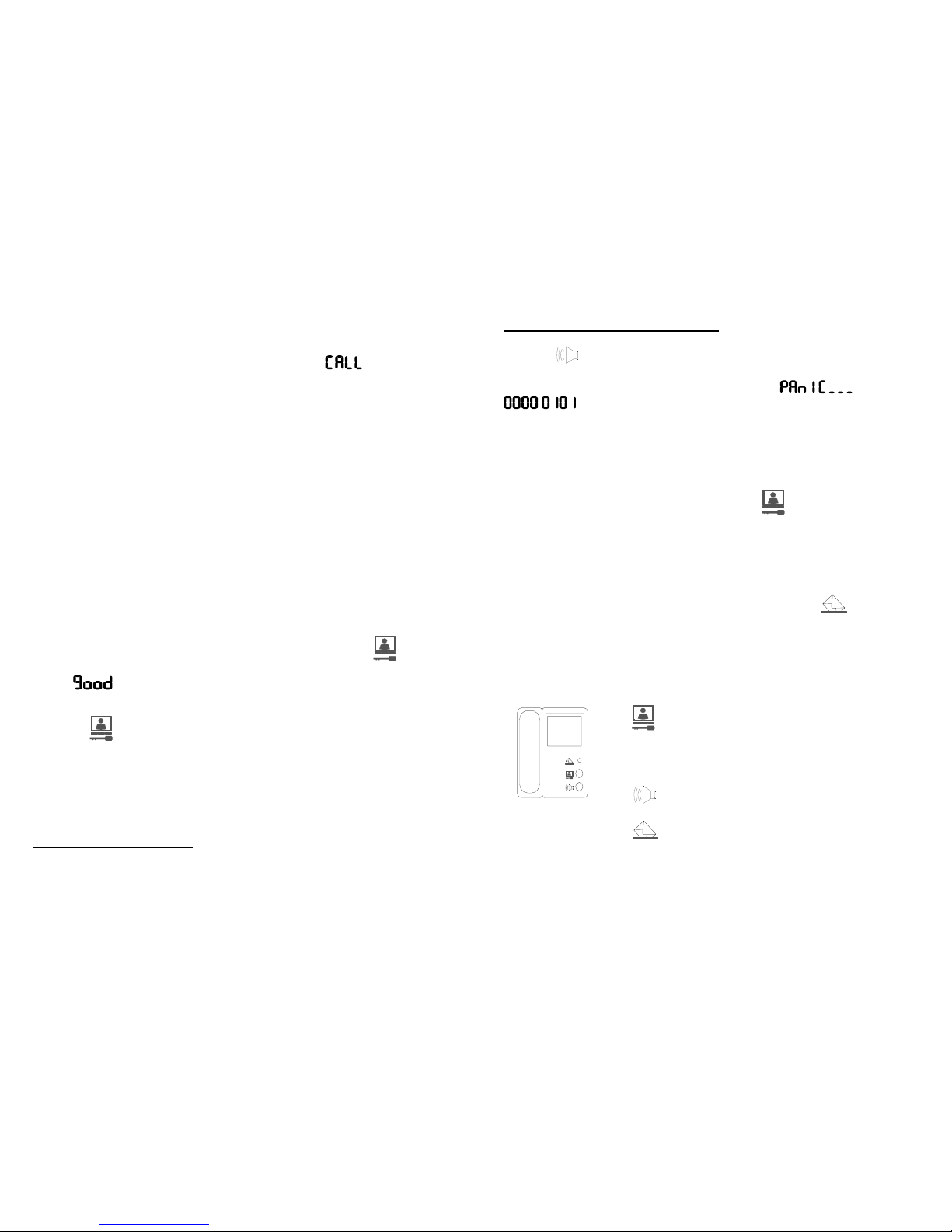
Making and answering a Panic Call to the Guard Station (caretaker station)
Press the button on handset for 2 seconds. Press again to mute beeping
noise.
For example, if a panic call is made from Unit 101 then
ÅÆ
will be displayed on the Display Unit with a loud alarm sound.
Making a call from the Guard station to a Handset
Pick up the hand piece and press unit No in 4 digit.
A melody will be heard if the call is made properly.
Making a call from Handsets to Guard Station
Pick up the hand piece from the handset and press
button. A melody will be
heard if the call is made properly. If the guard station is in use or does not exist, a
series of short beep for 5 seconds will be heard as a busy tone.
Connection a call from a Handset to another Handset through the Guard Station
During conversation with a Handset, press Hook Switch on Guard Handset for 0.5
sec and enter associated unit No. than hang up (Optional Extra).
Operating the Message Indicators from the Guard Station
Guard can make the Message Indicator of Handsets to blink to inform the resident
that the
guard has a message.
To blink the Message Indicator, press “✻” then 4 digit Unit No. then hang up.
To cancel it, press “#” then 4 digit Unit No. then hang up.
TMN-700 Video Handset
button : Monitor/Key
Press to open associated door.
Press to display entrances on monitor.
Pick up the handset and press it to call
Guard
button : Panic
Press 2 Seconds to call Guard Station
LED : Message Indicator
Normally Off, Blinks when guard has a
Message. Automatically off when call the
Guard station by picking up the hand
piece.
Page 5
Page 6 Page 7
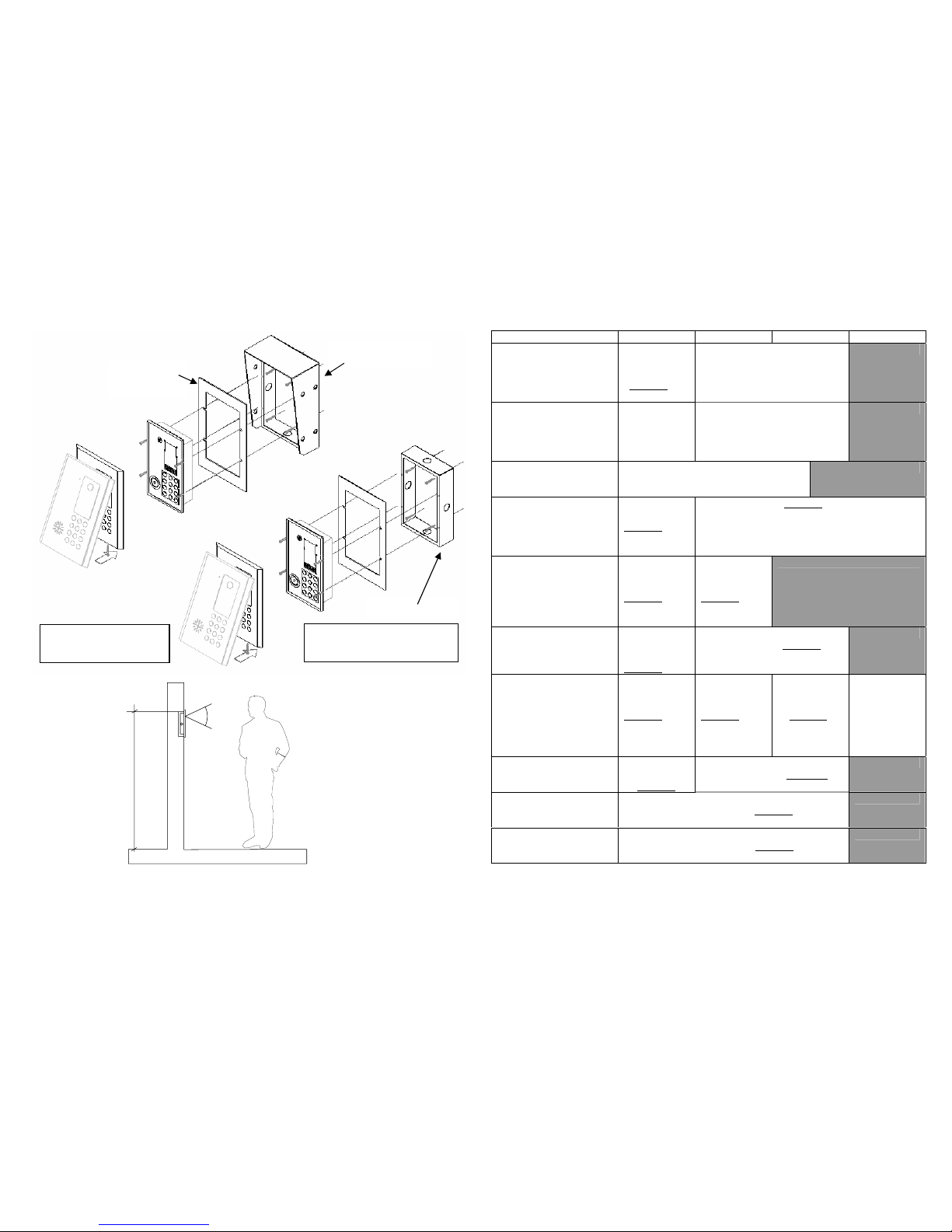
Mounting Entrance Station (with optional Surface Mounting Kit)
1600mm~1650mm
50 ٛ
Camera Angle : Horizontal Angle(Left/Right) : 60 º
º
TVE-700HD Hood
TVE-700SD
Surrounding
Embedding Box
Embedding Box Cutout (mm)
163(W)x256(H)x55(D)
Call Panel Overall (mm)
192(W)x279(H)x12(D)
General Wiring Guide ( for standard 1 channel Video/Audio and 1 channel Audio System)
Distance (Metre) ~25 M ~50 M ~100 M ~300 M
Between:
- Main controller
- Video Entrance Station
(Exclude wires for the
Electric Door Lock)
0.44 mm
2
5core
shielded
0.44 mm
2
2core
0.75 mm
2
2core
RG59 Coax
N/A
Between:
- Electric Door Lock
- Power Supply for
Door Lock via a
Entrance Station
0.75 mm
2
2core
1.5 mm
2
2core
N/A
Between:
- Main controller
- Power Supply
1.5 mm
2
2core
N/A
Between:
- Main controller
- Decoder
0.44 mm
2
7core
shielded
1.5 mm
2
2core
0.44 mm2 6core shielded
RG59 Coax
1.5 mm
2
2core
Between:
- Decoder
- Handset
0.44 mm
2
5core
shielded
0.44 mm
2
3core
shielded
0.75 mm
2
2core
N/A
Between:
- Main controller
- Lift controller
0.44 mm
2
3 core
shielded
0.75 mm
2
3Core shielded
N/A
Between:
- Main controller
- Guard Station
0.44 mm
2
5core
shielded
0.44 mm
2
3core
shielded
0.75 mm
2
2core
0.44 mm2
3core
shielded
0.75 mm
2
2core
RG59 Coax
Audio signal
up to 2 Km
0.44 mm2
2core with
TLI-700 (Long
Distance
Interface)
Between:
- Main controller
- Display Unit
0.44 mm
2
3core
shielded
0.75 mm
2
3core shielded
N/A
Between:
- Main controller
- Master Controller
0.75 mm
2
8core shielded
RG59 Coax
N/A
Between:
- Main controller
- Next Main controller
0.75 mm
2
8core shielded
RG59 Coax
N/A
Cross-section 0.44 mm2 = 14/020 Stranding
Cross-section 0.75 mm
2
= 24/020 Stranding
Cross-section 1.5 mm
2
= 7/067 Stranding
Page 6
Page 8 Page 9
A + B + E
A + B + E A + B + EA + B + E
A + B + E
Location : Security Guard Room
Location : Outside of Lift Motor Room
Location : Main Switch Room
Location : Riser
A : 7 core 14/020 Shielded Cable (0.44mm2)
B : 2 core 14/020 Cable (0.44mm2)
C : 3 Core 14/020 Shielded Cable (0.44mm2)
D : 5 Core 14/020 Shielded Cable (0.44mm2)
E : RG59 Coax Cable
D
D
. . . Upto 6 Risers . . .
Decoder Decoder
Decoder
Multiple Riser Configuration
Main Control Unit
TMC-700
Display Unit
A + C
G 1st ... 16th Floor
B
DOOR LATCH
B
C
D
A + B + E
Power Supply
DOOR LATCH
Decoder
Video Entrance StationVideo Entrance StationVideo Entrance Station
Lift Controller
Video Guard Station
Powersupply for DOOR STRIKE
Video Handset
Decoder
Approved: CHA
Ver.: 1.1
Pjt:
No: t5s4v2
Eos Australia P/L
Date : 15/09/01
A + B + E
A : 7 core 14/020 Shielded Cable (0.44mm2)
B : 2 core 14/020 Cable (0.44mm2)
C : 3 Core 14/020 Shielded Cable (0.44mm2)
D : 5 Core 14/020 Shielded Cable (0.44mm2)
E : RG59 Coax Cable
A + B + E
Location : Security Guard Room
Location : Outside of Lift Motor Room
Location : Main Switch Room
Location : Riser
Video Handset(TMN-700)
. . . .
. . . .
Video Handset(TMN-700) Video Handset(TMN-700)
Power Supply
for Door Strike
DOOR LATCH DOOR LATCH
Video Entrance Station
(TVE-700)
Video Entrance Station
(TVE-700)
Main Control Unit
(TMC-700)
Decoder(TDE-700)
A + B + E
Digital 700 Serise
Single Riser Configuration
Display Unit(TDS-700)
A + C
G 1st ... 16th Floor
A
DOOR LATCH
B
C
D
D
Video Entrance Station
(TVE-700)
Lift Controller(TLC-700)
Video Guard Station(TVG-700)
Video Handset(TMN-700)
Decoder(TDE-700)
Approved: Y.CHA
Ver.: 1.1
Pjt:
No:TS4V2b
Eos Australia Pty Ltd
Date : 15/09/01
Page 7
Page 10 Page 11
To Next Riser
(Series of Decoders)
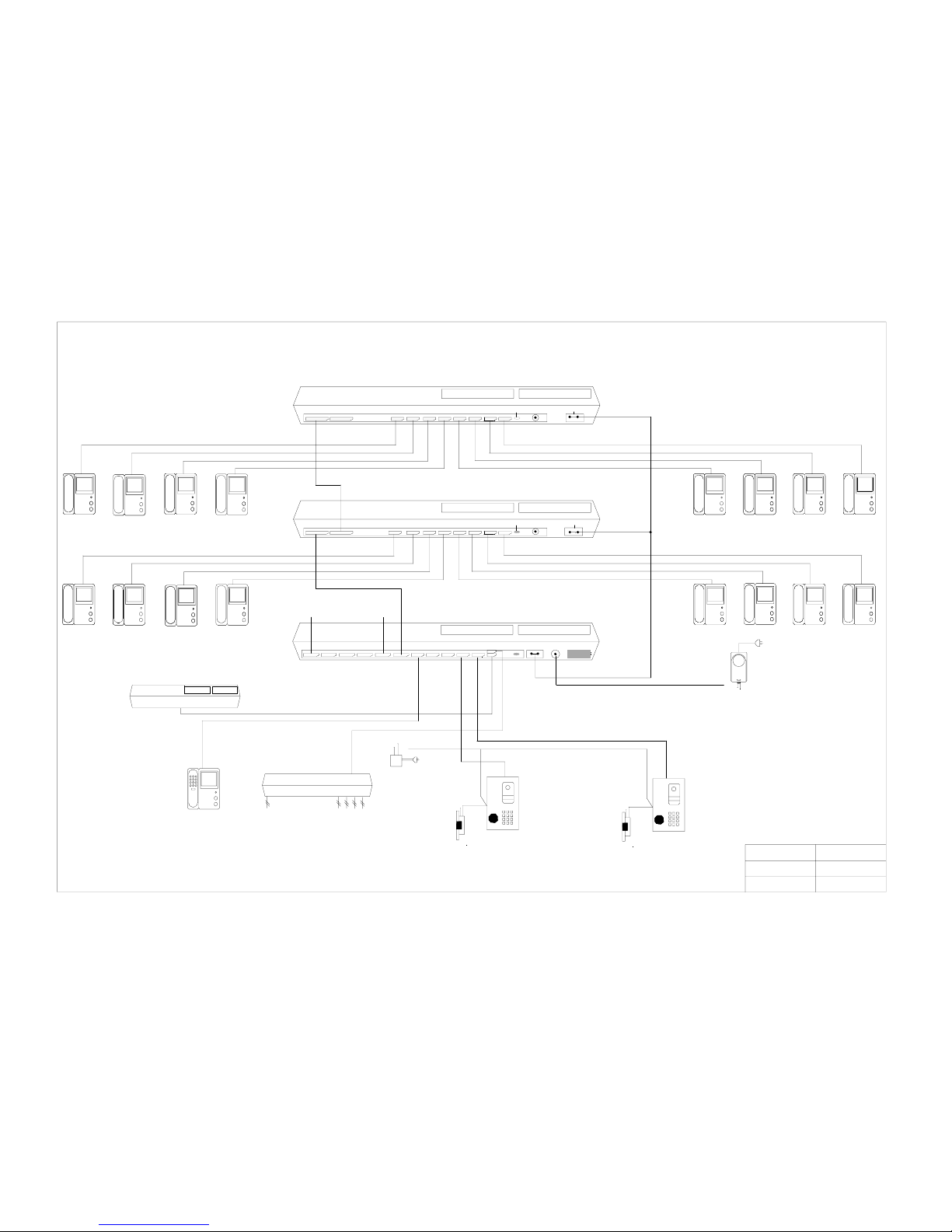
TMC700 (Main Controller)
543 21
3 TVE12TVG
4
TDE-0
TDSTLC DC Output
Power
Indicator
Power
Power Supply (TPS-700)
Digital Video Intercom Connection Diagram
HOUSE 8 7 6 5 4 3 2 1
1st ... 16th Floor
DC PowerJack
TVE700
TVE700 (Video Entrance Station)
DOOR LATCH
DOOR LATCH
TVG700 (Video Guard Station)
TLC700 (Lift Controller)
TDS700 (Display Unit)
TMN700 (Video handset)
Power Exit
Power Exit
DC Adaptor
for DOOR LATCH
Power Indicator
Power Indicator
Bus OutBus In
HOUSE 8 7 6 5 4 3 2 1Bus OutBus In
TDE700 (Decoder)
TDE700 (Decoder)
Approved: Y.CHA
Ver.:
Pjt:
No: ConTs750
Eos Australia P/L
Date : 14/06/01
Page 8
Page 12 Page 13
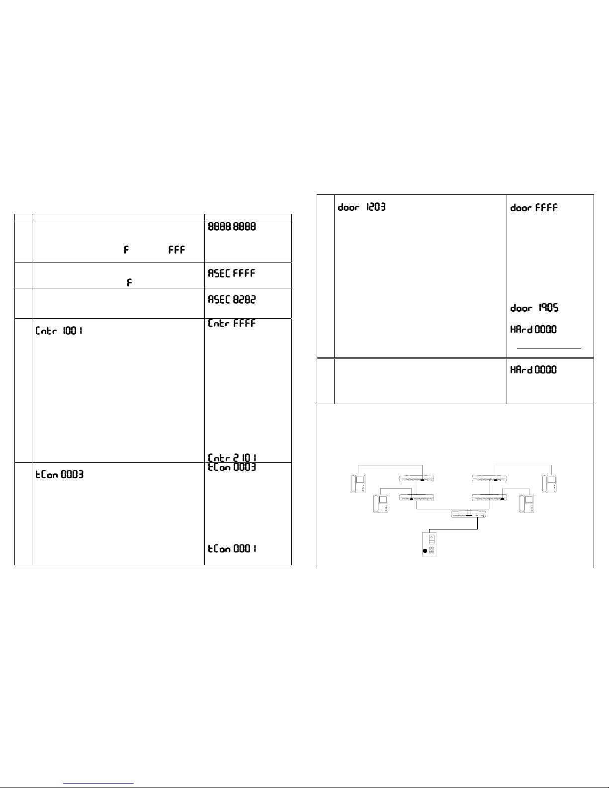
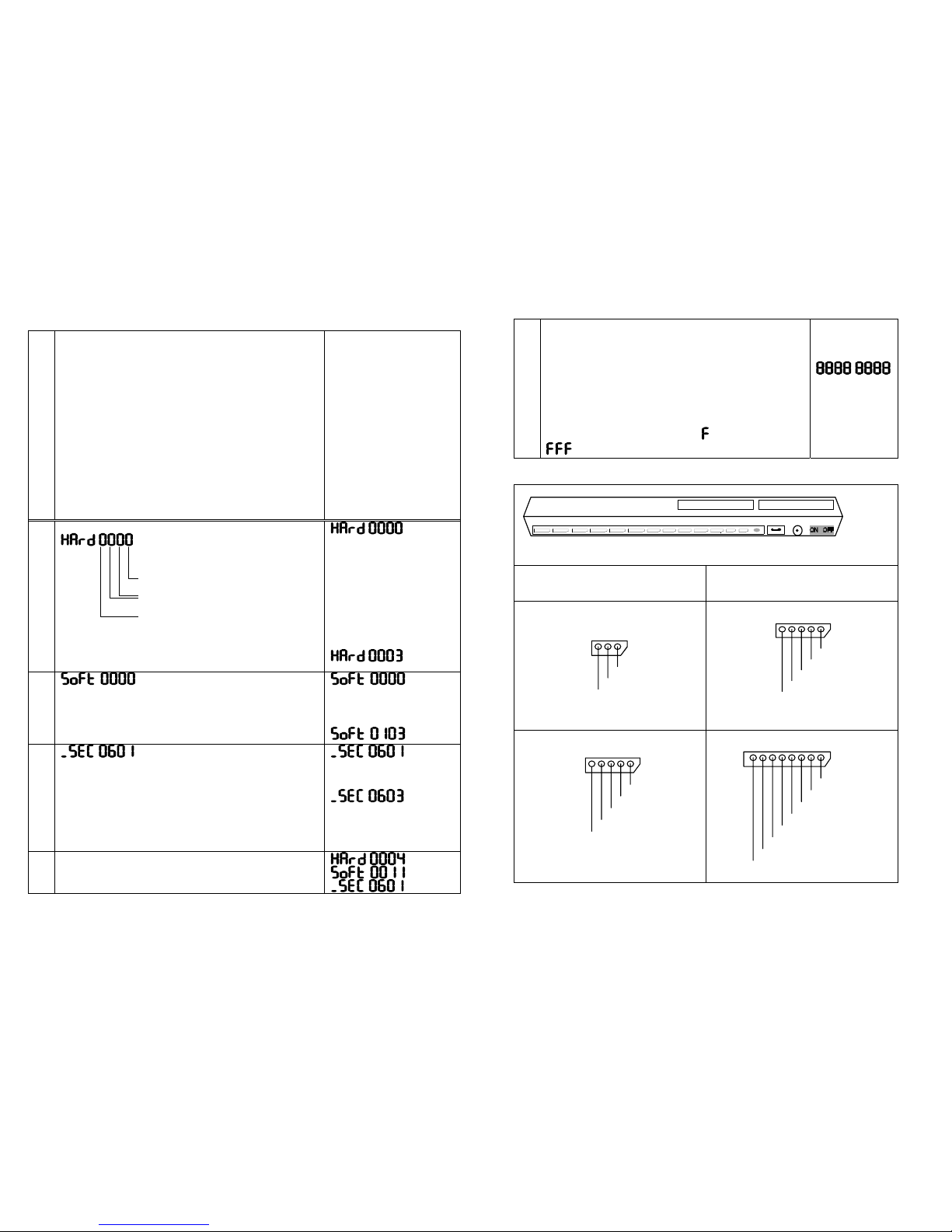
System Programming :
to finish programming press “#” and hang up then turn main power off and on again.
DESCRIPTION DISPLAY on TDS-700
1
Power On
Connect Display Unit and Guard Station to Main Control
Unit.
◈ Main Control Unit will display and change to
after 20sec.
2
Getting Into Programming Mode
Pick up the Guard Station handset and enter “ 9887800 “
◈ Main Control Unit will display .
(or existing value)
3
A Common Door Opener Password (Optional Extra)
Enter a 4digit door opener password (ex. 8282) or press
“ # “ to confirm the existing password.
ASEC NO. is a common door opener code for all units.
4
Setting Up Melody/Guard Station
cdef
➀ : Melody on the Handsets
0 Long Melody / without TPV/TPA-700
1 Long Melody / with TPV/TPA-700
2 Short Melody / without TPV/TPA-700
3 Short Melody / with TPV/TPA-700
d : Unit Number Type
0 Start Unit No. from 0101
1 Start Unit No. from 0001
e : Multiple Main Controller Setting
0 One Main Controller only in the system
1 Multiple Main Control Unit in the system
f : Guard Station Setting
0 Without Guard Station
1 With Guard Station
Enter associated 4 digit No.(ex. 2101) and press “#”
key or just press “#” key to accept existing entry.
(or existing value)
5
Communication Time Setting between Units
│ │└─└ d Internal communication time limit
│ │ (minute). Default is 3 minutes
└─└─── c
Main Controller ID No.(00~49)
When there is only one Main controller enter “00”
by pressing “#”key.
(Please skip this step if there is no Master Station by
pressing “#”key)
Enter associated 4 digit No.(ex. 0001) and press “#”
key or just press “#” key to accept existing entry.
(or existing value)
6
Door/Lift Control Unit Time Setting
cdef
c
: Activating Delay Time(sec.) on Lift Control Unit
(Unit Value 2Sec, Max 19 Sec)
d : Relay Activating Time(sec.) on Lift Control Unit
(Unit Value 20Sec, Max 190 Sec)
e : Total number of Video Entrance Station
connected
to the Main Controller
0 : 1 Video entrance
1 : 2 Video entrances
2 : 3 Video entrances
3 : 4 Video entrances
f : Door Opener Activating Time(sec.)
Enter associated 4 digit No.(ex 1905) and press
“#” key or just press “#” key to accept existing
entry.
◈ End of system setting
7
Start Unit No. Setting
Please read following example to understand basic
programming concept.
Unit No. Programming Example
ex 3.
Hard No of this Handset is "0102
"
1st Riser Port (#0)
2nd Decoder (#1)
3rd Socket (#02)
ex 2.
Hard No of this Handset is "1102"
2nd Riser Port (#1)
2nd Decoder (#1)
3rd Socket (#02)
ex 1.
If Handset in Unit No.27(0027)
is connected to
6th Socket (#05) on
1st Decoder (#0) of
2nd Riser Port (#1)
the Soft No. on Hard No "1005"
"
"
1st Decoder
(Decoder #0)
2nd Decoder
(Decoder #1)
Video Entrance Station
Main Controller
(#02)
(#05)
(#02)
(#00)
ex 4.
If Handset in Unit No.1(0001)
is connected to
1st Socket (#00) on
1st Decoder (#0) of
1st Riser Port (#0)
the Soft No. on Hard No "0000"
will be "0001".
TDE1 0
Page 9
Page 14 Page 15
Unit No. Programming Continue.
8
Riser Memory Format –
IMPORTANT!!
On every 6 Riser output, the first Hard No. on next
available Decoder (Next free Decoder) MUST be
programmed by Soft No “9999”.
Soft No. “9999” stands for “End of Riser” for the
system software.
ex. When there are 2 Decoders on Riser #0,
Æ ‘Hard 0020’ MUST programmed by ‘Soft 9999’.
When there are 8 Decoders on Riser #1,
Æ ‘Hard 1900’ MUST programmed by ‘Soft 9999’.
When there is no Decoders connected to
Riser #2, #3, #4, #5.
Æ ‘Hard 2000’ , ‘3000, ‘4000, ‘5000’
MUST programmed as ‘Soft 9999’.
N.B : HARD No 6000,6100,6200,6300 must not FFFF
see Page 19
At leaset one Soft No. on
each Riser Port MUST
programmed as 9999
9
Unit No. Setting
Enter 4 digit Hard No (ex. 0003) and press “#” key or just
press “#” key to accept existing No.
10
Soft Number : The No. shall be entered on Keypads at
the Entrance Station (eg. Unit No. or Room No.)
Enter associated 4 digit Soft No(ex. 0103) and press
“#” key or just press “#” key to accept existing soft
No.
11
Level No. for Lift Controller (0600~0615)
Associated relay contact on the Lift Controller will be
closed when door open button is pressed on a handset.
Enter associated 4 digit Level No(ex. 03) and press
“#” key or just press “#” key to accept existing Level
No.
The first two digit must be “06”.
12 Repeat step “8”, “9”, ”10” for next unit.
Depending on the physical
port(socket) location in the system
c
Socket No. on Decoder (0~9)
d Decoder No on the
System (00~49)
e Riser No on the Main
Controller TMC-700 (0~5)
13 To finish programming press “#” and hang up the
handset.
Turn the main power Off and On again and wait about 20
seconds for normal operation mode with
new programming setup.
Press reset button on the Display Unit to reset
7-Segment LEDs.
◈ Main Control Unit will display
and change to
20sec. Later.
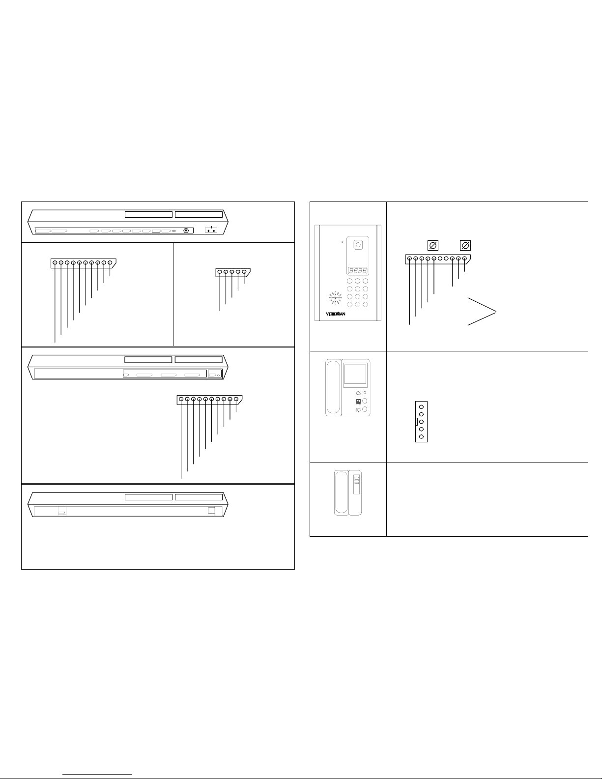
System Components
TMC-700 Main Controller
Power
Power
Indicator
DC OutputTDSTLCTDE-0 4TVG 2 TVE13
DC Power
Jack
12345
Dimension 310mm(W) x 56mm(H) x 180mm(D)
DC Output
Connect to the Power IN connector
on the Decoders
DC POWER JACK
Connect to the TPS-700 power supply
(centre positive DC24V)
TDS Port : to Display Unit
TLC Port : to Lift Controller
add.06~07
VDD(red)
GND(black)
DATA
TVE4, 3, 2, 1 Ports : add. 7000~7003
to Video Entrance Station
VDD(red)
GND(black)
AUDIO(blue)
DATA(white)
VIDEO(yellow)
TVE4 and TVE3 can be connected to
AUX phone (TAP-700).
TVG port : port address: 7004
to Guard Station
VDD(red)
GND(black)
AUDIO(grey)
DATA(white)
VIDEO(yellow)
TDE 0, 1, 2, 3, 4, 5 port : to Decoder
6Ports for multiple Riser configuration
S VDD(red)
GND(black)
RX Data(brown)
TX Data(violet)
Audio 0(orange)
Audio 1(blue)
Audio for Guard(green)
Video(yellow)
Page 10
Page 16 Page 17
TDE-700 Decoder
HOUSE 8 7 6 5 4 3 2 1
Bus In Bus Out
Power Indicator
Power Exit
Dimension 310mm(W) x 56mm(H) x 180mm(D)
TDE Port : to Main Controller or Next
Decoder’s Bus In ÅÆ Bus Out
S VDD(red)
GND(black)
RX Data(brown)
TX Data(purple)
Audio 0(orange)
Audio 1(blue)
Audio for Guard(green)
Not in Use
Not in Use
Video(yellow or Coax)
House 8 ~1 Ports : to Handsets
VDD(red)
GND(black)
AUDIO(blue)
DATA(white)
VIDEO(yellow)
TLC-700 Lift Controller
TLC5~110~615~1116
Dimension 310mm(W) x 56mm(H) x 180mm(D)
5~1 : Associated output for Level 1~5
10~6 :Associated output for Level 10~6
15~11 :Associated output for Level 15~11
16 :Associated output for Level 16 Level 0
Level 0
These outputs are ‘dry contact’(no voltage) only. Level 1
Level 1
TLC Port : Connect to TLC Port on Main Controller Level 2
Level 2
Level 3
Level 3
Level 4
Level 4
TDS-700 Display Unit
TDS
Reset
Dimension 310mm(W) x 180mm(D) x 56mm(H)
Displays the unit No. when residents call guard station.
An alarm sounds and displays unit No. when a panic button is pressed.
Press RESET button to cancel the alarm sound and reset the display.
Displays all status and entry in programming mode.
TDS Port : Connect to TDS Port on the Main Controller
1 2 3
4 5 6
7 8 9
0 #
*
TVE-700 Video Entrance Station
# button : Reset / Door open password entry mode
button : Guard Call
Microphone Adj. Speaker Volume Adjustment
N.B: Door Lock contacts are
A ‘voltage free dry contact’.
Door Lock:Normally Close(Orange)
Door Lock: Normally Open(Purple)
Door Lock: Common(Green)
Video Output(Yellow)
Data(white)
Audio(blue) to Main Controller
GN(black) (TMC-700) TVE port
S VDD(red)
Dimension
Overall 192mm(W) x 279mm(H) x 12mm(D)
Cutout 163mm(W) x 256mm(H) x 55mm(D)
TMN-700 Video Handset
Monitor/Key button : Press to open associated door.
Press to display entrances on monitor.
Panic button : Press 2 Seconds to call Guard Station
Red LED: : Normally Off, Blinks when guard has a
Message. Automatically off when calls the
Guard station by picking up the hand piece.
--- VDD(red)
--- GND(black)
--- AUDIO(blue)
--- DATA(white)
--- VIDEO(yellow)
1R,2W, 3Y,4B terminal to Private Entrance Station(TPV-700)
Dimension 182mm(W) x 216mm(H) x 52mm(D)
THS-700 Audio Handset
Out Door button : Press to talk to the Private Entrance Station
Panic button : Press 2 Seconds to call Guard Station
Message LED : Normally Off, Blinks when guard has a
Message. Automatically off when calls the
Guard station by picking up the hand piece.
Door LED : Will be on when Door Button is pressed.
Connector signals are same as Video Handset without
Video Signal.
Dimension 107mm(W) x 218mm(H) x 70mm(D)
Page 11
Page 18 Page 19
+
TMN-750
THS-750
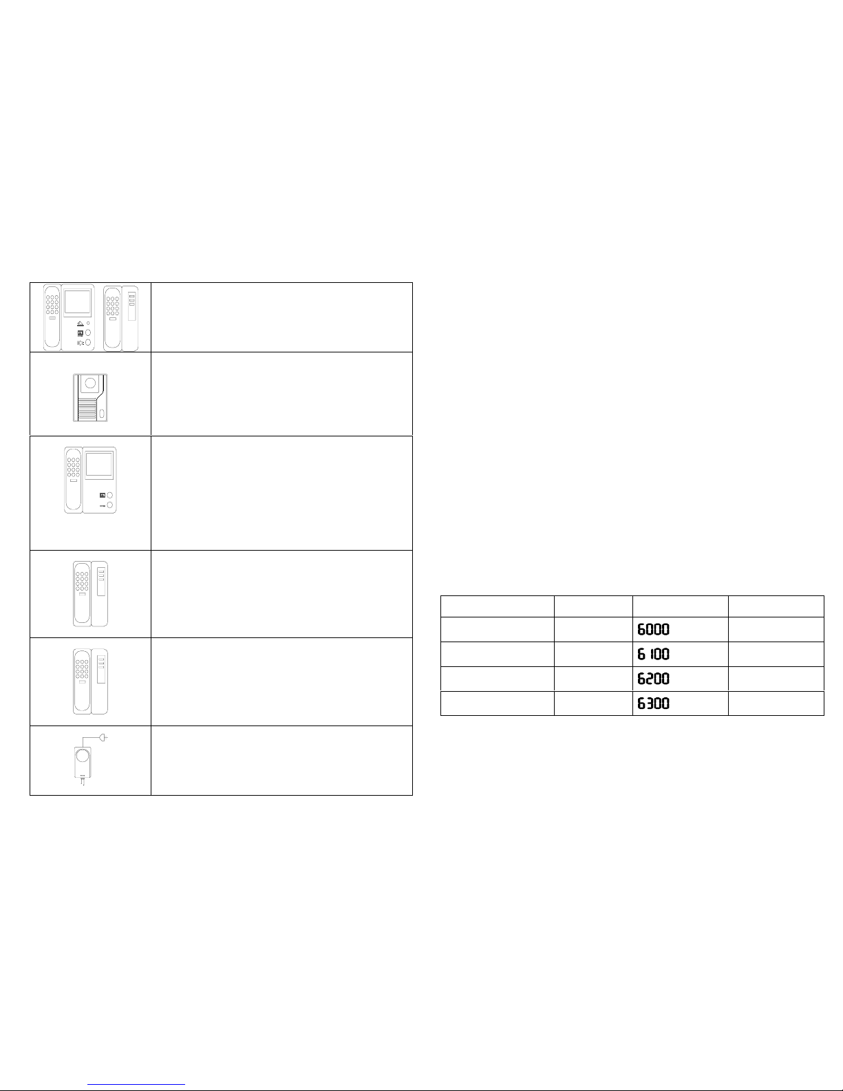
Same as TMN-700 and THS-700 with a keypad on hand piece
for making a direct call to another Handsets.
TPV-700 / Private Entrance Station Video
Video/Audio call station for private entrances (court yard entry
or unit entry)
1R,2W ,3Y,4B terminal to the Handset
TPA-710 is identical to TPV-700 but with no Camera.
Dimension 97mm(W) x 128mm(H) x 55mm(D)
TVG-700 Video Guard Station
Monitor button : Press to display entrances on monitor
Key button : Press to open associated door.
Numeric Key Pad: Dial 4 digit unit No. to call the unit or turn on
the Message Indicator LED on the Handset.
N.B: To connect a handset to the other during conversation,
press Hook Switch for 0.5 sec and enter associated unit
no. than hang up.
Dimension 182mm(W) x 216mm(H) x 52mm(D)
TAG-700
Same as Video Guard Station but with no Screen.
Dimension 107mm(W) x 218mm(H) x 70mm(D)
TAP-700 Auxiliary phone
Additional auxiliary phones can be attached to the Main
Controller to communicate between common area (swimming
pool, gym) and any handsets or guard station.
Dimension 107mm(W) x 218mm(H) x 70mm(D)
TPS-24 Power Supply
24V DC 2.0Amp SMPS power supply
Dimension 84mm(W) x 146mm(H) x 48mm(D)
Special Extras
Long distance interface unit for the Guard Station (TLI-700)
When guard station is located far away (up to 2 Km) this transmitter/receiver can be
used for audio communication.
Fire Stair Call Station (TGI-700)
Audio only calls station to communicate with the guard station.
Full fireproof design for installing in fire stairs.
Port Expander (TEX-700)
Interface with up to 8 Entrance Stations or Aux Phones and connect to EXP port on
Main Controllers.
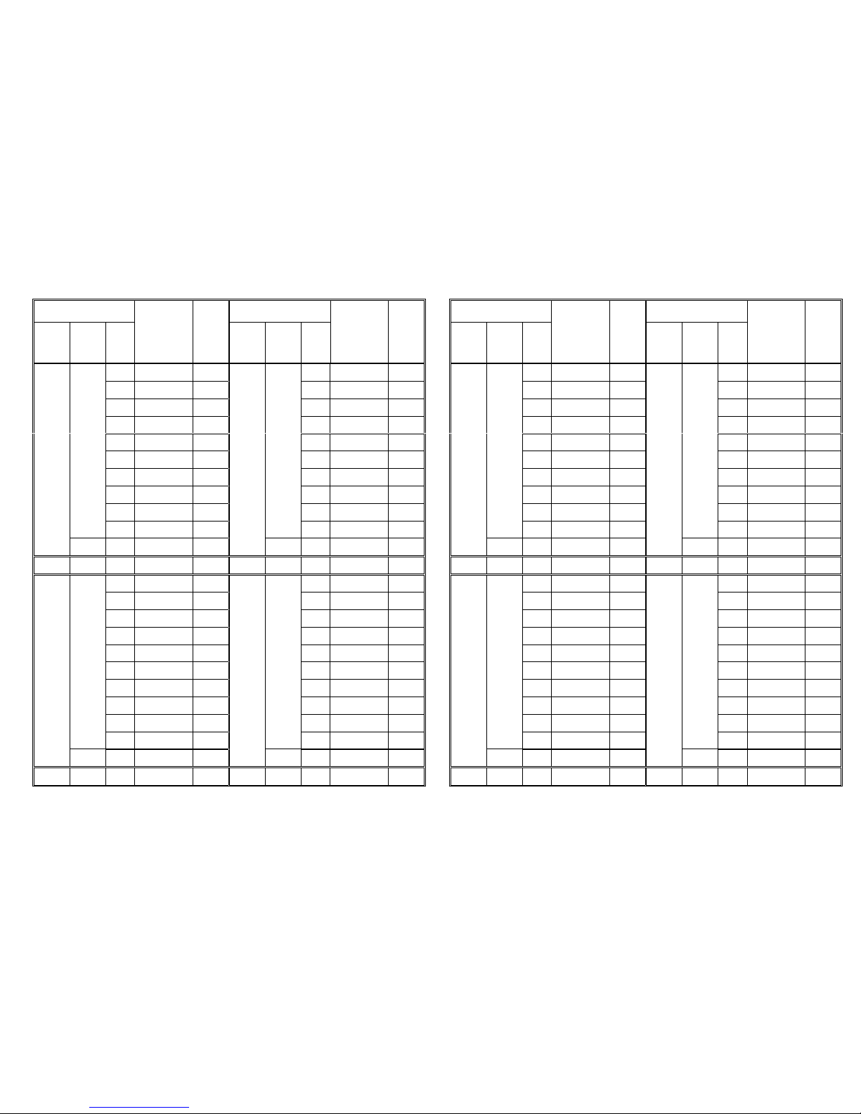
Project Data Note
Please use the following pages for your own project reference
Project : Site Address:
Total No of Unit : Total No of Entrance Station:
Call Restriction Programming :
The Soft No. on Hard No 6000,6100,6200,6300 must be programmed properly.
Should not be left as it’s default value ‘FFFF’
Call Panel TVE-700 Riser Port
TDE # 0~5
Hard No. Soft No.
TVE #1 Port
TVE #2 Port
TVE #3 Port
TVE #4 Port
Example
1. Call Panel attached to TVE #1 port need to communicate all of the Units.
Eg all if the Risers.
2. Call Panel on TVE #2 port need to communicate only the units attached to Riser #0, 1, & 3.
Hard No 6000 Æ Soft No.9999
Hard No 6100 Æ Soft No.0139
Page 12
Page 20 Page 21
Hard No.
Decoder Socket No.
Hard No.
Decoder Socket No.
Riser
No.
0~5
Dec.
No.
0~49
Plug
No.
Soft No.
(Unit or
Room No.)
Floor
No.
_SEC
Riser
No.
0~5
Dec.
No.
0~49
Plug
No.
Soft No.
(Unit or
Room No.)
Floor
No.
_SEC
0
06 0
06
1
06 1
06
2
06 2
06
3
06 3
06
4
06 4
06
5
06 5
06
6
06 6
06
7
06 7
06
8
06 8
06
9
06
9
06
0
06 0
06
1
06 1
06
2
06 2
06
3
06 3
06
4
06 4
06
5
06 5
06
6
06 6
06
7
06 7
06
8
06 8
06
9
06
9
06
Hard No.
Decoder Socket No.
Hard No.
Decoder Socket No.
Riser
No.
0~5
Dec.
No.
0~49
Plug
No.
Soft No.
(Unit or
Room No.)
Floor
No.
_SEC
Riser
No.
0~5
Dec.
No.
0~49
Plug
No.
Soft No.
(Unit or
Room No.)
Floor
No.
_SEC
0
06 0
06
1
06 1
06
2
06 2
06
3
06 3
06
4
06 4
06
5
06 5
06
6
06 6
06
7
06 7
06
8
06 8
06
9
06
9
06
0
06 0
06
1
06 1
06
2
06 2
06
3
06 3
06
4
06 4
06
5
06 5
06
6
06 6
06
7
06 7
06
8
06 8
06
9
06
9
06
 Loading...