

Videology 45M10-1, 45M15, 45M20-1, 45M17 User Manual
Doc # INS-45MX-Series
Issue Date: 9/28/2011
Revision: E
Page 1 of 26
Videology Imaging Solutions, Inc. USA
Videology Imaging Solutions, B.V. Europe
37M Lark Industrial Parkway
Greenville, RI 02828
Tel: 401-949-5332
Fax: 401-949-5276
www.videologyinc.com
Neutronenlaan 4
NL-5405 NH Uden, Netherlands
Tel: +31 (0) 413-256261
Fax: +31 (0) 413-251712
www.videology.nl
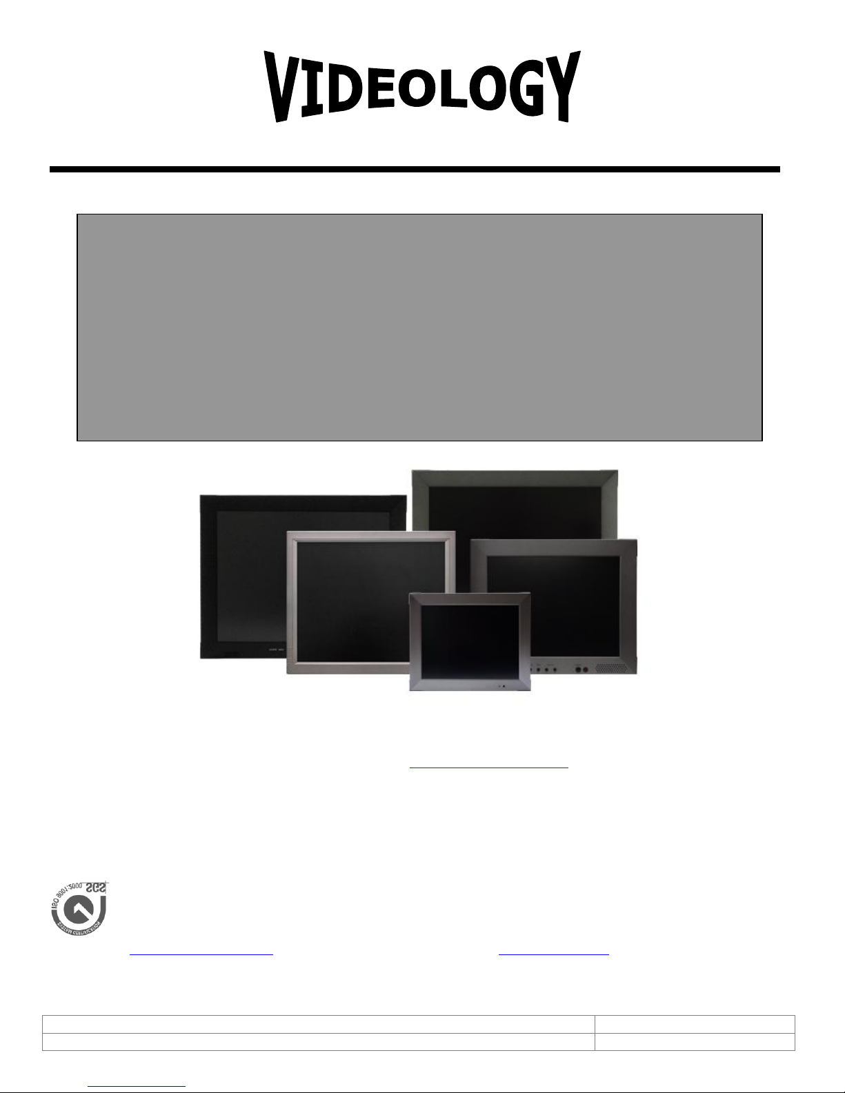
User Manual for LCD Monitors
45M10-1 10.4” TFT
45M15 15” TFT
45M17 17” TFT
45M20-1 20” TFT
IMAGING SOLUTIONS INC.
Original Equipment Manufacturer
Prior to Using This Document: Videology reserves the right to modify the information in this
document as necessary and without notice. It is the user’s responsibility to be certain they possess the
most recent version of this document by going to www.videologyinc.com, searching for the model
number, and comparing revision letters on the respective document, located in the document’s footer.
For technical assistance with this product, please contact the supplier from whom the product was
purchased.

Doc # INS-45MX-Series
Issue Date: 9/28/2011
Revision: E
Page 2 of 26
Table of Contents
1. Document History .................................................................................................................... 3
2. Warning ................................................................................................................................. 3
3. Precautions ............................................................................................................................. 3
3.1. Safety ............................................................................................................................. 3
3.2. Installation ....................................................................................................................... 4
3.3. Cleaning .......................................................................................................................... 4
4. Federal Communications Commission (FCC) Statement ................................................................ 4
5. Features ................................................................................................................................. 5
5.1. 45M10-1 10.4” TFT ........................................................................................................... 5
5.2. 45M15 15” TFT ................................................................................................................. 5
5.3. 45M17 17” TFT ................................................................................................................. 5
5.4. 45M20-1 20” TFT .............................................................................................................. 5
6. Operating Instructions ............................................................................................................. 6
6.1. Control for 10”, 15” and 20” LCDs ....................................................................................... 6
6.2. Control for 17” LCD ........................................................................................................... 7
7. Connectors ............................................................................................................................. 8
7.1. 10.4” Monitor Back Panel ................................................................................................... 8
7.2. 17” Monitor Back Panel ...................................................................................................... 9
7.3. 15”, 20” Monitor Back Panel ............................................................................................. 10
8. OSD Architecture ................................................................................................................... 11
8.1. Video Function 10”, 15”, 20” ............................................................................................ 11
8.2. Video Function (PC Mode Only) 10”, 15”, 20” ..................................................................... 12
8.3. OSD Functions for 17” (45M17) ....................................................................................... 13
8.3.1. Source .................................................................................................................... 13
8.3.2. Item (Hot key, simple operation) ............................................................................... 13
8.3.3. OSD Menu ............................................................................................................... 13
8.4. Audio Function (10”, 15” 20”) ........................................................................................... 18
9. LCD Monitor Mounting Guide ................................................................................................... 19
9.1. Desktop Mount ............................................................................................................... 19
9.2. Wall / VESA mount .......................................................................................................... 19
10. Device Connectors .............................................................................................................. 20
11. Specifications .................................................................................................................... 22
12. Appendixes........................................................................................................................ 23
12.1. Troubleshooting .......................................................................................................... 23
12.2. Package Contents ........................................................................................................ 23
13. Remote Control .................................................................................................................. 24
13.1. Remote Control For 10”, 15”, 20” LCDs .......................................................................... 24
13.2. Remote Control for 17” LCD .......................................................................................... 25
14. Contact Information ........................................................................................................... 26
Doc # INS-45MX-Series
Issue Date: 9/28/2011
Revision: E
Page 3 of 26
1. Document History
Revision
Issue Date
Reason
CN#
Rev A
09-21-2007
Initial release
05-0688
Rev B
07-24-2006
Added 45M10-1, removed 45M10
06-0153
Rev C
12-07-2007
Added 45M20
07-0228
Rev D
06/29/2010
Added 45M20DX
10-0102
Rev E
08/17/2011
New model for 17” monitor, all sections updated, removed
45M20DX
11-0101
The exclamation point within an equilateral triangle is intended to alert the
user to the presence of important operating and maintenance (servicing)
instructions in the literature accompanying the product.
The lightning flash with arrowhead symbol, within an equilateral triangle, is
intended to alert the user to the presence of non-insulated dangerous voltage
within the product's enclosure that may be of sufficient magnitude to
constitute a risk of electric shock to persons.
2. Warning
TO REDUCE THE RISK OF FIRE OR ELECTRIC SHOCK:
DO NOT EXPOSE THIS PRODUCT TO RAIN OR MOISTURE.
DO NOT INSERT ANY METALLIC OBJECT THROUGH VENTILATION GRILLS.
CAUTION:
Explanation of Graphical Symbols
3. Precautions
3.1. Safety
Should any liquid or solid object fall into the cabinet, unplug the unit and have it checked by the qualified
personnel before operating it any further. Unplug the unit from the wall outlet if it is not going to be used
for several days or more. To disconnect the cord, pull it out by the plug. Never pull the cord itself. Allow
adequate air circulation to prevent internal heat built-up. Do not place the unit on surfaces (rugs,
blankets, etc.) or near materials (curtains, draperies) that may block the ventilation holes.

Doc # INS-45MX-Series
Issue Date: 9/28/2011
Revision: E
Page 4 of 26
3.2. Installation
This device complies with Part 15 FCC Rules. Operation is subject to the
following two conditions:
(1) This device may not cause harmful interference.
(2) This device must accept any interference received including interference
that may cause undesired performance.
Do not install the unit in an extremely hot or humid place or in a place subject to excessive dust or
mechanical vibration. The unit is not designed to be waterproof. Exposure to rain or water may damage
the unit.
3.3. Cleaning
Clean the unit with a slightly damp soft cloth. Use a mild household detergent. Never use strong solvents
such as thinner or benzine as they might damage the finish of the unit.
Retain the original carton and packing materials for safe transport of this unit in the future.
4. Federal Communications Commission (FCC) Statement
This Equipment has been tested and found to comply with the limits for a Class B digital device, pursuant
to Part 15 of the FCC rules. These limits are designed to provide reasonable protection against harmful
interference in a residential installation. This equipment generates, uses and can radiate radio frequency
energy and, if not installed and used in accordance with the instructions, may cause harmful interference
to radio communications. However, there is no guarantee that interference will not occur in a particular
installation. If this equipment does cause harmful interference to radio or television reception, which can
be determined by turning the equipment off and on, the user is encouraged to try to correct the
interference by one or more of the following measures:
Reorient or relocate the receiving antenna.
Increase the separation between the equipment and receiver.
Connect the equipment into an outlet on a circuit different from that to which the receiver is
connected.
Consult the dealer or an experienced radio/TV technician for help.
You are cautioned that changes or modifications not expressly approved by that party responsible for
compliance could void your authority to operate the equipment.

Doc # INS-45MX-Series
Issue Date: 9/28/2011
Revision: E
Page 5 of 26
5. Features
5.1. 45M10-1 10.4” TFT
NTSC/ PAL Auto Selectable
IR Remote Control Enabled
Inputs/Outputs: 2 BNC Composite Video, S-Video, 2CH Audio (RCA) & PC IN
Auto Termination 75 Ohms
VESA Standard Bracket & Desktop Mount
Easy OSD Menu User Interface
Wall Mountable
5.2. 45M15 15” TFT
NTSC/ PAL Auto Selectable
2/4 H Adaptive Comb Filter For Y/C Separation
IR Remote Control Enabled
Inputs/Outputs: 2 BNC Composite Video, S-Video, 2CH Audio (RCA) & PC IN
Auto Termination 75 Ohms
VESA Standard Bracket & Desktop Mount
Easy OSD Menu User Interface
Wall Mountable
5.3. 45M17 17” TFT
NTSC/ PAL Auto Selectable
Ultra High Resolution (1280 x 1024 Pixels)
IR Remote Control Enabled
Inputs/Outputs: 1 BNC Composite Video, S-Video, 1CH Audio (RCA) & PC IN
Auto Termination 75 Ohms
VESA Standard Bracket & Desktop Mount
Easy OSD Menu User Interface
Wall Mountable
3D Comb Filter
3D De-interlace technology
PIP Control (only in PC/Video Mode)
Built-in Speakers
5.4. 45M20-1 20” TFT
NTSC/PAL Auto Selectable
450 cd/m2 Brightness
IR Remote Control Enabled
Inputs/Outputs: 2 BNC Composite Video, S-Video, 2CH Audio (RCA) & PC IN
Auto Termination 75 Ohms
VESA Standard Bracket & Desktop Mount
Easy OSD Menu User Interface
Wall Mountable
Doc # INS-45MX-Series
Issue Date: 9/28/2011
Revision: E
Page 6 of 26
6. Operating Instructions
1
2
3
4
5
6
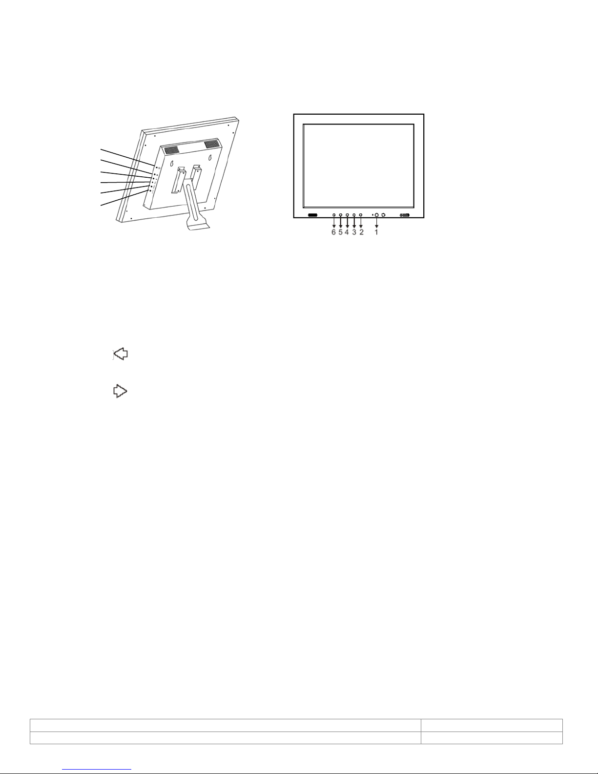
Figure 1. 10.4” LCD Monitor
Figure 2. 15”, 20” LCD Monitors
6.1. Control for 10”, 15” and 20” LCDs
1. Power
Monitor power ON / OFF. At OFF mode, monitor will be at standby status
Green Light -- Power On
Red Light -- Standby mode
2. Adjust
Increase the value on the OSD menu or turn ON / OFF function
3. Adjust
Decrease the value on the OSD menu or turn ON / OFF function
4. Item
Chose sub menu from Audio / Video / Image
Press again to enter selected option
5. Menu
OSD menu ON / OFF control
6. Source
Select input signal from AV1, AV2, S-Video or PC
Note: Push “menu” and “up” to put into key-lock mode, and push again to unlock.
Doc # INS-45MX-Series
Issue Date: 9/28/2011
Revision: E
Page 7 of 26
6.2. Control for 17” LCD
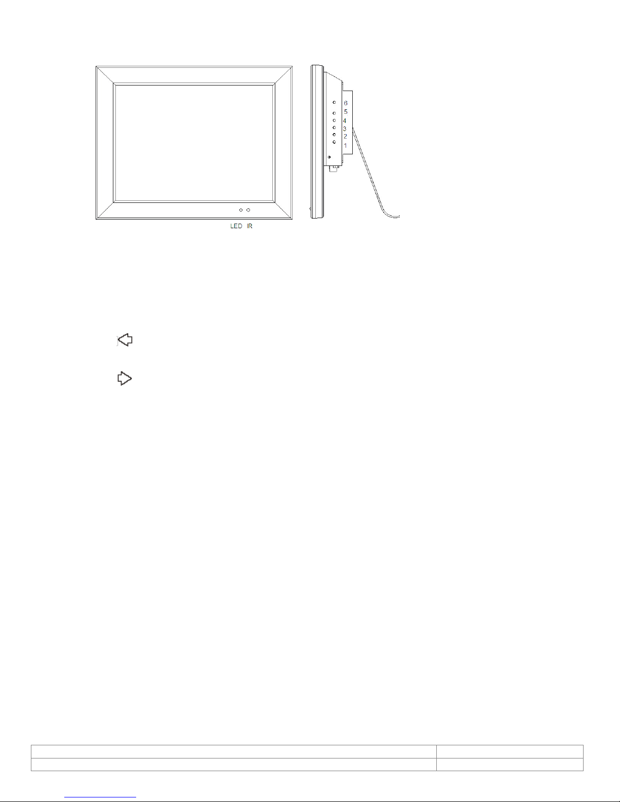
Figure 3. 17” LCD Monitor
1. Power
Monitor power ON / OFF. At OFF mode, monitor will be at standby status
Green Light -- Power On
Red Light -- Standby mode
2. Adjust
Increase the value on the OSD menu or turn ON / OFF function
3. Adjust
Decrease the value on the OSD menu or turn ON / OFF function
4. Item/Select
Choose sub menu Hot key selection for Brightness/ Contrast/ Backlight/ Sharpness/ Hue/ Color/
Volume
Press again to enter selected option
5. Menu/Function
OSD menu ON / OFF control
6. Source
SDE: Select input signal from AV1, S-Video or PC.
SHDE: Select input signal from AV1, AV2, S-Video, PC, HD.
Used as "Return/Exit" function in OSD menu
***Push “Menu” and “Up” into key-lock mode, and push again into unlock.***

Doc # INS-45MX-Series
Issue Date: 9/28/2011
Revision: E
Page 8 of 26
7. Connectors
Note: Audio out is muted until video is present
Audio Connections
Audio 1
Audio 2
PC √
AV1 √
AV2 √
S-Video √
1 AUDIO 2 OUT
Audio looping outputs for AUDIO 2
2 AUDIO 2 IN
Stereo Audio Signal Input, this input is for
PC or Av2 or S-Video (refer to note below)
3 AUDIO 1 OUT
Audio looping outputs for AUDIO 1
4 AUDIO 1 IN
Stereo Audio Signal Input, this input is for
Av1 (refer to note below)
5 Y/C IN (S-Video)
Y/C separated signal input
6 VIDEO 2 OUT
Video looping output for VIDEO 2
7 VIDEO 2 IN
Composite signal Input for VIDEO 2
8 VIDEO 1 OUT
Video looping output for VIDEO 1
9 VIDEO 1 IN
Composite signal Input for VIDEO1
10 Regulated DC12V Power Input
11 Audio Live Out
12 PC VGA IN
7.1. 10.4” Monitor Back Panel
Figure 1. 10.4” Back Panel
 Loading...