

Page 1
IMAGING SOLUTIONS INC.
User Manual for LCD Monitor
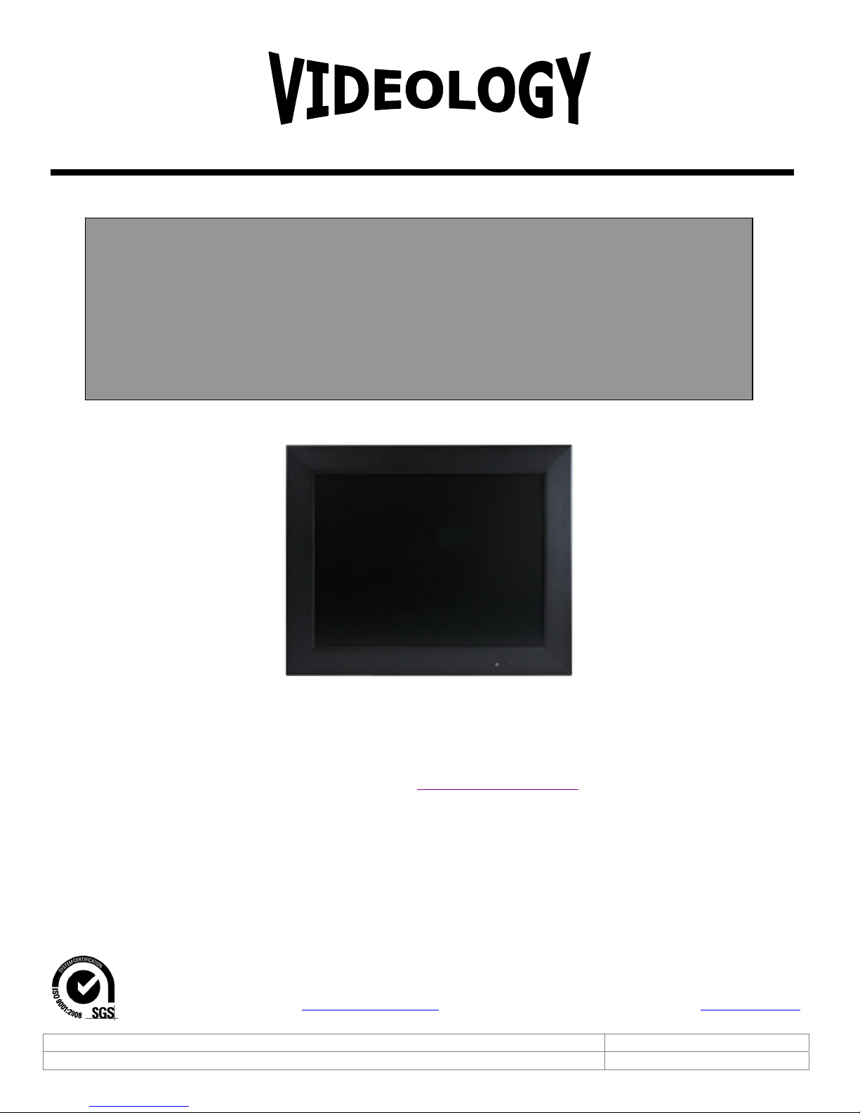
45M104 10.4” LCD
Original Equipment Manufacturer
Prior to Using This Document: Videology reserves the right to modify the information in this
document as necessary and without notice. It is the user’s responsibility to be certain they possess the
most recent version of this document by going to www.videologyinc.com, searching for the model
number, and comparing revision letters on the respective document, located in the document’s footer.
For technical assistance with this product, please contact the supplier from whom the product was
purchased.
Videology® Imaging Solutions, Inc. Videology® Imaging Solutions, Europe B.V.
Doc # INS-45M104 Issue Date: 5/15/2012
Revision: A Page 1 of 16
37M Lark Industrial Parkway
Greenville, Rhode Island 02828 USA
Tel: (401) 949 – 5332 Fax: (401) 949 – 5276
North/South American Sales: [email protected]
www.videologyinc.com
Neutronenlaan 4
NL-5405NH Uden, The Netherlands
Tel: +31 (0) 413 256261 Fax: +31 (0) 413 251712
European Sales: [email protected]
www.videology.nl
Page 2

License Agreement (Software):
This Agreement states the terms and conditions upon which Videology Imagin g Solut ion s, Inc. USA and
Videology Imaging S
olutions, B.V. Europe (hereafter referred to as "Videology
®
") offer to license to you the
software together with all related documentation and accompanying items including, but not limited to,
the executable programs, drivers, libraries, and data files associated with such software.
The Software is licensed, not sold, to you for use only under the terms of this Agreement.
Videology grants to you, the purchaser, the right to use all or a portion of this Software provided that the
Software is used only in conjunction with Videology's family of product s .
In using the Software you agree not to:
Decompile, disassemble, reverse engineer, or otherwise attempt to derive the source code for any
Product (except to the extent applicable laws specifically prohibit such restriction);
Remove or obscure any trademark or copyright notices.
Limited Warranty (Hardware and Software):
ANY USE OF THE SOFTWARE OR HARDWARE IS AT YOUR OWN RISK. THE SOFTWARE IS PROVIDED FOR
USE ONLY WITH VIDEOLOGY'S HARDWARE. THE SOFTWARE IS PROVIDED FOR USE "AS IS" WITHOUT
WARRANTY OF ANY KIND, TO THE MAXIMUM EXTENT PERMITTED BY LAW, VIDEOLOGY DISCLAIMS ALL
WARRANTIES OF ANY KIND, EITHER EXPRESS OR IMPLIED, INCLUDING, WITHOUT LIMITATION, IMPLIED
WARRANTIES OR CONDITIONS OF MERCHANTABILITY, QUALITY AND FITNESS FOR A PARTICULAR
APPLICATION OR PURPOSE. VIDEOLOGY IS NOT OBLIGATED TO PROVIDE ANY UPDATES OR UPGRADES
TO THE SOFTWARE OR ANY RELATED HARDWARE.
Limited Liability (Hardware and Software):
In no event shall Videology or its Licensor's be liable for any damages whatsoever (including, without
limitation, incidental, direct, indirect, special or consequential damages, damages for loss of business
profits, business interruption, loss of business information, or other pecuniary loss) arising out of the use
or inability to use this Software or related Hardw a re, including, but not limited to, any of Videology's
family of products.
Doc # INS-45M104 Issue Date: 5/15/2012
Revision: A Page 2 of 16
Page 3

Table of Contents
Document History ................................................................................................................. 4
1.
2. Warning ............................................................................................................................... 4
3. Precautions .......................................................................................................................... 4
Safety ..................................................................................................................................... 4
Installation .............................................................................................................................. 4
Cleaning .................................................................................................................................. 4
4. Federal Communications Commission (FCC) Statement ............................................................... 5
5. Features .............................................................................................................................. 5
6. Operating Instructions ........................................................................................................... 6
6.1. Key Board Control........................................................................................................... 6
6.2. Connectors .................................................................................................................... 7
6.3. Remote Control Operation ................................................................................................ 8
6.4. OSD Functions ............................................................................................................... 9
6.4.1. Source .................................................................................................................... 9
6.4.2. Item (Hot key, simple operation) ................................................................................ 9
6.4.3. OSD Menu .............................................................................................................. 9
7. PC Timing .......................................................................................................................... 13
8. LCD monitor Mounting Guide ................................................................................................ 13
9. Specifications ..................................................................................................................... 14
10. Appendixes ..................................................................................................................... 15
10.1. Troubleshooting ........................................................................................................ 15
11. Package List .................................................................................................................... 15
12. Contact Information ......................................................................................................... 16
Doc # INS-45M104 Issue Date: 5/15/2012
Revision: A Page 3 of 16
Page 4
1. Document History
Revision Issue Date Reason CN#
Rev A 02-22-2012 Initial release 12-0026
2. Warning
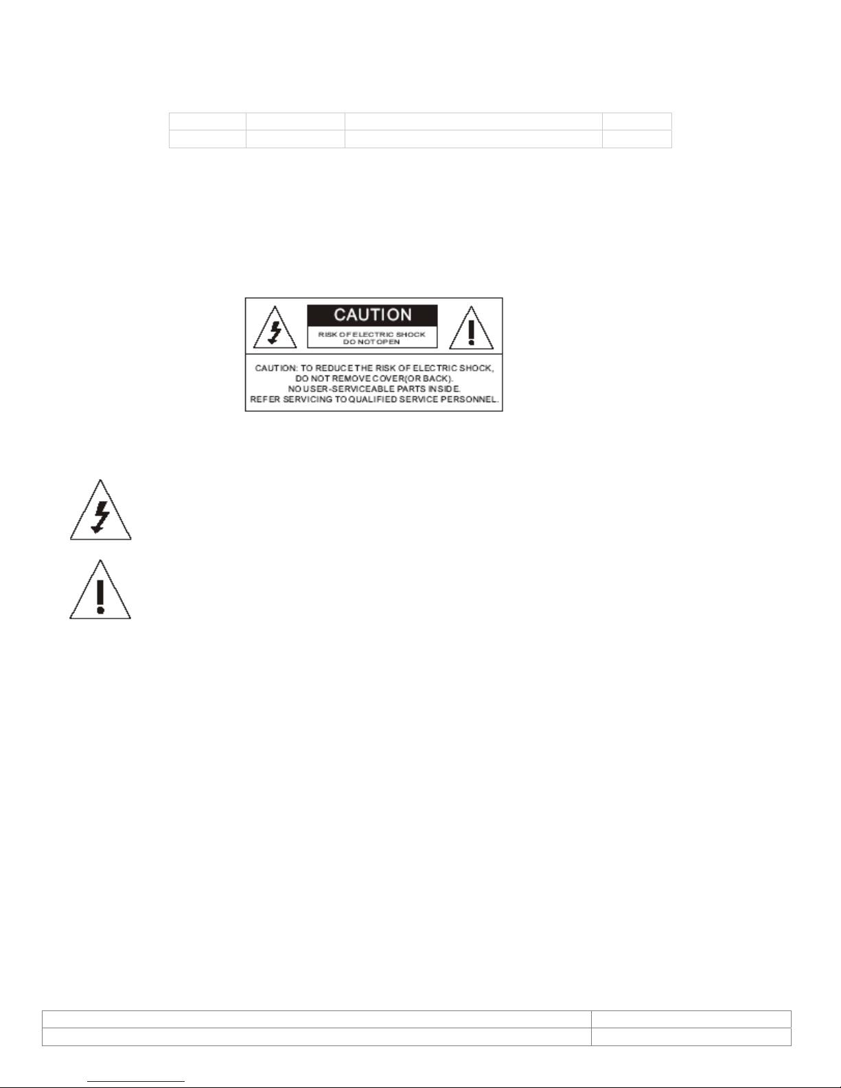
TO REDUCE THE RISK OF FIRE OR ELECTRIC SHOCK:
DO NOT EXPOSE THIS PRODUCT TO RAIN OR MOISTURE.
DO NOT INSERT ANY METALLIC OBJECT THROUGH VENTILATION GRILLS.
CAUTION:
Explanation of Graphical Symbols
The lightning flash with arrowhead symbol, within an equilateral triangle, is
intended to alert the user to the presence of non-insulated dangerous voltage
within the product's enclosure that may be of sufficient magnitude to
constitute a risk of electric shock to persons.
The exclamation point within an equilateral tr iangle is intended to alert the
user to the presence of important operating and maintenance (servicing)
instructions in the literature accompanyin g the product.
3. Precautions
Safety
Should any liquid or solid object fall into the cabinet, unplug th e unit and have it checked by the qualified
personnel before operating it any further. Unplug the unit from the wall outlet if it is not going to be used
for several days or more. To disconnect the cord, pull it out by the plug. Never pull the cord itself. Allow
adequate air circulation to prevent internal heat built-up. Do not place the unit on surfaces (rugs,
blankets, etc.) or near materials (curtains, draperies) that may block the ventilation holes.
Installation
Do not install the unit in an extremely hot or humid place or in a place subject to excessive dust or
mechanical vibration. The unit is not designed to be waterproof. Exposure to rain or water may damage
the unit.
Cleaning
Clean the unit with a slightly damp soft cloth. Use a mild household detergent. Never use strong solvents
such as thinner or benzine as they might damage the finish of the unit.
Retain the original carton and packing materials for safe transport of this unit in the future.
Doc # INS-45M104 Issue Date: 5/15/2012
Revision: A Page 4 of 16
Page 5
4. Federal Communications Commission (FCC) Statement
This Equipment has been tested and found to comply with the limits for a Class B digital device, pursuant
to Part 15 of the FCC rules. These limits are designed to provide reasonable protection against harmful
interference in a residential installation. This equipmen t generates, uses and can radiate radio frequency
energy and, if not installed and used in accordance with the in structions, may cause harmful interference
to radio communications. However, there is no guarantee that interference will not occur in a particular
installation. If this equipment does cause harmful interference to radio or television reception, which can
be determined by turning the equipment off and on, the user is encouraged to try to correct the
interference by one or more of the following measures:
Reorient or relocate the receiving antenna.
Increase the separation between the equipment and receiver.
Connect the equipment into an outlet on a circuit different from that to which the receiver is
connected.
Consult the dealer or an experienced radio/TV technician for help.
You are cautioned that changes or modifications not expressly approved by that party responsible for
compliance could void your authority to operate the equipment.
This device complies with Part 15 FCC Rules. Operation is subject to the
following two conditions:
(1) This device may not cause harmful interference.
(2) This device must accept any interference received including in terference
that may cause undesired performance.
5. Features
Special Video Processor
Inputs/Outputs: 1 BNC Composite Video, S-Video, 1CH Audio (RCA) & PC IN
PIP Control Function (Only PC/Video)
Screen protector (Anti-blur /Image auto move)
NTSC/PAL Auto Switch
3D De-interlace Technology
3D Comb Filter Technology
Automatic Color Control and Color Killer
Luminance transient improvement (LTI), Chrominance transient improvement (CTI)
Directional zoom engine
Auto termination (75 Ohms)
Built-in 2W+2W speaker
IR remote control enabled
VESA standard bracket 75/100mm
Wall mount capability
Doc # INS-45M104 Issue Date: 5/15/2012
Revision: A Page 5 of 16
Page 6
6. Operating Instructions
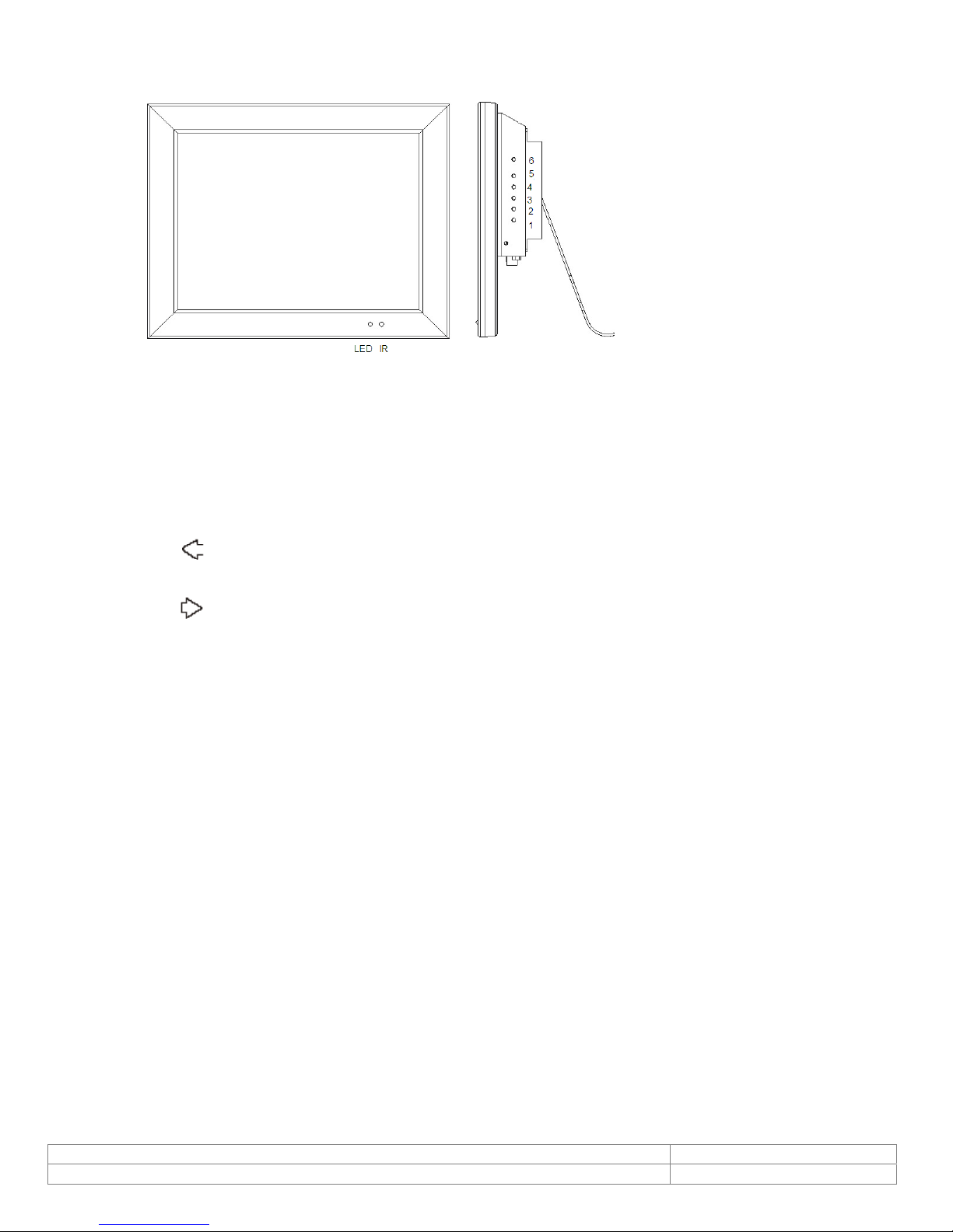
6.1. Key Board Control
1. Power
Monitor power ON / OFF. At OFF mode, monitor will be at standby status
Green Light -- Power On
Red Light -- Standby mode
2. Adjust
Increase the value on the OSD menu or turn ON / OFF function
3. Adjust
Decrease the value on the OSD menu or turn ON / OFF function
4. Item/Select
Choose sub menu Hot key selection for:
Brightness/ Contrast/ Backlight/ Sharpness/ Hue/ Color/ Volume
Press again to enter selected option
5. Menu/Function
OSD menu ON / OFF control
6. Source
SDE: Select input signal from AV1, S-Video or PC.
SHDE: Select input signal from AV1, AV2, S-Video, PC, HD.
Used as "Return/Exit" function in OSD menu
***Push “Menu” and “Up” into key-lock mode, and push again into unlock.***
Figure 1. Front and side Panel
Doc # INS-45M104 Issue Date: 5/15/2012
Revision: A Page 6 of 16
Page 7
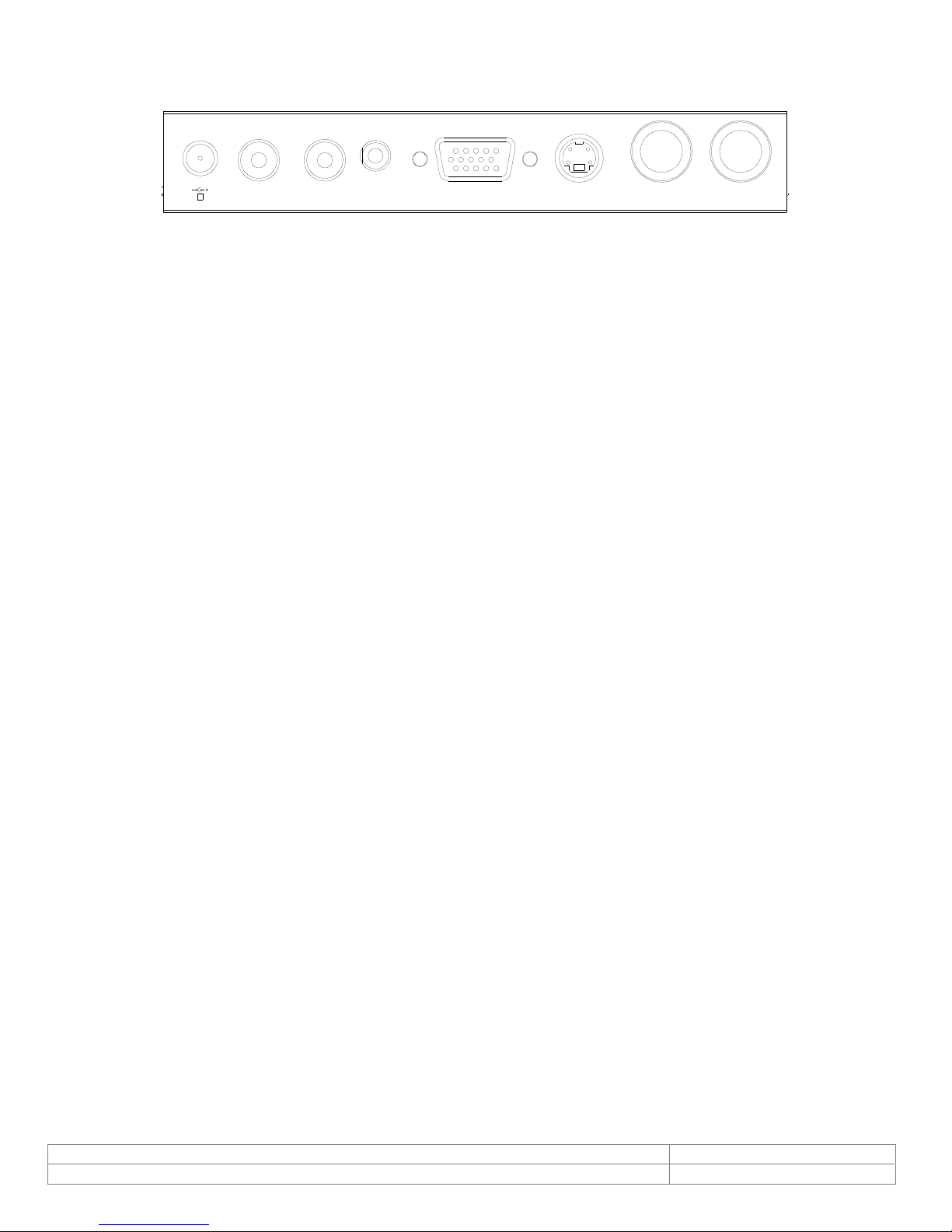
6.2. Connectors
5 6
DC12V
IN
1 2
1. Regulated DC12V Power Input
2. AUDIO R/L In
Audio Signal Input, this input is for Video and Y/C
3. PC AUDIO IN
4. PC IN
5. Y/C IN (S-Video)
6. Video IN/OUT
AUDIO
IN
3
PC AUDIO
IN
4
Figure 2. Back Panel
PC
IN
Y/C
IN
VIDEO
IN
VIDEO
OUT
Doc # INS-45M104 Issue Date: 5/15/2012
Revision: A Page 7 of 16
Page 8
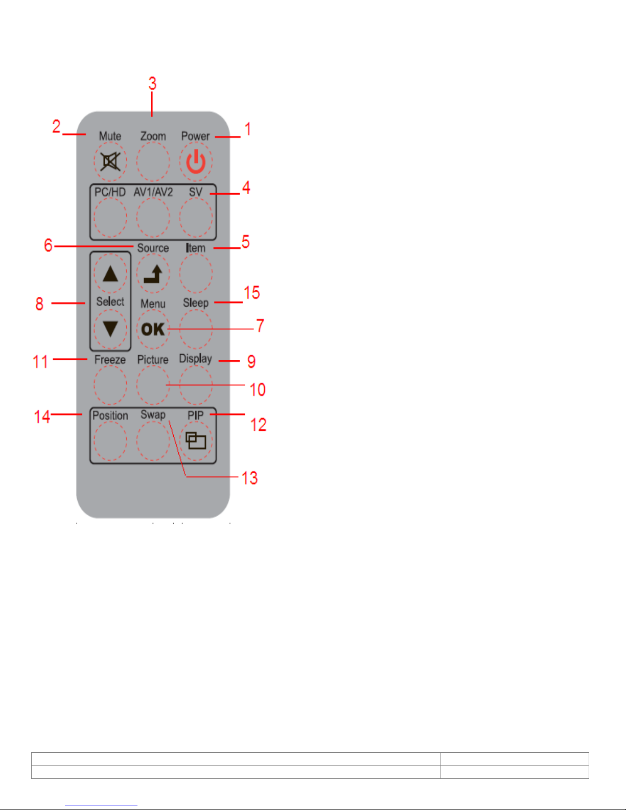
6.3. Remote Control Operation
1. Power: Push to turn on and turn off the unit.
2. Mute: Disable the unit's sound output, press the
button again or the Volume +/- button to restore the
volume.
3. Zoom: Toggle between the image ratios.
(4:3/16:9/14:9/Movie/Panorama)
4. PC/HD, AV1/AV2, SV: Press to choose the desired
signal source directly.
5. Item: As hot key selection for Brightness/Contrast/
Backlight/Sharpness/Hue/Color /Volume > adjust
6. Source/(Exit): Push to select input signal. Used as
"Return/Exit" function in OSD menu.
7. OK/Menu: Push to call out OSD menu.
"Confirm / OK" function in OSD menu.
Used
as
8. Select▲/▼: Change the function up or down.
9. Display: Press to display the information on the
screen, such as resolution, signal source.
10. Picture: Toggle between the different picture
modes. Standard /Soft/Personal /Bright.
11. Freeze: Press to freeze the picture (AV1, AV2,
SVideo), press again to restore.
12. PIP:
Press to activate the PIP function and select the
size of sub-picture Small/Medium/Large/1+1 / Off. Off
means PIP function is turned off.
13. Swap: In the PIP mode, press the butt on to switch the main picture and sub-picture. (This function
works only when sub-picture exists.)
14. Position: PIP mode Press to select the position of sub-picture.(4 corners and center)
15. Sleep: Select the Automatic turn off time.
Doc # INS-45M104 Issue Date: 5/15/2012
Revision: A Page 8 of 16
Page 9
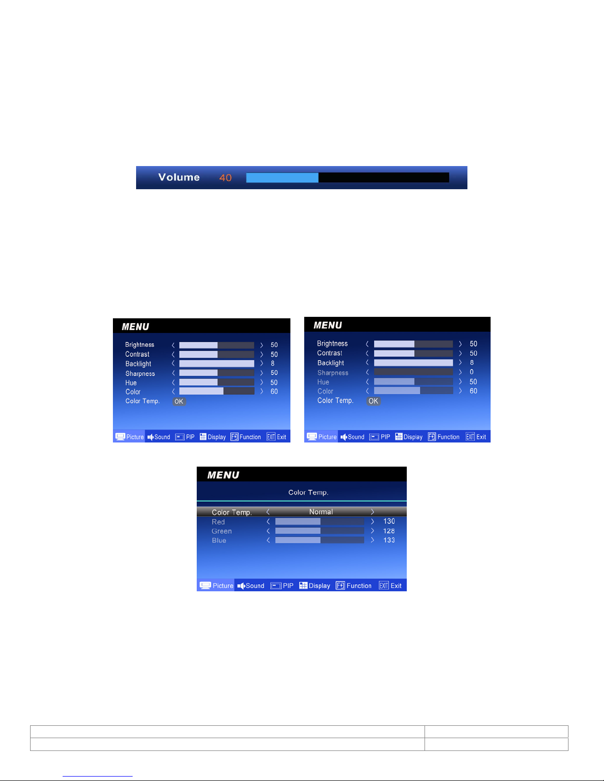
6.4. OSD Functions
6.4.1. Source
Push <Source>button to selection the channel (AV/SVIDEO/PC).
6.4.2. Item (Hot key, simple operation)
Use < Item > button as hot key to call out Adjust bar. Then use +/- button to increase/decrease the
menu bar. (Brightness/Contrast/Backlight/Sharpness/Hue/Color /Volume)
6.4.3. OSD Menu
Push <Menu>button to display the Main menu.
Main menu includes (Picture), (Sound), (PIP), (Display), (Function) and (Exit) 6 categories.
Use Select (▲▼) button to select the function category to be adjusted.
Push the Menu/
6.4.3.1. PICTURE
button to enter the selected category.
OK
(Mode: AV, S-VIDEO, HD) (Mode: PC D-Sub)
(Color Temp.)
Use Select (▲▼) button to select the item to be adjusted.
Push <Menu> to confirm the selected item;
Use Select (▲▼) button to adjust and then push <Source> button to return.
Doc # INS-45M104 Issue Date: 5/15/2012
Revision: A Page 9 of 16
Page 10
MENU FUNCTION MODE
Brightness
Contrast
Back light
Sharpness
Hue
Color
Use Select (▲▼) button to increase/decrease the screen brightness.
Use Select (▲▼) button to increase/decrease the screen contrast.
Use Select (▲▼) button to increase/decrease the screen backlight.
Use Select (▲▼) button to adjust the sharpness of the image.
Use Select (▲▼) button to adjust the hue of the image.
Use Select (▲▼) button to increase/decrease the image color
saturation.
Use Select (▲▼) button to select the desired color temperature.
Color Temp
There are Normal / Warmer / Warm / Cool / Cooler / User 6
modes. In User mode, push <MENU> button to enter and adjust the
Red/Green/Blue color separately.
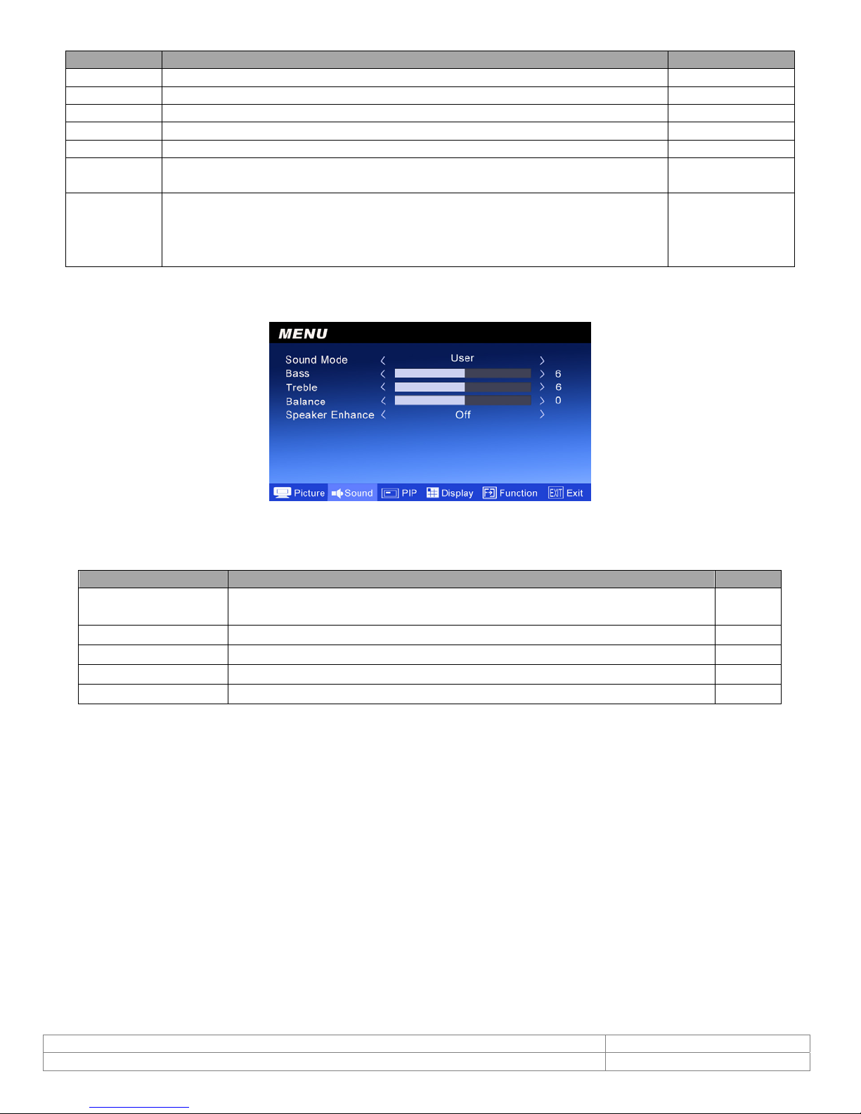
6.4.3.2. SOUND
all
all
all
AV/S-video/HD
AV/S-video/HD
AV/S-video/HD
all
Use Select (▲▼) button to select the item to be adjusted. Push
Select (▲▼)
button to adjust and then push <Source> button to return.
MENU FUNCTION MODE
Sound Mode
Bass
Treble
Balance
Speaker Enhance
Use
Select
Theater//Music/News/Original/User 5
Use
Select
Use
Select
Use
Select
Use
Select
(▲)(▼
(▲)(▼
(▲)(▼
(▲)(▼
(▲)(▼
button to select
)
button to adjust the Bass
)
button to adjust the Treble
)
button to adjust the left / right balance
)
button to select On/Off
)
Menu
to confirm the selected item, use
kinds of modes
all
all
all
all
all
Doc # INS-45M104 Issue Date: 5/15/2012
Revision: A Page 10 of 16
Page 11

6.4.3.3. PIP
Use Select (▲▼) button to select the item to be adjusted. Push
Select (▲▼)
MENU
PIP Source
PIP Size
PIP Swap
PIP Position
button to adjust and then push <Source> button to return.
FUNCTION
Use Select (▲▼) button to select the source of sub-picture.
Use Select (▲▼) button to select the size of sub-picture Small/Medium/Large/1+1/Off. Off
means PIP function is turned off.
Push <MENU> button to switch the main picture and sub-picture. (This function works only
when sub-picture exists )
Use Select (▲▼) button to select the position of sub-picture(0~5)
4 corners and center.(This function works only when sub-picture exists)
Menu
to confirm the selected item, use
6.4.3.4. Display
Use Select (▲▼) button to select the item to be adjusted. Push
Select (▲▼)
button to adjust and then push <Source> button to return.
to confirm the selected item , use
Menu
(Mode: AV, S-VIDEO, HD) (Mode: PC D-Sub)
MENU FUNCTION MODE
H. Position
V. Position
Image Ratio
Image
Optimize
Phase
Clock
Auto Adjust Push <MENU> button to adjust the best image. PC
Use Select (▲▼) button to adjust the horizontal position of the image.
Use Select (▲▼) button to adjust the vertical position of the image.
Use Select (▲▼) button to select the image ratio.
PC mode : 4:3/16:9
AV/S-VIDEO mode : 4:3/16:9/14:9/Movie/Panorama
Push <MENU> button to enter the sub-menu and use
adjust/select
Use Select (▲▼) button to increase/decrease the noise on the screen.
Use Select (▲▼) button to increase/decrease the snowflake noise on the screen.
Select (▲▼) button to
all
all
all
all
PC
PC
Doc # INS-45M104 Issue Date: 5/15/2012
Revision: A Page 11 of 16
Page 12
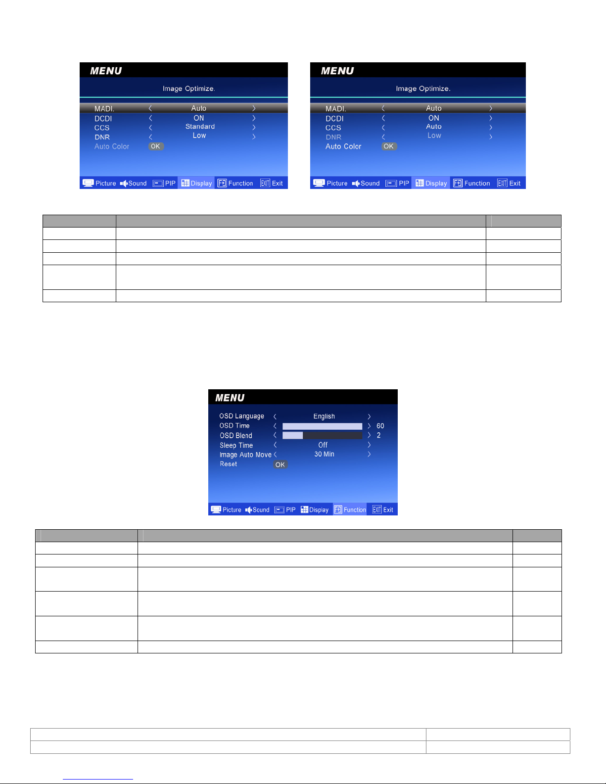
6.4.3.5. Image Optimize
f
(Mode: AV, S-VIDEO, HD) (Mode: PC D-Sub)
MENU FUNCTION MODE
MADI
DCDI
CCS
DNR
Auto Color Push <MENU> button to adjust the best image color. PC
Use Select (▲▼) button to select Auto/Off/Standard 3 kinds of modes.
Use Select (▲▼) button to select On/Off.
Use Select (▲▼) button to select
Use Select (▲▼) button to select Low/
Auto/Off/Standard 3 kinds of modes.
Medium/ High/ Of
4 kinds of modes.
all
all
all
AV/Svideo/HD
6.4.3.6. Function
Use Select (▲▼) button to select the item to be adjusted. Push
MENU
to confirm the selected item,
Use Select (▲▼) button to adjust and then push <Source> button to return.
MENU FUNCTION MODE
OSD Language
OSD Time
OSD Blend
Sleep Time
Image Auto Move
Use Select (▲▼)button to select the desired language.
Use Select (▲▼) button to increase/decrease the OSD display time.
Use Select (▲▼) button to increase/decrease the transparent degree of
the OSD display.
Use Select (▲▼) button to select the automatic turn off time.
Off/10/20/30/60/90/120/150/180 Min.
Use Select (▲▼) button to select
the image move time.
Off/30/60/90/120/180 Min.
Reset Push <MENU> button to return to factory default setting. all
all
all
all
all
all
Doc # INS-45M104 Issue Date: 5/15/2012
Revision: A Page 12 of 16
Page 13
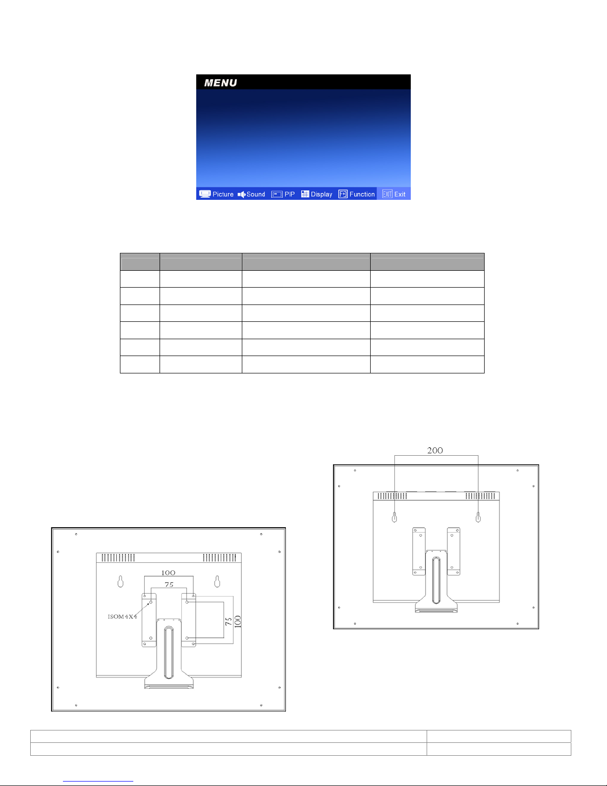
6.4.3.7. Exit
Push <MENU>to exit the OSD menu.
7. PC Timing
Mode Resolution Horizontal Frequency Vertical Frequency
1 800*600@60 37.879 60.317
2 800*600@72 48.077 72.188
3 800*600@75 46.875 75.000
4 1024*768@60 48.363 60.004
5 1024*768@70 56.476 70.069
6 1024*768@75 60.023 75.029
8. LCD monitor Mounting Guide
A. Desktop
Adjust the viewing angle of LCD to fit most comfortable monitoring status.
B. Wall mount
Free your space with wall mount design.
Please follow the fix-hole size in back panel to install
the LCD to the wall.
C. VESA Bracket
Doc # INS-45M104 Issue Date: 5/15/2012
Revision: A Page 13 of 16
Page 14
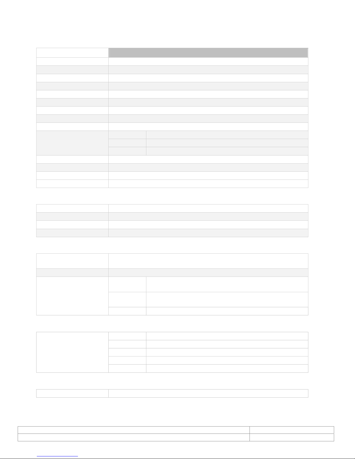
9. Specifications
Electrical 45M104
Operating System NTSC/ PAL/ XGA/ VGA/ SVGA
Picture Size 10.4” diagonal
Aspect Ratio 4:3
Resolution (H x V) 1024 x 768 pixels
Display Colors 16.2M
Brightness 300 (nit)
Contrast Ratio 500:1
Response Time 25ms
Backlight CCFL
Input Signal Video 1 CH 1Vp-p Composite video at 75 Ohms
S-video Y=1.0Vp-p w/neg. sync C=0.285Vp-p
PC Analog RGB
Video Angle Up 50°, Down 60°, Left 70°, Right 70°
Lamp Life-time 50,000 hrs
Power Source 12VDC/ 90~260V AC 60Hz/ 50Hz global switching power adapter
Power Consumption 3Amp
Environmental
Operating Temperature 0°C ~ 50°C (32°F ~ 122°F)
Operating Humidity 10% - 85% R.H.
Storage Temperature -10°C ~ 60°C (14°F ~ 140°F)
Storage Humidity 10% - 85% R.H.
Mechanical
Dimensions
W x H x D
Weight 2.2 kg (4.85 lbs)
Connectors Video 1 BNC inputs/output
Audio 1 RCA input/output
PC 1 15-pin D-sub connector
266.2mm x 213.3mm x 57.4mm
(10.48” x 8.4” x 2.26”)
1 S-video 4-pin Mini DIN
1 Ø3.5mm jack input
Accessories
Included Power supply
Power cord
15 pin D-sub
Remote control
Bracket: VESA 100/75 standard
Safety Standards
FCC, CE, UL
Doc # INS-45M104 Issue Date: 5/15/2012
Revision: A Page 14 of 16
Page 15
10. Appendixes
10.1. Troubleshooting
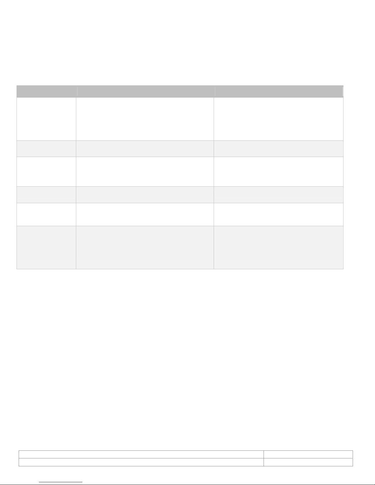
The tables provided below include some problems that the user may encounter while using the display and
the corresponding solutions. Please refer to the contents of this section prior to contacting service
personnel.
Problem Possible Causes Solutions
1. Make sure the power cable has been
1. Is the power cable connected to the unit?
No picture
Strange color
Picture distortion
Picture is too dim
Only sound
but no picture
Only picture
but no sound
2. Is the unit turned on?
3. Is the signal cable connected to the unit?
4. Is the unit in power saving mode?
1. Is the signal cable connected to the unit?
1. Is the signal cable connected to the unit?
2. Is the video input signal within the unit's
specified frequency range?
1. Have the unit's brightness and contrast
settings been set to the lowest level?
1. Is the connection of the input signal correct?
1. Is the signal cable connected to the unit?
2. Has the volume been set to the min level?
3. Is the audio cable connected to the unit?
Please contact the customer service center of your local dealer if you have any questions regarding the
unit after reading the information provided above.
properly connected to the unit.
2. Turn on the unit.
3. Make sure the signal cable has been
properly connected to the unit.
4. Press any key on computer keyboard.
1. Make sure the signal cable has been
properly connected to the unit.
1. Make sure the signal cable has been
properly connected to the unit.
2. Make sure the input signal is within the
unit's specified frequency range.
1. Adjust brightness and contrast
1. Check connection of input signal.
2. Make sure the signal cable has been
properly connected.
1. Make sure the signal cable has been
properly connected to the unit.
2. Adjust the volume to an appropriate
setting.
3. Make sure the audio cable has been
properly connected to the unit.
11. Package List
A. LCD Monitor x 1
B. Power Cord x 1
C. User Manual x 1
D. 12V Power Adapter x 1
E. Remote Control x 1
F. VGA Cable (DB-15) x 1
Doc # INS-45M104 Issue Date: 5/15/2012
Revision: A Page 15 of 16
Page 16

12. Contact Information
For technical assistance with this product, please contact the supplier from whom the product was
purchased.
For OEM inquiries, contact Videology Imaging Solutions:
North / South America:
Videology Imaging Solutions Inc.
37M Lark Industrial Parkway
Greenville, RI 02828
USA
Tel: (401) 949-5332
Fax: (401) 949-5276
Please visit our website at: http://www.videologyinc.com
VIDEOLOGY IMAGING SOLUTIONS is an ISO 9001 registered video camera developer and
manufacturer serving industrial, machine vision, biometric, security, and specialty OEM markets.
Videology designs, develops, manufactures, and distributes video, image acquisition, and display
technologies and products to OEMs worldwide.
Europe:
Videology Imaging Solutions Europe
Neutronenlaan 4
NL-5405 NH Uden,
Netherlands
Tel: +31 (0) 413 256 261
Fax: +31 (0) 413 251 712
Doc # INS-45M104 Issue Date: 5/15/2012
Revision: A Page 16 of 16
 Loading...