

Page 1
High Speed Pan/Tilt/Zoom Dome
This document provides technical information for the user. Videology reserves the right to
modify the information in this document as necessary. The customer should make sure that
they have the most recent manual version. Videology holds n o responsibility for any errors
that may appear in this document.
Instruction Manual
IMAGING SOLUTIONS INC.
20/21Z704T-PZ
Camera
Information may change without notice.
®
Videology Imaging Solutions, Inc. USA
37M Lark Industrial Parkway
Greenville, RI 02828
Tel: 401-949-5332
Fax: 401-949-5276
Doc # INS 20/21Z704T-PZ Issue Date: 03/22/2007
Revision: C Page 1 of 32
Videology Imaging Solutions, B.V. Europe
Neutronenlaan 4
NL-5405NH Uden, The Netherlands
Tel: +31 (0) 413-256261
Fax: +31 (0) 413-251712
Page 2

Table Of Contents
1. Important Safeguards........................................................................................ 4
2. Precautions ...................................................................................................... 5
2.1. Operating .................................................................................................. 5
2.2. Handling.................................................................................................... 5
2.3. Installation and Storage............................................................................... 5
3. Features .......................................................................................................... 6
3.1. Camera Specifications ................................................................................. 6
3.2. Pan/Tilt Functions ....................................................................................... 6
3.3. Preset, Pattern, Swing, Privacy Mask, Group Functions and More…..................... 6
3.4. PTZ Control................................................................................................ 6
3.5. OSD (On Screen Display) Menu..................................................................... 6
3.6. Alarm I/O Functions.................................................................................... 7
3.7. Easy Installation and Operation .................................................................... 7
3.8. Product & Accessories.................................................................................. 7
4. Installation....................................................................................................... 8
4.1. DIP Switch Setup........................................................................................ 8
4.1.1. Camera ID Setup ................................................................................. 8
4.1.2. Communication Protocol Setup............................................................... 9
4.2. Wall Mount Installation Using Wall Mount Bracket.......................................... 10
4.3. Ceiling Mount Installation Using Wall Ceilin g Bracket...................................... 12
4.4. Cabling.................................................................................................... 13
4.4.1. Power Connector................................................................................ 13
4.4.2. Video Cable....................................................................................... 13
4.4.3. RS-485 Communication....................................................................... 13
4.4.4. Alarm I/O.......................................................................................... 13
5. Operation....................................................................................................... 14
5.1. Check Points Before Operation.................................................................... 14
5.2. Starting OSD Menu ................................................................................... 14
5.3. Reserved Preset........................................................................................ 14
5.4. Relay Output Control................................................................................. 15
5.5. Preset ..................................................................................................... 15
5.6. Swing ..................................................................................................... 16
5.7. Pattern.................................................................................................... 16
5.8. Group ..................................................................................................... 17
5.9. Other Functions........................................................................................ 18
5.10. OSD Display of Main Screen.................................................................... 19
6. How To Use The OSD Menu............................................................................... 20
6.1. General Rules of Key Operation for Menu ..................................................... 20
6.2. Main Menu............................................................................................... 20
6.3. Display Setup........................................................................................... 20
6.4. Camera Setup.......................................................................................... 21
6.5. Motion Setup............................................................................................ 22
6.5.1. Park Action Setup............................................................................... 22
6.5.2. Origin Position Setup .......................................................................... 23
6.5.3. Alarm Input Setup.............................................................................. 23
6.5.4. Preset Setup...................................................................................... 24
6.5.5. Relay Output Setup ............................................................................ 24
6.5.6. Edit Preset Label ................................................................................ 25
6.5.7. Edit Preset Scene ............................................................................... 26
Doc # INS 20/21Z704T-PZ Issue Date: 03/22/2007
Revision: C Page 2 of 32
Page 3

6.6. Pattern Setup........................................................................................... 26
6.6.1. Record Pattern................................................................................... 26
6.7. Swing Setup ............................................................................................ 27
6.8. Group Setup ............................................................................................ 27
6.8.1. Action Setup...................................................................................... 28
6.9. Privacy Zone Mask Setup........................................................................... 28
6.9.1. Privacy Zone Position Setup................................................................. 29
7. Specifications.................................................................................................. 30
7.1. Ceiling Mount 78V0014.............................................................................. 31
7.2. Wall Mount 78V0013 ................................................................................. 31
8. Contact.......................................................................................................... 32
Doc # INS 20/21Z704T-PZ Issue Date: 03/22/2007
Revision: C Page 3 of 32
Page 4

1. Important Safeguards
Read Instructions
Read all of the safety and operating instructions before usin g the product.
Retain Instructions
Save these instructions for future reference.
Attachments / Accessories
Use only attachments or accessories recommended by the manufacturer. Using nonrecommended items may result in electrical hazards, damaged to the product and will void
the warranty.
Installation
Do not place or mount this product in or on an unstable or improperly supported location.
Improperly installed products may fall, causing serious injury to a child or adult, and
damage to the product. Use only with a mounting device recommended by the
manufacturer, or sold with the product. To insure proper mounting, follow the
manufacturer's instructions and use only mounting accessories recommended by the
manufacturer.
Power source
This product should be operated only from the type of power source indicated on the
marking label.
Doc # INS 20/21Z704T-PZ Issue Date: 03/22/2007
Revision: C Page 4 of 32
Page 5

2. Precautions
STOP!!! READ THIS BEFORE INSTALLATION
• Take packing material out o dome and cover off camera
• Use only 24VAC transformer (2A min)
• Use proper gauge wiring, (especially for power)
• Be sure to observe the RS-485 polarity
• Make sure of the camera setting:
o Check settings for Pelco-D, 9600 BAUD
(either will not change if energized, must reinitialize)
• SELECT “TR” (termination resister) to ON only if:
o For furthest dome away in multiple dome chain, or:
(Note: There can be multiple chains per channel when using a
distribution unit)
o For Single dome with cable greater than 500ft
Implement proper grounding for over power and lightning protection
2.1. Operating
Before using, make sure power supply and all cables are properly connected.
While operating, if any abnormal condition or malfunction is observed, stop using the
camera immediately and then contact your local dealer.
2.2. Handling
Do not disassemble or tamper with parts inside the camera.
Do not drop or subject the camera to shock and vibration as this can damage camera.
Care must be taken when you clean the clear dome cover. The dome can be easily
scratched.
2.3. Installation and Storage
Do not install the camera in areas of extreme temperature, which exceed the allowable
range.
Avoid installing in humid or dusty places.
Avoid installing in places where radiation is present.
Avoid installing in places where there are strong magnetic fields and electric signals.
Avoid installing in places where the camera would be subject to strong vibrations.
Doc # INS 20/21Z704T-PZ Issue Date: 03/22/2007
Revision: C Page 5 of 32
Page 6

3. Features
3.1. Camera Specifications
CCD Sensor: 1/4" Super HAD CCD
Zoom Magnification: 22x Optical Zoom, 10x Digital Zoom (Max. 220x Zoom)
Day & Night Function
DSS (Digital Slow Shutter) only works in day mode.
3.2. Pan/Tilt Functions
Max. 360°/sec high speed Pan/Tilt Motion
Using Vector Drive Technology, Pan/Tilt motions are accomplished with the shortest
path. As a result, time to target view is reduced dramatically and the video on the
monitor is very natural to watch.
For jog operation using a controller, since ultra slow speed 0.05°/sec can be reached, it
is very easy to aim the camera to the desired target view.
3.3. Preset, Pattern, Swing, Privacy Mask, Group Functions and More…
A maximum of 128 sets of position and zoom magnification are designated and stored as
Presets. For each Preset, additional information such as Dwell time (pause time in Group
action when camera reaches to a certain Preset position), Alarm action and area Label
can be assigned independently to meet to your requirements.
Max. 8 sets of Swing action can be stored. This enables the camera to move repetitively
between two preset positions with designated speed.
Max. 4 patterns can be recorded and played back. This enables the camera to follow any
trajectory controlled by joystick as closely as possible.
Max. 8 sets of Group action can be stored. This enables the camera to move repetitively
with combination of Preset or Pattern or Swing. A Group is composed of maximum of 20
entities of Preset/ Pattern/ Swings.
Max. 8 of Privacy masks can be located wherever it is required to protect private life.
3.4. PTZ Control
With RS-485 communication, a maximum of 99 of cameras can be controlled at the
same time.
Pelco-D or Pelco-P protocol can be selected as a control protocol in the current version of
firmware.
3.5. OSD (On Screen Display) Menu
An OSD menu is provided to display the status of camera and to configure the functions
interactively.
The information such as Camera ID, Pan/Tilt angle, Alarm I/O, Preset info can be
displayed on the screen if needed.
Doc # INS 20/21Z704T-PZ Issue Date: 03/22/2007
Revision: C Page 6 of 32
Page 7

3.6. Alarm I/O Functions
An optional Alarm I/O module is available for this camera. A maximum of 8 external
sensor inputs and 4 relay outputs can be utilized t o give more intelligence to your
applications.
If an external sensor is activated, camera can be set to move to the corresponding
preset position. Meanwhile, the output relay can be matched to some specific preset
positions to do counteractions such as turning on a light or sounding an alarm.
3.7. Easy Installation and Operation
This model is designed for outdoor environments. A Fan and Heater are built in the
housing and weather proof environmental structures are designed to meet international
standard IP66.
The camera housing and brackets are designed to be installed with a minimum of effort.
3.8. Product & Accessories
Included:
Options:
Camera Body Dome Cover Terminal blocks Screws
Wall mount bracket
(78V0013)
Ceiling Mount Bracket
(78V0014)
Alarm I/O Module
Doc # INS 20/21Z704T-PZ Issue Date: 03/22/2007
Revision: C Page 7 of 32
Page 8

4. Installation
4.1. DIP Switch Setup
Before you install the camera, please set the DIP switches on the PCB to configure the
camera ID, communication protocol and terminal resistor.
4.1.1. Camera ID Setup
×10 = 10’s digit and x1 = 1’s digit for decimal number. By
turning the arrow with a screwdriver, you can set up the
camera’s ID number.
For example, the left figure shows an example when Camera ID
is 1.
The range of ID is 1~99. Do not use 0 as camera ID. Factory
default of Camera ID is 1.
If you want to control a certain camera through the joystick
controller or DVR, you must match the camera ID with Cam ID
setting of the controller or DVR. Keep a list of the different
camera ID numbers and their locations.
Doc # INS 20/21Z704T-PZ Issue Date: 03/22/2007
Revision: C Page 8 of 32
Page 9
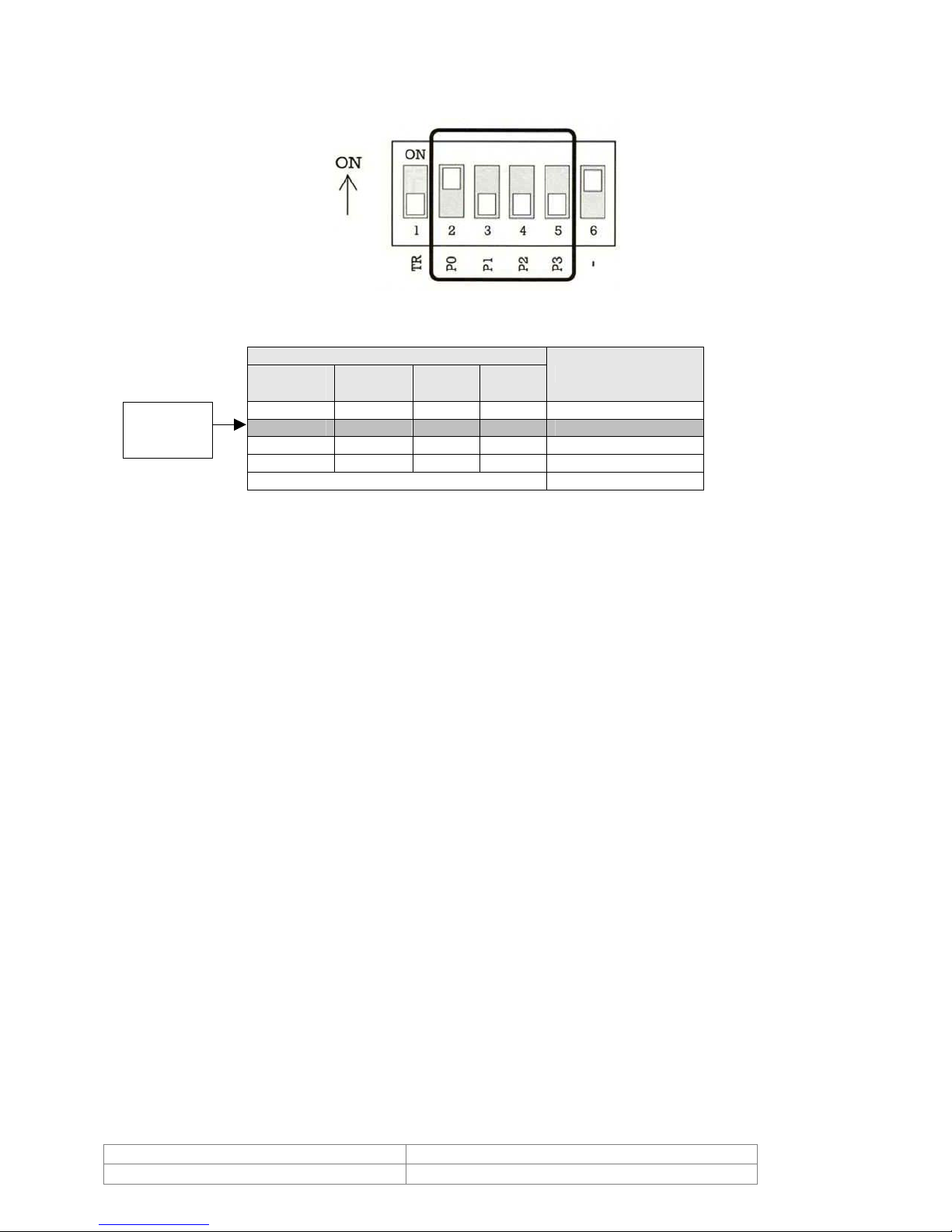
4.1.2. Communication Protocol Setup
Select the appropriate Protocol with a DIP switch combination.
Default
Setting
P0
(Pin 1)
OFF OFF OFF OFF PELCO-D, 2400 bps
ON OFF OFF OFF PELCO-D, 9600 bps
OFF ON OFF OFF PELCO-P, 4800 bps
ON ON OFF OFF PELCO-P, 9600 bps
Otherwise Reserved
If you want to control using a DVR or P/T controller, their protocol must be identical to
camera. Otherwise, you will not be able to control the camera.
Any changes made to the camera protocol by changing the DIP S/W will be effective after
you reboot the camera.
Factory default of protocol is ‘Pelco-D, 9600 bps’.
Switch State
P1
(Pin 2)
(Pin 3)
P2
P3
(Pin 4)
Protocol/Baud rate
Doc # INS 20/21Z704T-PZ Issue Date: 03/22/2007
Revision: C Page 9 of 32
Page 10
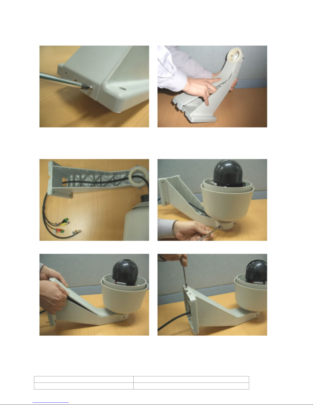
4.2. Wall Mount Installation Using Wall Mount Bracket
1 Unscrew the screw of the back cover of
the wall mount.
3 Pass the cable through the holes inside
the bracket as shown in picture bellow.
2 Take out the back cover from the body.
4 Attach the camera body to the wall
mount bracket. Test security of screws
and camera body before turning camera
into hanging position.
5 Assemble the cover on to the bracket. 6 Tighten the screws to fix the cover.
Doc # INS 20/21Z704T-PZ Issue Date: 03/22/2007
Revision: C Page 10 of 32
Page 11

7 Secure the bracket on the wall using the
included screws.
8 Remove the transparent lens shield
cover.
9 Attach the dome cover using the included
screws.
10 This is the final appearance after
installation.
Doc # INS 20/21Z704T-PZ Issue Date: 03/22/2007
Revision: C Page 11 of 32
Page 12

4.3. Ceiling Mount Installation Using Wall Ceiling Bracket
1 Install the Ceiling mount Bracket to the
Ceiling.
2 Pass the cables through the hole of the
bracket.
3 Test the security of screws before
4 Take off the clear lens protection cover.
attaching the camera. Attach the camera
to the Bracket using the included screws.
5 Turn the gray ring to place screw hole at
the right position.
Doc # INS 20/21Z704T-PZ Issue Date: 03/22/2007
Revision: C Page 12 of 32
6 Attach the gray ring with the clear cover
using the included screws.
Page 13

4.4. Cabling
4.4.1. Power Connector
Please, check the voltage and current capacity of power carefully. The rated electrical power
to operate this camera is AC 24V / 2A. The current must be 2A or higher.
After you assemble the power adaptor wires to the included 3 pin terminal block, plug it into
the power connector. Note that the center pin has no connection.
4.4.2. Video Cable
Connect with BNC coaxial cable.
4.4.3. RS-485 Communication
After assembling communication wires to the included 2 pin terminal
block, plug it into the communication connector. The D+, D- line
should be connected ‘+’, and ‘-’ pins respectively.
4.4.4. Alarm I/O
Use this connecter if you have an Alarm I/O module. If you need more detailed information,
please refer to the user’s manual of the alarm I/O module.
Doc # INS 20/21Z704T-PZ Issue Date: 03/22/2007
Revision: C Page 13 of 32
Page 14

5. Operation
5.1. Check Points Before Operation
Before power is applied, please, check the cables carefully.
The camera ID of the controller must be identical to that of the target camera. The camera
ID can be checked by reading the DIP switch of the camera.
If your controller supports multi-protocols, the protocol must be changed to match that of
the camera.
If you changed the camera protocol by changing DIP S/W, the change will be effective after
you reboot the camera.
Since the operation method can be different for each available controller, refer to the
manual for your controller. If the camera cannot be controlled properly, the operation of this
manual is based on the standard Pelco
Since Preset 95 is reserved to start the OSD menu, this cannot be used as regular Presets.
Therefore, the description “Preset 1~128” always means excluding Preset 95 in this manual.
®
Controller.
5.2. Starting OSD Menu
Function
Using the OSD menu, Preset, Pattern, Swing, Group and Alarm I/O function can be
configured for each application.
Start Menu
After type the numeric key 95, press the Preset key to start OSD menu.
[95] + [Preset]
5.3. Reserved Preset
Description
Some Preset numbers are reserved to special functions.
Function
Preset 95 : Menu Select
Preset 131~134 : Pattern Move
Preset 141~148 : Swing Move
Preset 151~158 : Group Move
Preset 161~164 : Relay Output Control
Doc # INS 20/21Z704T-PZ Issue Date: 03/22/2007
Revision: C Page 14 of 32
Page 15

5.4. Relay Output Control
Function
From the joystick controlled keyboard or DVR, the relay output can be controlled by the
Preset function. The output can be changed according to preset settings if you send the
preset command.
To set “ON”.
After typing (Relay Number + 160), press Preset key longer than 2 seconds.
[161~164] + [Preset] (longer than 2 sec.)
Ex)
To set “ON” Relay 4: [164] + [Preset] (longer than 2 sec)
To set “OFF”
After typing (Relay Number + 160), press Preset key.
[161~164] + [Preset]
Ex)
To set “OFF” Relay 4: [164] + [Preset]
To set “ON” Relay 1: [161] + [Preset] (longer than 2 sec)
To set “OFF” Relay 1: [161] + [Preset]
5.5. Preset
Function
A maximum of 127 positions can be stored as a preset position. The Preset number can be
assigned from 1 to 128 but 95 is reserved for displaying the OSD menu. Using the preset
key together with numeric keys in the controller, presets can be stored or executed quickly.
If you want to change the factory default of the preset configuration (i.e. Label 1 of preset is
blank, dwell time is 3 sec and relay out is OFF.), those settings for each preset can be
configured using the OSD menu.
Set Preset
After you type 1 ~ 128 numeric key, press Preset key for longer than 2 seconds.
[1 ~ 128] + [Preset] (press longer than 2 seconds)
Run Preset
After you type 1 ~ 128 numeric key, press Preset key quickly.
[1 ~ 128] + [Preset] (press shortly)
Delete Preset
To delete presets, use the OSD menu.
Doc # INS 20/21Z704T-PZ Issue Date: 03/22/2007
Revision: C Page 15 of 32
Page 16

5.6. Swing
Function
By using the swing function, we can make the camera move between 2 preset positions
repeatedly. The swing speed can be selected from 3 steps i.e. FAST, NORMAL and SLOW.
The speed for FAST, NORMAL and SLOW mode is 60°/sec, 30°/sec and 15°/sec respectively.
Set Swing
To set the swing, use the OSD menu.
Run Swing
< Using controller with Pattern key >
After you type a numeric key Swing No. + 10 (i.e. 11~18), press Pattern
key in the controller.
[11~18] + [Pattern]
Ex) If Swing number is 3, press 13 + Pattern
< Using controller without Pattern key >
After type 140+Swing No. (i.e. 141~148), press Preset key in the
controller.
[141~148] + [Preset]
Ex) If Swing number is 3, press 143 + Preset
Delete Swing
To delete the swing, use the OSD menu.
5.7. Pattern
Function
Pattern enables us to save and play back the camera motions created when moving the
joystick. A maximum of 4 Patterns can be used and can have a maximum recording of 1
minute per pattern.
Set Pattern
Patterns can be created by one of the following two methods.
Using the key of the controller: [1~4]+ Pattern (press longer than 2 seconds)
After you type 1 ~ 4 numeric key, press Pattern key for longer than 2
seconds to start Pattern recording.
Move the camera using the Joystick to make your pattern.
Maximum recording time is 1 min. The time remained will be displayed by
% on the screen.
To save the recording, press Near key and to cancel the recording, press
Far key.
Doc # INS 20/21Z704T-PZ Issue Date: 03/22/2007
Revision: C Page 16 of 32
Page 17

Using the OSD Menu: See the section “How to use the OSD Menu”.
Run Pattern
< Using the controller with the Pattern key >
After you type a numeric key Pattern No. (i.e. 1~4), press Pattern key in
the controller.
[1~4] + [Pattern]
Ex) If Pattern number is 3, press 3 + Pattern
< Using the controller without the Pattern key >
After type 130+Swing No. (i.e. 131~138), press Preset key in the
controller.
[131~134] + [Preset]
Ex) If the pattern number is 3, press 133 + Preset
Delete Pattern
Use the OSD menu to delete a Pattern.
5.8. Group
Function
The group function allows running a sequence of Presets, Patterns and/or Swings. Max 8
groups can be stored. Each group can have a max 20 action entities, which can be preset,
pattern or swing. The group can be created, modified and deleted using the menu. Also, the
dwell time defined in the preset menu is effective when a group is running.
Set Group
Use the OSD Menu to create a Group.
Run the Group
< Using the controller with the Pattern key >
After you type a numeric key 20+Group No. (i.e. 21~28), press Pattern key
in the controller.
[21~28] + [Pattern] Ex) If group number is 5, press 25 + Pattern
< Using the controller without the Pattern key >
After type 150+Group No. (i.e. 151~158), press Preset key in the
controller.
[151~158] + [Preset] Ex) If Swing number is 5, press 155 + Preset
Delete Group
Use the OSD Menu to delete.
Doc # INS 20/21Z704T-PZ Issue Date: 03/22/2007
Revision: C Page 17 of 32
Page 18

5.9. Other Functions
Power Up Action
This function enables the camera to resume the last action executed before power down.
Most actions such as Preset, Pattern, Swing and Group are available for this function but Jog
actions are not available to resume.
Auto Flip
If the tilt angle exceeds - 90°, Pan is automatically turned to the opposite direction (+180°)
to track the target continuously.
Park Action
This function enables the camera to locate a specific position automatically if the operator
doesn’t operate the controller for a while. The Park Time can be defined as an interval from
1 min. to 4 hours.
Origin Position
Using this function, the origin position can be defined by the operator. The Pan angle display
will be changed if you change the origin position. It is not ed that the tilt angle is not
affected by this function.
Alarm I/O
If you use the optional Alarm I/O module, you can take advantage of 8 alarm inputs and 4
alarm outputs. If an external sensor is activated, the camera can be set to move to a
corresponding preset position. Also, the output relay can be matched to some specific
preset positions to do counteractions, such as turning on a light or sounding an alarm. It is
noted that the last alarm input is effective if mult iple sensors are activated.
Privacy Mask
To protect privacy, a maximum of 8 white masks can be created on the arbitrary position to
hide objects such as windows, shops or private houses. It is noted that some mismatches or
misalignment can be realized since the OSD display is slow and its minimum resolu tion is
limited to a character size.
Doc # INS 20/21Z704T-PZ Issue Date: 03/22/2007
Revision: C Page 18 of 32
Page 19

5.10. OSD Display of Main Screen
P/T/Z Information
Current Pan/Tilt angle in degree and zoom magnificat ion.
Camera ID
Current Camera ID.
Action Title
The following is the possible Action Titles and their meaning.
"SPRESET ×××" When Preset xxx is stored
"PRESET ×××" When camera reach to Preset ×××
"UNDEFINED" When undefined Preset number is called to move
"SWING ×- ×××" When Swing × is in action
Preset Label
The label is stored for a specific Preset.
Alarm Information
This information shows current state of Alarm I/O. The character ‘O’ of first line stands for
Output and ‘I’ of second line means Input. If an I/O point is ON state it will show a number
corresponding to each point. If an I/O point is OFF state, '-' will be displayed.
Ex) Point 1, 7 of inputs are ON and 2, 4 of outputs are ON state. The OSD will
show as bellow
Doc # INS 20/21Z704T-PZ Issue Date: 03/22/2007
Revision: C Page 19 of 32
Page 20

6. How To Use The OSD Menu
6.1. General Rules of Key Operation for Menu
The menu items surrounded with ( ) always have a sub menu.
For all menu levels, go into the sub menu, press the Near key, to go to the upper menu,
press the Far key. The operation is easier to understand if you see the Near key as an enter
key, and the Far key as the Esc key.
To move from item to item in the menu, use the joystick Up/Down or Left/Right.
If you want to confirm a menu item, press Near.
To change a value of an item, use Up/Down of the joystick on the controller.
After you change a value, press Near key to save it or press Far key to cancel it.
6.2. Main Menu
System Information
Display System Information.
Display Setup
Enable/Disable of OSD display on Main Screen.
Dome Setting
Configure Various Functions of this camera.
Factory Reset
Return to Factory default configuration.
6.3. Display Setup
This menu defines Enable/Disable of the OSD display on
Main Screen. If an item is set to AUTO, the item is
displayed only when the value of it is changed.
Camera ID [ON/OFF]
Action Title [ON/OFF/AUTO]
PTZ Information [ON/OFF/AUTO]
Preset Label [ON/OFF/AUTO]
Alarm Information [ON/OFF/AUTO]
All Privacy [ON/OFF]
Doc # INS 20/21Z704T-PZ Issue Date: 03/22/2007
Revision: C Page 20 of 32
Page 21

6.4. Camera Setup
Setup the general functions of zoom camera module.
Digital Zoom [ON/OFF]
Focus Mode [AUTO/MANUAL]
Back Light [ON/OFF]
Day/Night [AUTO/DAY/NIGHT]
White Balance [AUTO/SPECIAL/INDOOR/
OUTDOOR/ MANUAL/ PUSH AUTO]
Flickerless
If the camera is used with 50Hz fluorescent lighting, there is a flicker on the screen. In this
case, it should be set to "ON". However the flickerless function should be set to "OFF" in
60Hz power source situations. The flickerless mode helps overcome flickering on the screen
in cases where the AC power frequency is different from the vertical sync frequency of the
camera.
When the flickerless function is set to "ON", DSS (Digital Slow Shutter) function does not
(*
work.)
(DSS operates only in “DAY” mode.)
Line Lock Sync [ON/OFF]
If Line lock sync is ON, the video signal is synchronized with AC power.
Reset Camera
Initialize the zoom camera module.
* [ON/OFF]
Doc # INS 20/21Z704T-PZ Issue Date: 03/22/2007
Revision: C Page 21 of 32
Page 22

6.5. Motion Setup
Setup the general functions of Pan/Tilt motions.
Power Up Action [ON/OFF]
Auto Flip [ON/OFF]
Jog Speed [FAST/NORMAL/SLOW]
The nominal jog speed is listed below when zoom is x1.
As zoom magnification is increased, the speed will be
decreased to maintain equal controllability.
FAST 160 °/sec
NORMAL 80 °/sec
SLOW 40 °/sec
Jog Direction [INVERSE/NORMAL]
If you set this to ‘Inverse’, the view in the screen moves in the same direction with jog
tilting. If ‘Normal’ is selected, the view in the screen moves in the reverse direction.
Park Action
Activate Park function.
Origin Position
Redefine particular pan position to Origin.
Alarm Define
Match the Alarm senor input to one of current Preset positions.
6.5.1. Park Action Setup
This function enables the camera to locate a specific position automatically if operator
doesn’t operate the controller for a while. The Park Time can be defined as an interval from
1 minute to 4 hours.
Park Enable [ON/OFF]
Park Time [1 min ~ 4 hours]
The time is displayed with "hh:mm:ss" format and you
can change this by 1 min unit.
Park Action [Preset 1~128]
Doc # INS 20/21Z704T-PZ Issue Date: 03/22/2007
Revision: C Page 22 of 32
Page 23

6.5.2. Origin Position Setup
6.5.3. Alarm Input Setup
You can redefine a particular pan position to the origin
position.
Origin Position [ON/OFF]
Set Origin Position
If you choose this menu, you can move the pan position
by using the joystick and redefine the origin.
Match the Alarm sensor input to one of the preset
positions. If an external sensor is activated, the camera
will move to the corresponding preset position when this
item is predefined.
Alarm × Action [NOT USED, PRESET 1~128]
Assign counteraction to the preset position for each Alarm
input.
Doc # INS 20/21Z704T-PZ Issue Date: 03/22/2007
Revision: C Page 23 of 32
Page 24

6.5.4. Preset Setup
Preset Number [1~128]
Select a preset number to create or modify. If the current
Preset number is predefined, the camera will move to the
stored position and zoom automatically to check them.
Otherwise, “UNDEFINED” will be displayed.
Dwell Time [1 sec ~ 4 min]
The time is displayed with "hh:mm:ss" format.
Edit Relay Out
Define Relay output. If an Output point is in the ON state, it will show a number
corresponding to each point. Otherwise '-' will be displayed.
Edit Preset Label
Edit the Label for a specific Preset position. A Label can be named with max 13 ch aract ers.
This label is automatically displayed on the upper left corner of the screen whenever you
move to the corresponding preset position.
Edit Preset Scene
Redefine the current Preset scene position (i.e. PTZ).
Clear Preset
Delete current Preset data
6.5.5. Relay Output Setup
Doc # INS 20/21Z704T-PZ Issue Date: 03/22/2007
Revision: C Page 24 of 32
Relay Out × [ON/OFF]
Toggle the corresponding relay output state to [ON/OFF].
Page 25

6.5.6. Edit Preset Label
The blinking cursor of LABEL represents the current
position to be selected from the set of characters bellow.
If you choose a character, the cursor will move to the
right.
Using Left/Right/Up/Down of the joystick, move to an appropriate character from the
Character set. To choose that character, press the Near key.
If you want to select a blank, choose Space character (" "). If you want to delete a
character before, use the back space character (" ←").
If you complete the Label editing, move cursor to "OK" and press Near key to save
completed label. To abort current changes, move cursor to "Cancel" and press Near key.
Doc # INS 20/21Z704T-PZ Issue Date: 03/22/2007
Revision: C Page 25 of 32
Page 26

6.5.7. Edit Preset Scene
6.6. Pattern Setup
Using the Joystick, move the camera to the desired
position.
By pressing the Near key, save the current PTZ data.
Press the Far key to cancel.
Pattern Number [1~4]
Select the pattern number to edit.
If the pattern selected does not exist, “UNDEFINED”
will be displayed as shown bellow.
Program Pattern
If you choose this, you will go to the sub menu to record a pattern .
Clear Pattern [ON/OFF]
6.6.1. Record Pattern
By using the Joystick, move to the start position with the
appropriate zoom. To start the pattern recording, press
the Near key. To exit this menu, press the Far key.
Maximum recording time is 1 min. The time remained will
be displayed by % on the screen.
While you are moving and zooming the camera, the
trajectory is controlled by the joystick and will be
recorded at the same time.
If you press the N ear key, the data w ill be sav ed and this
menu is exited. If you press the Far key, the date
recorded up to now will be abandoned and this menu is
exited.
Doc # INS 20/21Z704T-PZ Issue Date: 03/22/2007
Revision: C Page 26 of 32
Page 27

6.7. Swing Setup
Swing Number [1~8]
Select Swing number to create or modify. If the current
Swing number is not defined, as shown bellow,
"UNDEFINED SWING" is displayed above the 1st
Position and 2nd Position.
1st Position [PRESET 1~128]
2nd Position Define 2 Preset positions for Swing motion. If you assign
undefined Preset to one of these positions, "UNDEFINED
PRESET" will be displayed as shown bellow.
Swing Speed [FAST/NORMAL/SLOW]
Set the Swing speed level. The swing speeds is as shown bellow.
FAST 60 °/sec
NORMAL 30 °/sec
SLOW 15 °/sec
Loop [1~3]
This number represents how many swing motion will be repeated when swing is executed
within a Group. However, Swing motion will be repeated indefinitely if you execute the
Swing function.
Clear Swing
Delete current Swing data.
6.8. Group Setup
Group Number [1~8]
Action [x000, P1~P128, S1~S8, T1~T4]
x000 means no action is selected. If you assign Preset, it
will shows P1~P128. If you assign Swing, S1~S8 will be
displayed. If you assign Pattern, T1~T4 will be displayed.
If no action is defined, it will be skipped when Group
function is executed.
Clear Group
Delete all of 20 Action entities. All entities will become
x000 if you execute this.
Doc # INS 20/21Z704T-PZ Issue Date: 03/22/2007
Revision: C Page 27 of 32
Page 28

6.8.1. Action Setup
1. Using the Up/Down key select a
Group Number to modify. Then
press the Near key.
2. Using the Joystick, move to an
entity to be modified. Then press
the Near key.
3. Using the Up/Down key, select the
appropriate Action (x, P, S or T).
Then press the Near key. If you
press the Far key, the value
changed will be ignored and the
cursor will jump to the upper level
(i.e. 2).
4. Using the Up/Down key, select a
number you want. Then press the
Near key. If you press the Far
key, the number will be ignored
and cursor will jump to the upper
level (i.e. 2).
5. If the modification is completed,
move to the "OK" position on the
right of the map and press the
Near key to finish.
6.9. Privacy Zone Mask Setup
Doc # INS 20/21Z704T-PZ Issue Date: 03/22/2007
Revision: C Page 28 of 32
Privacy Number [1~8]
Display On/Off [ON/OFF]
Enable or disable the display of Privacy Zone Masking.
Set Privacy Mask
Go down to the sub menu to program the Privacy Zone.
Clear Privacy Mask
Delete current Privacy Zone Mask data.
Page 29

6.9.1. Privacy Zone Position Setup
1. By using the joystick, move to the scene to
hide with mask. Adjust the zoom ratio
properly since the mask will be created as
full screen size. If you finished the
masking, press the Near key to show the
mask on the screen or press the Far key to
cancel.
2. After the privacy mask is displayed, press
the Near key to save or press the Far key
to abandon.
3. After you exit the Privacy Mask menu, you
will see the mask whenever you move to
the location privacy zone is assigned. The
number in the center of the mask
represents the Privacy mask number. A
maximum of 8 zones can be located
wherever needed to protect privacy. It is
noted that some mismatch or misalignment
can be realized since the OSD display is
slow and its minimum resolution is limited
to a character size.
Doc # INS 20/21Z704T-PZ Issue Date: 03/22/2007
Revision: C Page 29 of 32
Page 30

7. Specifications
Electrical
20Z704T-PZ
NTSC
21Z704T-PZ
PAL
CCD sensor 1/4'' Super HAD CCD
Max. Pixels 811 (H)´508 (V) 410K 795 (H)´596 (V) 470K
Effective Pixels 768 (H)´494 (V) 380K 752 (H)´582 (V) 440K
Horizontal resolution 480 TVL
Sensitivity 1.0 Lux (Day) / 0.001 Lux (Night, DSS)
Day / night Auto / Day / Night
Focus Auto / Manual
Signal to noise ratio > 48 dB (AGC Off)
Back light compensation On / Off
White balance Auto / Manual / Indoor / Outdoor
Iris Auto
Power supply 24VAC (12VDC optional)
Power consumption 2A
Control communication RS-485 (Max. 99 unit.)
Protocol Pelco-D, Pelco-P Selectable
Environment
Operation temperature -30°C ~ 50°C
Mechanical
Dimensions Dome: 152mm Ø (6”)
Housing: 214mm Ø x H 260mm (8.4” Ø X H 10.2”)
Weight Approx 2.5 Kg
Focus range f=3.9~85.8mm
Zoom 22x optical / 10x digital
Auto focus speed 1 ~ 4.5 sec (depends on light condition)
O.S.D. control Menu / PTZ info
Pan / tilt range Pan 360° (endless) / tilt 90°
Pan / tilt speed
Preset: 360°/sec
Manual: 0.05°~160°/sec (proportional to zoom)
Swing:15~60°/sec
Pan / tilt preset 127 preset functions (with editable labels)
Pan / tilt pattern 4 joystick patterns (1min record time)
Pan / tilt swing 8 swing speeds
Pan / tilt group 8 group functions running
(presets, patterns, and/or swings)
Privacy zone mask 8 white privacy protection masks
Alarm I/O (optional) 8 input / 4 output
Fan / heater Built in
Accessories
LCD display joystick 60ZRC200
Wall mount (optional) 78V0013
Ceiling mount (optional) 78V0014
* Specifications of this product can be subjected to change without notice.
Doc # INS 20/21Z704T-PZ Issue Date: 03/22/2007
Revision: C Page 30 of 32
Page 31

7.1. Ceiling Mount 78V0014
7.2. Wall Mount 78V0013
Doc # INS 20/21Z704T-PZ Issue Date: 03/22/2007
Revision: C Page 31 of 32
Page 32

8. Contact
To contact Videology Imaging Solutions:
North / South America:
Videology Imaging Solutions Inc.
37M Lark Industrial Parkway
Greenville, RI 02828
USA
Tel: (401) 949-5332
Fax: (401) 949-5276
Europe:
Videology Imaging Solutions Europe
Neutronenlaan 4
NL-5405NH Uden, The Netherlands
Tel: +31 (0) 413 256 261
Fax: +31 (0) 413 251 712
Please also visit our WEB-site at:
http://www.videologyinc.com/
Please note that data in this application note is subject to change without notification!
Videology Imaging Solutions Inc. is an ISO 9001 registered video camera developer and
manufacturer serving security, industrial and machine vision, biometric and specialty OEM
markets. The main facility is based in Greenville, Rhode Island, USA and Videology Imaging
Solutions BV is located in Uden The Netherlands. The company designs, develops,
manufactures and distributes video, image acquisition and display products.
Doc # INS 20/21Z704T-PZ Issue Date: 03/22/2007
Revision: C Page 32 of 32
 Loading...