

Videology 20Z704T-PZ10 Instruction Manual

Instruction Manual
20Z704T-PZ10
Mini Speed Dome Camera
Prior to Using This Document: Videology reserves the right to modify the information in
this document as necessary and without notice. It is the user’s responsibility to be certain
they possess the most recent version of this document by going to
searching for the model number, and comparing revision letters on the respective
document, located in the document’s footer.
For technical assistance with this product, please contact the supplier from whom the
product was purchased.
Videology Imaging Solutions, Inc. USA Videology Imaging Solutions, B.V. Europe
37M Lark Industrial Parkway
Greenville, RI 02828
Tel: 401-949-5332
Fax: 401-949-5276
Doc # INS 20Z704T-PZ10 Issue Date: 08/13/2009
Revision: B Page 1 of 40
www.videologyinc.com,
Neutronenlaan 4
NL-5405 NH Uden, Netherlands
Tel: +31 (0) 413-256261
Fax: +31 (0) 413-251712

Table Of Contents
1. Document History.............................................................................................. 4
`
2. Important Safety Instructions ............................................................................. 4
3. Precautions ...................................................................................................... 5
4. Features .......................................................................................................... 6
5. Product & Accessories ........................................................................................ 7
5.1. (10x/12x Zoom Models)............................................................................... 7
5.2. Product & Accessories (Variable Focus Lens Model) .......................................... 7
5.3. Options ..................................................................................................... 7
6. Parts Name & Functions ..................................................................................... 9
7. Installation ..................................................................................................... 10
7.1. DIP Switch Setup...................................................................................... 10
7.1.1. Camera ID Setup ............................................................................... 10
7.1.2. Communication Protocol Setup............................................................. 10
7.1.3. Termination Switch Setting .................................................................. 11
7.2. Direct Installation on the Ceiling ................................................................. 12
7.3. Installation using Ceiling Mount Bracket ....................................................... 13
7.4. Installation using Wall Mount Bracket .......................................................... 14
7.5. Cabling.................................................................................................... 15
7.5.1. Power Connection............................................................................... 15
7.5.2. RS-485 Communication....................................................................... 15
7.5.3. Video Connection ............................................................................... 16
7.5.4. Network Connection (Reserved for future network models)....................... 16
7.5.5. Alarm Input Connection ...................................................................... 16
8. Check points before operation ........................................................................... 17
8.1. Preset and Pattern Function Pre-Check......................................................... 17
8.2. Starting OSD Menu ................................................................................... 17
8.3. Reserved Preset........................................................................................ 17
8.4. Preset ..................................................................................................... 18
8.5. Swing ..................................................................................................... 18
8.6. Pattern.................................................................................................... 19
8.7. Group ..................................................................................................... 20
8.8. Other Functions ........................................................................................ 20
9. OSD Display of Main Screen.............................................................................. 22
10. Menu.......................................................................................................... 23
10.1.
General Rules of Key Operation for Menu .................................................. 23
10.2.
Main Menu............................................................................................ 23
10.3.
Display Setup ....................................................................................... 23
10.3.1.
10.4.
10.4.1.
10.4.2.
10.5.
10.5.1.
10.5.2.
10.5.3.
10.5.4.
10.6.
10.6.1.
10.6.2.
10.7.
10.7.1.
10.7.2.
10.8.
10.9.
Compass Direction Setup ................................................................. 23
PRIVACY ZONE MASK Setup.................................................................... 24
Privacy Zone Area Setup .................................................................. 24
Privacy Zone Size Adjustment........................................................... 24
CAMERA SETUP ..................................................................................... 25
White Balance Setup ....................................................................... 25
Auto Exposure Setup ....................................................................... 26
White Balance Setup ....................................................................... 27
Auto Exposure Setup ....................................................................... 27
Motion Setup ........................................................................................ 28
Parking Action Setup ....................................................................... 29
Alarm Input Setup .......................................................................... 29
PRESET Setup....................................................................................... 30
Edit Preset Scene ............................................................................ 31
Edit Preset Label ............................................................................. 31
Swing Setup ......................................................................................... 32
Pattern Setup........................................................................................ 33
Doc # INS 20Z704T-PZ10 Issue Date: 08/13/2009
Revision: B Page 2 of 40

10.9.1.
10.10. Group Setup ......................................................................................... 34
10.11. Edit Group............................................................................................ 34
10.12. System Initialize (10x Zoom Model) ......................................................... 35
10.12.1. Initial Configuration Table ................................................................ 36
10.13. System Initialize (Variable Focus Lens Model)............................................ 37
10.13.1. Initial Configuration Table (Variable Focus Lens Model)......................... 37
11. Specifications .............................................................................................. 38
11.1.
12. Contact Information ..................................................................................... 40
Edit Pattern.................................................................................... 33
Dimensions........................................................................................... 39
Doc # INS 20Z704T-PZ10 Issue Date: 08/13/2009
Revision: B Page 3 of 40
1. Document History
Revision Issue Date Reason CN#
Rev A 06-30-09 Initial release 09-0101
Rev B 08-13-09 Section 4, 8.8, 10.5.2 revised 09-0116
2. Important Safety Instructions
CAUTION
RISK OF ELECTRIC SHOCK
CAUTION: To reduce the risk of electric shock, do not open covers.
No user serviceable parts inside.
Refer servicing to qualified service personnel.
This symbol is intended to alert the user to the presence of un-insulated
"dangerous voltage" within the product's enclosure that may be of sufficient
magnitude to constitute a risk of electric shock to persons.
This exclamation point symbol is intended to alert the user to the presence
of important operating and maintenance (servicing) instructions in the
literature accompanying the appliance.
WARNING: To prevent the risk of fire or electric shock hazard, do not expose this camera
to rain or moisture.
Read Instructions
Read all of the safety and operating instructions before using the product.
Retain Instructions
Save these instructions for future reference.
Attachments / Accessories
Do not use attachments or accessories unless recommended by the manufacturer as they
may cause hazards, damage product and void warranty.
Water and Moisture
Do not use this product near water or moisture.
Installation
Do not place or mount this product in or on an unstable or improperly supported location.
Improperly installed product may fall, causing serious injury to a child or adult, and damage
to the product. Use only with a mounting device recommended by the manufacturer, or sold
with the product. To insure proper mounting, follow the manufacturer's instructions and use
only mounting accessories recommended by manufacturer.
Power source
This product should be operated only from the type of power source indicated on the
marking label.
DO NOT OPEN
Doc # INS 20Z704T-PZ10 Issue Date: 08/13/2009
Revision: B Page 4 of 40

3. Precautions
Operating
• Before using, make sure power supply and others are properly connected.
• While operating, if any abnormal condition or malfunction is observed, stop using the
camera immediately and then contact your local dealer.
Handling
• Do not disassemble or tamper with parts inside the camera.
• Do not drop or subject the camera to shock and vibration as this can damage
camera.
• Care must be taken when you clean the clear dome cover. Especially, scratch and
dust will ruin your quality of camera.
Installation and Storage
• Do not install the camera in areas of extreme temperature, which exceed the
allowable range.
• Avoid installing in humid or dusty places.
• Avoid installing in places where radiation is present.
• Avoid installing in places where there are strong magnetic fields and electric signals.
• Avoid installing in places where the camera would be subject to strong vibrations.
• Never expose the camera to rain and water.
Doc # INS 20Z704T-PZ10 Issue Date: 08/13/2009
Revision: B Page 5 of 40

4. Features
Camera Specifications
• CCD Sensor:
1/4" Interline Transfer CCD
• Zoom Magnification:
x10 Optical Zoom, x10 Digital Zoom (Max. x 100 Zoom) 10x Zoom Model
x12 Optical Zoom, x10 Digital Zoom (Max. x120 Zoom) 12x Zoom Model
Variable focus lens model (3.8mm~9.5mm), size 38x38 Variable Focus Lens Model
• True Day & Night Function with moveable IR cut filter
• Various Focus Mode: Auto-Focus / Manual Focus / Semi-Auto Focus.
(except the Variable Focus Lens model)
• Independent & Simultaneous Camera Characteristic Setup in Preset operation
Powerful Pan/Tilt Functions
•
Max. 360°/sec high speed Pan/Tilt Motion
Using Vector Drive Technology, Pan/Tilt motions are achieved in the shortest path.
•
As a result, time to target view is reduced dramatically and the video on the monitor
is very natural to watch.
•
For jog operation using a controller, since ultra slow speed 0.05°/sec can be
reached, it is very easy to position a camera to the desired target view. Additionally
it is easy to move the camera to a desired position with zoom-proportional pan/tilt
movement.
Preset, Pattern, Swing, Group, Privacy Mask and More…
• Max. 127 Presets are assignable and characteristics of each preset can be set up
independently, such as White Balance, Auto Exposure, Label and so on.
• Max. 8 set of Swing actions can be stored. This enables camera to move repetitively
between two preset positions with a designated speed.
• Max. 4 Patterns can be recorded and played back. This enables you to move the
camera from any PTZ trajectory recorded by the joystick movement as closely as
possible.
• Max. 8 set of Group actions can be stored. This enables you to move the camera
repetitively from a combination of Presets or Patterns or Swings. A Group is
composed of max. 20 entities of Preset/Pattern/Swings.
• Privacy Masks are assignable, so as not to intrude on other’s privacy. (4 Privacy
Zones)
PTZ (Pan/Tilt/Zoom) Control
• With RS-485 communication, a max. of 255 cameras can be controlled. Pelco-D or
Pelco-P protocol can be selected as a control protocol in the current version of
firmware.
OSD (On Screen Display) Menu
• OSD menu is provided to display the status of a camera and to configure the
functions interactively.
• The information such as Camera ID, Pan/Tilt Angle, Alarm Input and Preset can be
displayed on screen.
Alarm I/O Functions
• 4 alarm sensor inputs are available.
• To prevent external electric noise and shock completely, the alarm sensor inputs are
decoupled with a photo isolator.
• The signal range of sensor input is from DC 5.0 to 12.0 volts to adopt to various
applications.
Doc # INS 20Z704T-PZ10 Issue Date: 08/13/2009
Revision: B Page 6 of 40
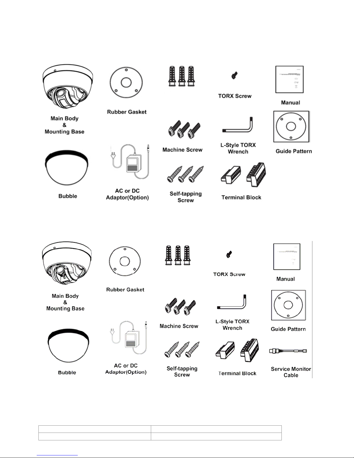
5. Product & Accessories
5.1. (10x/12x Zoom Models)
Plastic Anchor
5.2. Product & Accessories (Variable Focus Lens Model)
Plastic Anchor
5.3. Options
Doc # INS 20Z704T-PZ10 Issue Date: 08/13/2009
Revision: B Page 7 of 40

Ceiling Mount Bracket
Wall Mount Bracket
Doc # INS 20Z704T-PZ10 Issue Date: 08/13/2009
Revision: B Page 8 of 40

6. Parts Name & Functions
Main Unit / Surface Mount Bracket Back of Main Unit
Dome Cover (Bubble) Do not remove protection vinyl from the bubble before
finishing the installation process, thus protecting the bubble
from scratches or dust.
Selectable clear or smoke types.
Surface Mount Base This is used to install the camera directly on the ceiling. After
separating this cover, attach this directly to ceiling.
Camera must be assembled at the last stage.
Fixing Screw Fixes main unit to surface mount bracket.
Cabling Terminal Block During installation, Power, Video, Communication, Alarm Input
cables are to be connected on to this cabling terminal block.
DIP Switch Adjusts camera ID and protocols.
Focus Handle Adjusting the focus lens (FAR/NEAR)
Zoom Handle Adjusting the zoom lens (TELE/WIDE)
Service Monitor Connector User service monitor connector assists setting the camera
angle and focus when installing
DC Level Volume Adjusting the DC iris level
Doc # INS 20Z704T-PZ10 Issue Date: 08/13/2009
Revision: B Page 9 of 40
7. Installation
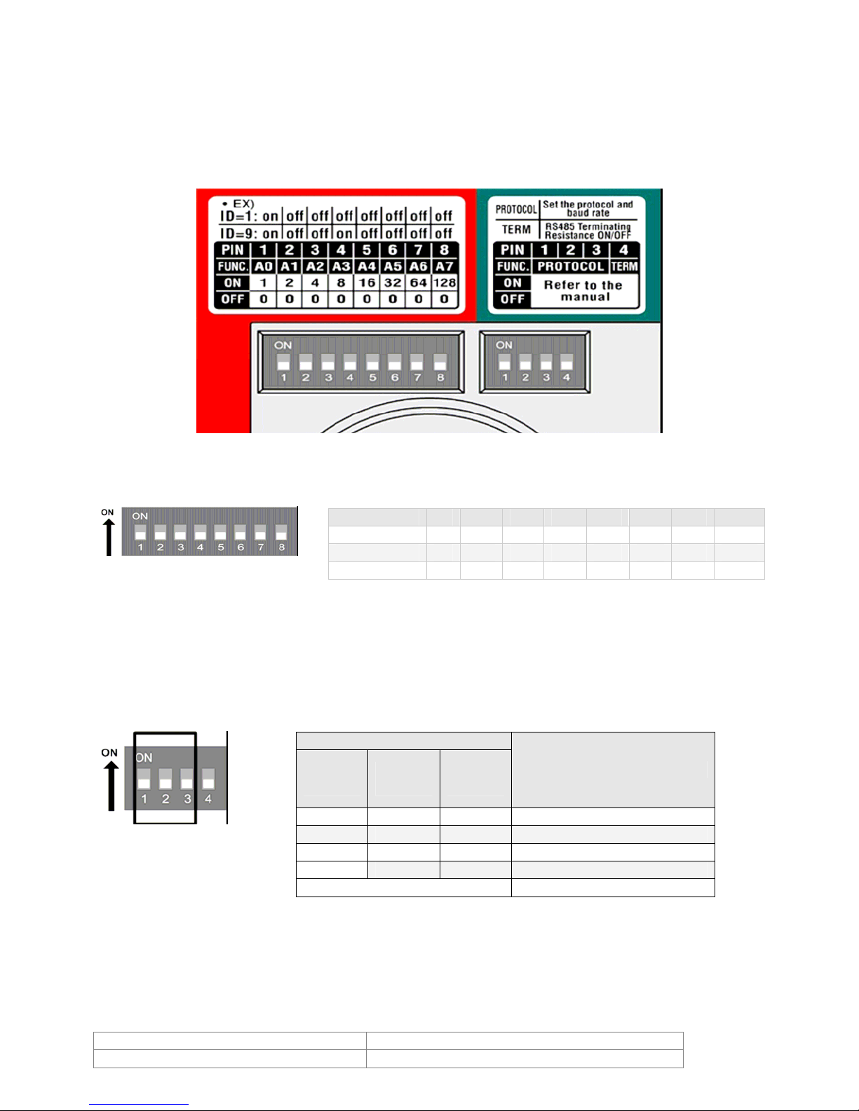
7.1. DIP Switch Setup
Before you install the camera, you should set the DIP switches to configure the camera ID,
communication protocol.
7.1.1. Camera ID Setup
ID number of camera is set using dip switch. The example is shown bellow.
Pin 1 2 3 4 5 6 7 8
ID Value 1 2 4 8 19 32 64 128
The range of ID is 1~255. Do not use 0 as camera ID. Factory default of Camera ID is 1.
If you want to control a certain camera, you must match the camera ID with Cam ID setting
of DVR or Controller.
ex) ID=5 on off on off off off off off
ex) ID=10 off on off on off off off off
7.1.2. Communication Protocol Setup
Select the appropriate Protocol with DIP switch combination.
Switch State
P0
(Pin 1)
If you want to control using a DVR or P/T controller, their protocol must be identical to the
camera. Otherwise, you cannot control the camera.
If you changed camera protocol by changing DIP S/W, the change will be effective after you
reboot the camera.
OFF OFF OFF PELCO-D, 2400 bps
ON OFF OFF PELCO-D, 9600 bps
OFF ON OFF PELCO-P, 4800 bps
ON ON OFF PELCO-P, 9600 bps
P2
(Pin 2)
Others Reserved
P3
(Pin 3)
Protocol
Doc # INS 20Z704T-PZ10 Issue Date: 08/13/2009
Revision: B Page 10 of 40
Factory default of protocol is “Pelco-D, 2400 bps”.
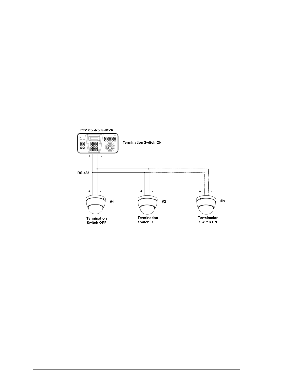
7.1.3. Termination Switch Setting
Termination switch (Pin 4) is used in cases listed below.
• Long-distance communication between the controller and the camera (1-to-1
connection)
When the connecting distance between the two units is especially long,
communication errors may occur due to the impedance of transmission cable. In this
case, set the termination switch of both units to ON.
• Controlling multiple cameras (Multiple connection)
The camera may not operate correctly if multiple cameras are connected and
controlled. In this case, set the termination switch of the controller and the last
connected camera to ON and the switch of other cameras is OFF.
Ex) Using the Terminating Resistance
Doc # INS 20Z704T-PZ10 Issue Date: 08/13/2009
Revision: B Page 11 of 40

7.2. Direct Installation on the Ceiling
1) To pass cables to upside of ceiling,
please, make about 50~60mm hole on the
ceiling panel.
You can use “Guide
Pattern” for the
making holes.
2) Detach the marked part from the rubber
gasket and screw the surface mount bracket
to the ceiling with fixing screws.
3) Wire cables to terminal block and connect
the terminal blocks to main unit.
5) Insert the fixing screw tightly and detach
the protection vinyl from dome cover.
4) Insert the main body into the surface
mount bracket with the molding lines on
each part being aligned and turning
clockwise.
Doc # INS 20Z704T-PZ10 Issue Date: 08/13/2009
Revision: B Page 12 of 40
 Loading...