

Videology 20D779, 21D779 Operation Manual

BOX CONTENTS
1. 20D779 NTSC or 21D779 PAL Color Camera
2. Operation manual
SAFEGUARDS & WARNINGS
1. Read instructions before operating camera.
2. Avoid mounting in direct sunlight.
3. Installation and repair should be undertaken by authorized personnel only.
SOFTWARE CONTROL
Please refer to 20D479/21D479 application
notes for software commands.
Operation Manual
20D779 / 21D779
06/12/07 INS-20D779 REV A
SPECIFICATIONS
Electrical
20D779 (NTSC)
21D779 (PAL)
CCD Sensor
1/3” IL Color CCD
Active pixels (HxV)
768 x 492
752 x 585
Horizontal Resolution
450 TVL CVBS
490 TVL YC
Sensitivit y
0.5 lux
Signal to noise ratio
> 46dB
Gamma
0.45 default or 1 selectable via
dip switch or I2C bus
Gain
Automatic (26 dB default)
Manual / Fixed via software
Synchronization
Internal or H&V lock, Default on
HD/VD Sync out
Back light
compensation
Selectab le via softwa re
White balan ce
Automatic (default)
3 Fixed modes via software
Push to set via hardware or software
8 Fixed speeds via hardware
11 Speeds via software
Shutter speed
Automatic from
1/60 to 1/20,000
Automatic from
1/50 to 1/20,000
Contour enhancement
Selectable Horizontal and Vertical via
software/ dip switch
Mirror mode
On/Off Selectable via software/ dip
switch
Iris signal
Electronic
Iris contr ols
Electronic (default),
fixed shutter speeds (8 values)
Video output
Analog Composite 1Vp-p video (75
Ohms)
Y/C (S-Video)
Power Supply
8-16VDC (12VDC optimal)
Power Consumption
< 2.4W
Environmental
Operating Temp.
-15° ~ 55° C
Storage Temp.
-25° ~ 60° C
Mechanical
Dimensions (WxHxD)
50mm x 60mm x 62.5mm
Lens Mount
CS mount
Accessories
60PR12DC800
12VDC regulated
power supply
60VZZ0030C
Mount with adapter
ring
Optional
Mounting plate - top or bottom
mountable
DC in/ cont rol commun ication kit a vailable on request
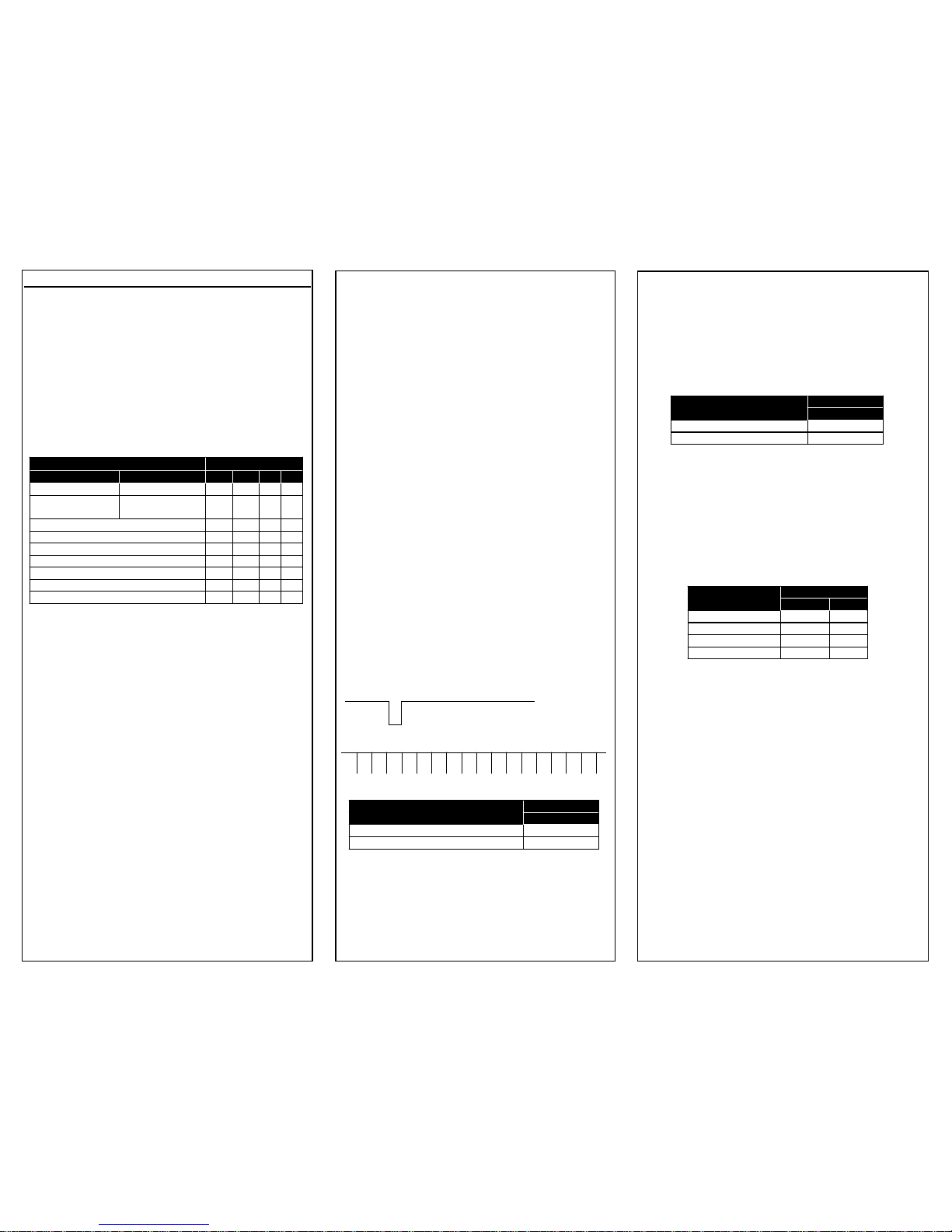
CONNECTORS
CONTROLS
DIMENSIONS
Pin
Function
1
GND
2
+12V DC
3
GND
4
CVBS Out
5
GND
6
Hsync in / HD Out*
7
Vsync in / VD Out*
8
GND
9
10
12C Data
11
12C Clock
12
GND
DC IN / Control
Synchronization mode set by
dip switch 8. See below.
CN3 12 Pin Connector
DIP SWITCHES
Pos’n
Function
1
Electron ic Iris On / O ff
2
S1 - Fixed Shutter Speed
3
S2 - Fixed Shutter Speed
4
S3 - Fixed Shutter Speed
5
Contour Enhancement On/Off
6
Gamma 0.45 / 1
7
AWB / Push
8
S8 - Synchronization Mode
9
S9 - Gain Control
10
Gain Control
11
Mirror Mode On / Off
12
Interlace On / Off
OPERATING INSTRUCTIONS
1.1 Iris Control (Shutter Speed)
The Iris setting is used to control the image intensity in varying lighting conditions. It works by varying the integration time of the camera, which is
measured in fractions of a second, and is analogous
to the shutter speed on a conventional camera. The
shutter speed is set by Dip Switches 1-4, according
to Table 1.
TABLE 1
The flickerless mode is intended for use in environments illuminated by fluorescent lamps. These
lights can cause excessive flickering of the image if
the shutter speed is not set appropriately.
In the Electronic Iris mode, the integration time of
the camera is automatically adjusted according to
the level of illumination.
1.2 Contour Enhancement
The contour enhancement is used to increase the
sharpness of the image, by slightly exaggerating
the boundaries between light and dark areas of the
screen. It may give rise to image artifacts depending upon the scene content, and the appropriate
setting is best established by experimentation.
The contour enhancement is enabled via Dip Switch
#5 (On).
1.3 Gamma
The gamma control defines the overall transfer
function of the camera. That is the relationship
between the incident light intensity and the
amplitude of the video output signal. A gamma of
1 defines a linear relationship, and is best suited
for use with image capture devices. A gamma
setting of 0.45 is used to offset the non-linear
response of the phosphors used in video monitors, and this should be used when viewing the
camera on such a monitor.
The gamma is selected Via software control or
Dip Switch #5 (ON = .45, OFF =1)
1.4 Synchronization
There are synchronization modes, selectable via
Dip Switches 7 and 8.
In mode 1, the camera timing will be derived
from the internal crystal or lock to externally supplied H and V pulses (Master Mode).
In mode 2, the camera timing will sync. to external H and V pulses. See Application note “APN20D479”, section 4.3 for more information on
external synchronization.
1.5 White Balance
The camera has 2 white balance modes. AWB (auto
white balance) allows the camera to adjust white
balance based on the scene.
Push to set (PUSH) sets the white balance to fixed
values determined at the time the button is
pushed.
1.6 Gain Control
The camera can be set to Automatic Gain Control
(Dip Switches 9 and 10 Off) whereby the gain of
the camera will be varied in response to changes in
the average level of illumination.
Alternatively, the gain can be set to one of three
fixed values as defined in the table below.
1.7 Mirror Mode
This option is used to perform a mirror inversion of
the camera image, and is used when the camera is
viewing the object via an external mirror. The mirror mode is enabled by setting Dip Switch #11 to
the ON position.
1.8 Non Interlace Mode
In the normal mode, the camera outputs thirty full
frames per second. Each frame is comprised of
two interlaced fields, each containing 262 lines.
The presence of the interlace can cause problems
when capturing images of moving objects, due to
the temporal separation of the fields. In the non
interlaced mode, the camera outputs two identical
fields per frame. In the non interlaced mode, the
vertical resolution of the image is reduced by a factor of 2.
Shutter Speed
Dip Switch
20D779
21D779
1 2 3
4
1/60 sec. (max)
1/50sec. (max)
Off
On
On
On
1/100 sec.
( Flickerless)
1/120 sec.
( Flickerless)
Off
On
On
Off
1/250
Off
On
Off
On
1/500
Off
On
Off
Off
1/1000
Off
Off
On
On
1/2000
Off
Off
On
Off
1/10000
Off
Off
Off
On
1/20000
Off
Off
Off
Off
Electronic Iris
On x x
x
Dip Switch
Sync Mode
8
Mode 1. Master (Internal Sync.)
Off
Mode 2. Slave
On
Dip Switch
White Balance Mode
7
Mode 1. AWB
On
Mode 2. PUSH
Off
Dip Switch
Gain Setting
9
10
AGC On
On
On
0 dB
On
Off
6 dB
Off
On
12 dB
Off
Off
06/12/07 INS-20D779 REV A
 Loading...