

Page 1
MODELS
20C40XW-1
21C40XW-1
Note: While you can start using the Pixim® camera "right
out of the box”, most of the time, the default setup isn't
optimum for any one particular environment. It's best to
read the manual thoroughly and manually fine tune the
camera to your particular in door/outdoor setting needs to
get the best picture.
PRODUCT FEATURES
Camera Features
• 1/3" CMOS Pixim®
Seawolf® progressive
scan sensor
• /3” Pixim CMOS
progressive scan
• 690 TVL resolution
• Low 0.1 lux sensitivity
• Dynamic range to
120dB
• Global shutter
• Digital video output
(optional models)
• 3D motion adaptive
noise reduction (DNR)
Features available via
OSD control board
(60ZRC10)
• Motion de t ection
• Day/night mode
• Digital pan/tilt/zoom
(8x)
• Digital slow shutter
(DSS)
• Push to set white
balance
• Sens-up (2x-32x)
• NTSC/PAL selectable
• RS-485 (optional)
CONTACT INFORMA TIO N
For technical assistance with this product, please contact
the supplier from whom the product was purchased.
Please visit our website at: http://www.videologyinc.com
VIDEOLOGY IMAGING SOLUTIONS is an ISO 9001
registered video camera developer and manufacturer
serving industrial, machine vision, biometric, security,
and specialty OEM markets.
Videology designs, develops, manufactures, and
distributes video, image acquisition, and display
technologies and product s to OEMs worldwide.
For OEM inquiries:
North/South America
37M Lark Industrial Parkway
Greenville, RI 02828
Tel: (401) 949
-5332
Fax: (401) 949
-5276
Europe
Neutronenl aan 4
NL
-5405 NH Uden,
Netherlands
Tel: +31 (0) 413 256 261
Fax: +31 (0) 413 251 712
03/21/13 INS-20C40XW-1 Rev C
How to Use the Camera
Settings
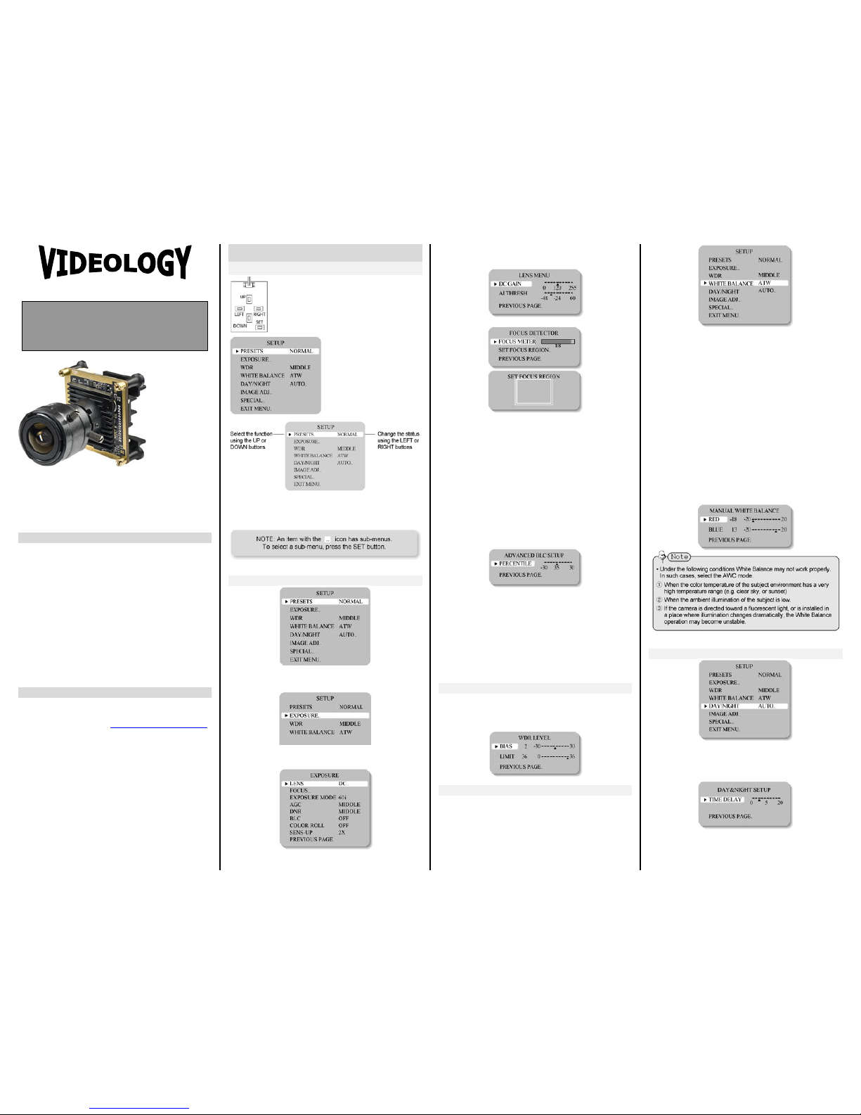
Settings can be made using the 5 buttons
located on the OSD control board.
1. Press the SET button. Settings can now
be made. The SETUP menu is displayed
on the monitor.
2. Select a menu item
from the list available
by using the UP and
DOWN buttons.
• Functions are selected
using up and down
buttons.
• The selected position is
displayed in blue.
3. Set up a selected item by using the Left and Right
buttons.
4. To finish and save the settings, select 'EXIT' and press
the SET button.
PRESETS
• NORMAL default color balance
• INDOOR fluorescence color balance
• OUTDOOR outdoor color balance
When the SETUP menu screen is displayed, select
‘EXPOSURE’ by using the Up and Down buttons so that
the arrow indicates ‘EXPOSURE’.
• LENS: Using this function, you can control the screen
brightness.
o DC / Manual : Select Lens Type
• FOCUS : To adjust the DC and VIDEO lens focus
• EXPOSURE MODE: To select the number of fields and
number of exposure cycles.
o 60i /30p selectable
• AGC (AUTO GAIN CONTROL): In th e dark situation,
the higher the gain level, the brighter the screen but
the higher the noise.
o OFF / LOW / MIDDLE / HIGH selectable
• DNR (Digital Noise Reduction): The level of
background noise in low light decreases automatically
as the level of gain changes.
o OFF / LOW / MIDDLE / HIGH selectable
• BLC: To optimize the scene when there is a strong
backlight behind the object.
o ON / OFF selectable
• COLOR ROLL: To control a detect or t hat finds color
fluorescent roll.
o OFF / LOW / MIDDLE / HIGH selectable
• SENS-UP: When it is night or dark, the camera
automatically detects the light leve l and maintains a
clear picture if this mode is activated.
o 2X, 4X, 8X, 16X, 32X, 64X
o OFF: Deactivates the SENS-UP function.
WDR
• WDR: When the image has simultaneous bright and
dark areas, the Wide Dynamic Range makes both
areas distinct.
o LOW / MIDDLE / HIGH / USER selectable
WHITE BALANCE
Use the White Balance function to adjust the screen
colors.
1. Position the c u rs or to point to WHITE BAL on the
SETUP menu screen, select using the Up and Down
buttons.
2. Select the desired mode using the Left and Right
buttons.
*Select one of the following 5 modes, as appropriate.
• ATW: The ATW mode continuously monitors.
• INDOOR: Select when the color temperature is
between 4000˚K and 8500˚K
• OUTDOOR: Select when the color temperature is
between 2000˚K and 11000˚K
• AWB: To obtain the optimum state under the current
luminance levels, direct the camera to point toward a
sheet of white paper and press the SET button. If the
environment changes, including the light source, the
white balance will require re-adjustment.
• MANUAL: Select to "fine-tune" the White Balance
manually. Set White Balance first using the ATW or
AWB mode. Afterwards switch to MANUAL mode, finetune the White B alance and then press the SET
button.
DAY/NIGHT
• AUTO: This camera has a function which
automatically changes to the appropriate mode
according to lighting levels. To set up the switching
time and switching speed for the AUTO mode press
the SET button.
• COLOR: The picture is displayed in color.
• B/W: The picture is always displayed in black and
white.
Instruction Manual
WDR Day/Night
Color Board Camera
IMAGING SOLUTIONS INC.
Original Equipment Manufacturer
20C406W-1 shown with
optional M
-14 lens
Page 2
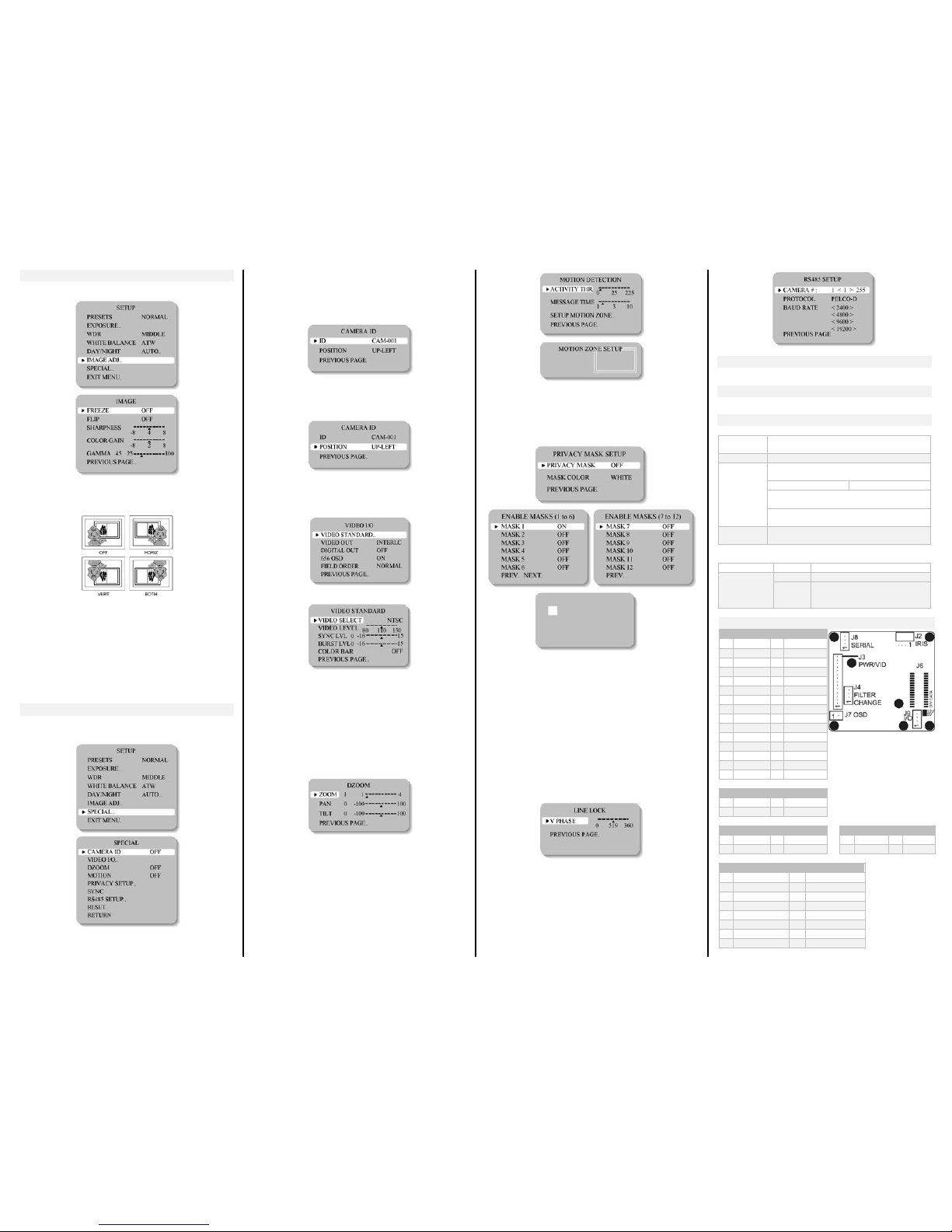
IMAGE ADJUSTMENT
When the SETUP menu screen is displayed, select 'IMAGE
ADJ.' using the Up and Down buttons.
• FREEZE: View still pictures.
o OFF / ON selectable
• FLIP: OFF / HORIZ / VERT / BOTH selectable
• SHARPNESS: The outline of the video image becomes
cleaner and more distinctive as the level of
SHARPNESS increases. If the level goes up
excessively, however, it may affect the video image
and generate noise.
o The available range of level is -8 ~ 8
• COLOR GAIN: To control the color level in the video.
o The available range of level is -8 ~ 8
• GAMMA : Use rs can change the gamma setting
between 25 and100
SPECIAL
When the SETUP menu screen is displayed, select
'SPECIAL' by using the Up and Down buttons so that the
arrow indicates 'SPECIAL'.
• CAMERA ID: User can enter a unique name for the
respective camera. The maximum length of the ID is
ten characters.
o You can choose the ON and OFF with the selector.
If you select ON, the entered camera ID is
displayed at the selected position in the video
picture (normal operati on).
o Please select the setup button while in ON mode.
o Select the desired position with the selector.
1. Move the cursor t o th e letter required by using the
Set-Up button.
2. Select an ID from A, B~Y, Z, a, b~y, z, 0, 1~8, 9 by
using the LEFT and RIGHT buttons.
3. Repeat the above steps until the ID is complete.
1. Select the position where the ID is to be displayed by
using the LEFT and RIGHT buttons.
• VIDEO I/O: M ove the cursor to select the video
system.
o VIDEO STANDARD: You can control NTSC / PAL,
Video level, Sync level, Burst level.
o VIDEO OUT: Interlace/ Progressive Video
selectable.
o DIGITAL OUT: Digital output ON/OFF selectable.
o 656 OSD: Digital output OSD ON/OFF selectable.
o FIELD ORDER: Normal/Reverse Field selectable.
• DZOOM: Digital P/T/Z is used to create a zoom lens
effect.
Zoom Factor (1X to 4X), Pan (±100%, center of image
can be moved to left and right edges of screen), Tilt
(±100%, center of image can be moved to top and
bottom edges of screen)
● MOTION: This product has a feature that allows you to
observe movements of obje c t s on t he screen; hence a
single individual can conduct supervision efficiently. The
camera detects an object's movement by sensing
disparity of outline, and level of brightness and color.
o White: MOTION ZONE Position movemen t
Green: MOTION ZONE Size enlargement
Red: MOTION ZONE Size reduction
o For MOTION ZONE Confirm, long press SET bu tt on
• PRIVACY SETUP: Hide an area you want to hide on
the screen.
o White: PRIVACY-ZONE Position movement.
o Blue: PRIVACY-ZONE Size enlargement or
reduction.
o For PRIVACY-ZONE Confirm, long press SET button.
• SYNC: Tw o synchronization modes are availa ble,
INTERNAL and EXTERNAL LINELOCK. In LINE-LOCK
mode, it synchronizes the video signal between
cameras without a synchronous generator. The linelock synchronization is only used in areas of 60Hz
(NTSC)/ 50Hz (PAL).
o INT: Internal synchronization
o LL: External line-lock synchronization
If 'LL' is selected, it can be adjusted to the desired
phase.
Press the SET button.
o Adjust to the desired phase from 0 to 360.
• RS485 SETUP: This function sets up the camera
communication status when controlling the camera
through an external control d e vice.
RESET
Resets the camera settings to the factory defaults.
EXIT MENU
Saves all the setting menus and then exits.
SPECIFICATIONS
MECHANICAL
Dimensions
WxHxD
42mm x 42mm x 18.2mm
(1.65” x 1.65” x 0.71”)
Weight
43g (1.51oz)
Lens Mounts
Replace “X” in model number with desired
lens mount option:
5=Metal M-12 Boa rd
6 = Metal M-14 Board
Example: Change 20C40XW to 20C405W to
select an M-12 Board Mount.
Change 20C40XW to 20C406W to select an
M-14 Board Mount.
Lens
See our lenses at:
www.videologyinc.com/lenses
ACCESSORIES
Included
BNC/power cable
Optional
60ZRC10
OSD control board
60C1001
30 pin - 20 pin digital output
cable (digital camera only
20/21C40XWD)
PIN ASSIGNMENT
J6 (30 PIN) Digital Signal
1 16
GND 2
17
DV3 3
18
DV9 4
19
DV4 5
20
DV8 6
21
DV5 7
22
DV7
8
RXDV
23
GND 9 DV0
24
DV6
10
TXDV
25
RESET
11
DV1
26
GND
12
GND
27 13
DV2
28 14
DVCLK
29 15
GND
30
J2 (4 PIN) IRIS
1 DMP+ 3 DRV+ 2
DMP- 4 DRV-
J8 (4 PIN) PELCO-D
J9 (4 PIN) I/O
1
VCC3V3
3
TX 1
UTP+ 3 GPIO00
2
RX 4 GND 2
UTP- 4 GPIO01 J3 (15 PIN) MAIN CONNECTOR
1 VIDEO 8 KEY_DOWN
2
VIDEO_GND
9
KEY_UP 3
DC12V
10
KEY_SET
4 GND
11
KEY_RIGHT
5 LINE-LOCK
12
KEY_LEFT
6 GND
13
M/D_OUT
7 EXTRA_VIDEO
14
IRIS SIGNAL
15
D/N_SEL
 Loading...