

VideoLogix Proteus-V User Manual

1
Proteus-V
User Manual
Version V1.7
June 24, 2019

2
TABLE OF CONTENTS
GENERAL OVERVIEW ................................................................................................................................................................................................................... 4
TYPICAL INTERCONNECT DIAGRAM ...................................................................................................................................................................................... 4
GLOSSARY TERMS ......................................................................................................................................................................................................................... 5
COMMUNICATION ......................................................................................................................................................................................................................... 5
COM PORTS ...................................................................................................................................................................................................................................... 5
COM PORTS: PINOUTS ....................................................................................................................................................................................................................... 5
COM PORTS: BAUD RATES................................................................................................................................................................................................................. 5
COM PORTS: DEVICE TYPES .............................................................................................................................................................................................................. 6
COM PORTS: CONFIGURATION .......................................................................................................................................................................................................... 6
CSV FORMATS .................................................................................................................................................................................................................................. 7
CSV SENTENCE STRUCTURE.............................................................................................................................................................................................................. 7
INTERFACE TO COM1 ......................................................................................................................................................................................................................... 8
ETHERNET PORT ................................................................................................................................................................................................................................ 8
USB DEVICE PORT ............................................................................................................................................................................................................................. 8
USB HOST PORTS............................................................................................................................................................................................................................... 8
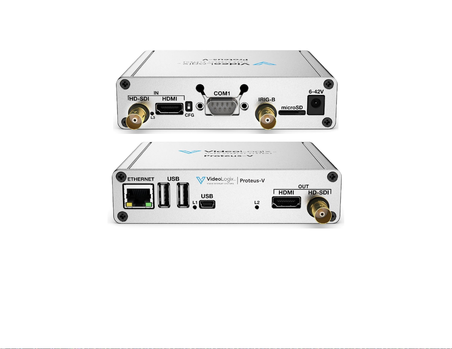
VIDEO INPUT & OUTPUT .............................................................................................................................................................................................................. 9
VIDEO FRAME RATES ....................................................................................................................................................................................................................... 10
VIDEO DELAY .................................................................................................................................................................................................................................. 10
IRIG INPUT ...................................................................................................................................................................................................................................... 10
STORE CONFIGURATION ........................................................................................................................................................................................................... 11
LOAD CONFIGURATION ............................................................................................................................................................................................................. 11
FEATURES ....................................................................................................................................................................................................................................... 12
INSERT TEXT .................................................................................................................................................................................................................................... 12
INSERT GRAPHICS ............................................................................................................................................................................................................................ 14
INSERT VARIABLES FROM ANY CSV SENTENCE ................................................................................................................................................................................. 16
INSERT VARIABLES FROM ANY UNSUPPORTED NMEA SENTENCE ...................................................................................................................................................... 16
INSERT GPS DATA ............................................................................................................................................................................................................................ 19
INSERT NMEA DATA ......................................................................................................................................................................................................................... 21
INSERT TIME, DATE (IRIG, GPS, RTC, ATC) ........................................................................................................................................................................................ 22
ADD MILLISECOND COUNTER TO IRIG, GPS, RTC TIME ...................................................................................................................................................................... 23
INSERT QUADRATURE OR SIMPLE COUNTERS ................................................................................................................................................................................... 24
INSERT AIRCRAFT SITUATION AWARENESS ..................................................................................................................................................................................... 28
INSERT ROV SITUATION AWARENESS .............................................................................................................................................................................................. 30
INSERT COUNT UP TIMER ................................................................................................................................................................................................................. 32
INSERT SLIDERS ............................................................................................................................................................................................................................... 33

3
INSERT COMPASS ............................................................................................................................................................................................................................. 35
PROTEUS COMMANDS ................................................................................................................................................................................................................ 36
TRANSMIT A COMMAND SCRIPT ...................................................................................................................................................................................................... 36
PROTEUS REGISTERS ................................................................................................................................................................................................................. 37
SPECIFICATIONS .......................................................................................................................................................................................................................... 38
MAXIMUM INPUT VOLTAGE ............................................................................................................................................................................................................. 38
INPUT CONNECTOR .......................................................................................................................................................................................................................... 38
ENVIRONMENTAL ............................................................................................................................................................................................................................ 38
WEIGHT & DIMENSION .................................................................................................................................................................................................................... 38
FRONT PANEL LED ........................................................................................................................................................................................................................... 38
PCB DIMENSION .............................................................................................................................................................................................................................. 39
ENCLOSURE DIMENSION .................................................................................................................................................................................................................. 41
APPENDIX A – KEYBOARD COMMANDS ............................................................................................................................................................................... 42
PS2 KEYBOARD COMMANDS ................................................................................................ ................................................................ ............................................ 42
KEYBOARD SHORTCUTS .................................................................................................................................................................................................................. 42
APPENDIX B – UPDATING FIRMWARE ................................................................................................................................................................................... 43
APPENDIX C – INSTALL RENESAS FLASH PROGRAMMER ............................................................................................................................................. 45
APPENDIX D – IMAGES................................................................................................................................................................................................................ 46
JPG ................................................................................................................................................................................................................................................. 46
PNG ................................................................................................................................................................................................................................................ 46
LOCATION ....................................................................................................................................................................................................................................... 46
APPENDIX E – CREATE CUSTOM FONTS ............................................................................................................................................................................... 47
APPENDIX F – TERMINAL BLOCKS ......................................................................................................................................................................................... 48
APPENDIX G – REGISTER DESIGNATION .............................................................................................................................................................................. 49
4
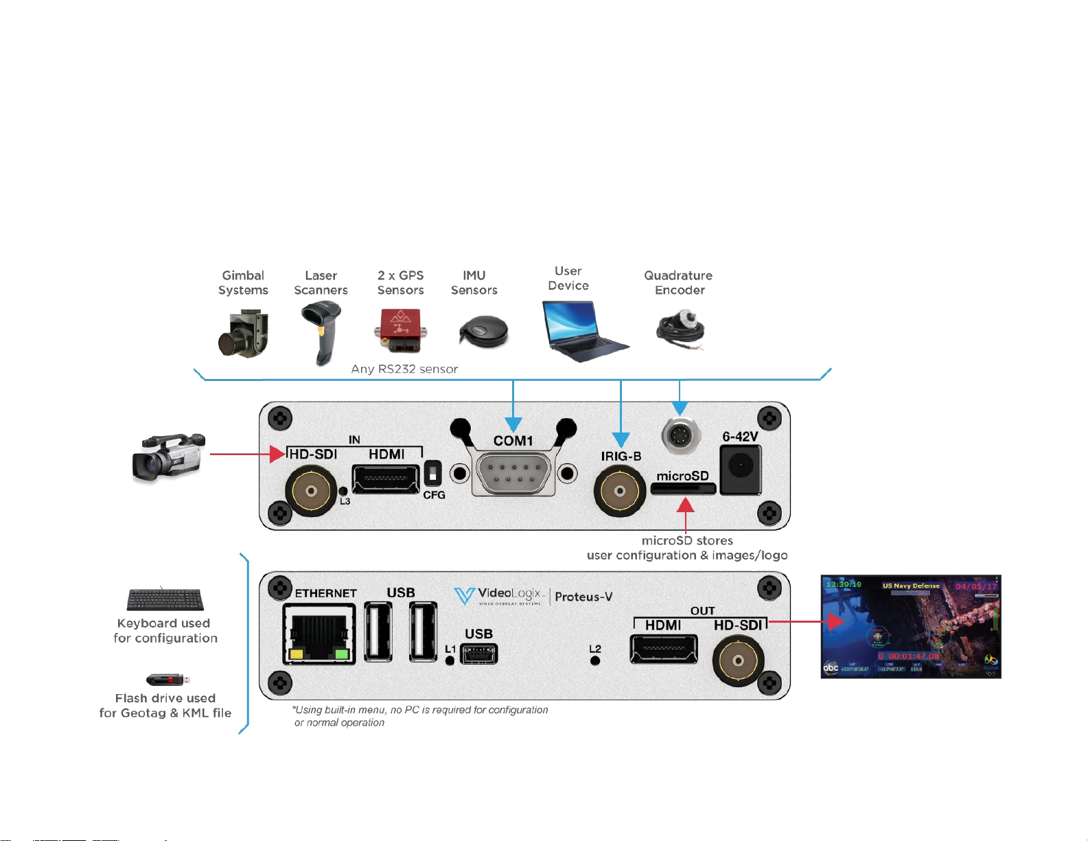
GENERAL OVERVIEW
Video Overlay is a method by which computer-generated images are superimposed on video. Properly transformed images appear as if they are an
integral part of the scene without impeding the video of the actual environment. Proteus provide2s professional, scientific and industrial users with the
capability to overlay crisp and clear texts, graphics and telemetry generated information into an incoming HD & SD video in real time. Proteus accepts
video in HD-SDI, HDMI. It generally, does not need to be connected to a computer for normal operation.
TYPICAL INTERCONNECT DIAGRAM
Diagram below illustrates a few the possible applications.
5
GLOSSARY TERMS
Term
Definition
SCS
Software Communication Specification
CSV
Comma Separated Variables
CAN
Controller Area Network
TB
Terminal Block
UM
User Manual
COM
RS232 Communication port
GPS
Global Position System
COMMUNICATION
COM PORTS
Proteus provides 2 x serial ports (COM1 & COM2) for communication with the external devices:
COM PORT
Alternative 1
Alternative 2
COM1
RS232 (Rear Panel DB9)
-
COM2
RS232 (Internal TB: J54 & J16)
CAN (Internal TB: J48)
TB = Terminal Block
COM PORTS: PINOUTS
COM PORT
Connector
Modes
Pin assignments
COM1
DB9
RS232
DB9:
1=RX, 3=TX, 5=GND
COM2
Internal
RS232
CAN
J54:
J48:
1=RX, 2=GND, 3=TX
1=GND, 2=CAN-, 3=CAN+
COM PORTS: BAUD RATES
• COM ports are configured for N, 8, 1 and can be set to the baud rates 4800, 9600, 19200, 38400, 57600, 115200
6
COM PORTS: DEVICE TYPES
COM ports can be interfaced to various sensors/devices. Table below shows the current list and their corresponding Device Type setting.
Attach Sensor/Device
Corresponding Device Type
CSV (Comma Separated Variable) ASCII Sentence
CSV1, CSV2, CSV3 (See CSV formats for more detail)
All NMEA-0183 compatible devices i.e. GPS Modem, Sounder, etc.
CSV1
ProteusApp
CSV1
PuTTY or similar program
CSV1
Vector NAV IMU
VectorNav
General Dynamic CINEFLEX
CINEFLEX
Smart Micro Radar
ALTIMETER
APOS for HIPAP system (KONGSBERG)
SIMRAD
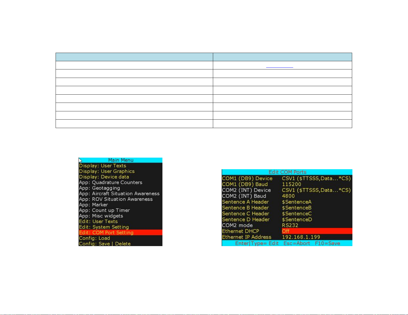
COM PORTS: CONFIGURATION
Press F9 to display the Main Menu. Follow Figure 1-Figure 2 to configure COM ports for desire baud rate & device type as well as Ethernet port.
Figure 1
Figure 2
7
CSV FORMATS
Many sensors transmit ASCII sentence also known as Comma Separated Variables (CSV). Proteus supports 4 different ASCII sentences:
CSV Format
Sentence includes
Sentence Structure
Example
CSV1
$Header, Data…, Checksum
$TTSSS,VAR1,VAR2,VAR3,...VARn*CS
$MYHEADER,45,315,200,100*XX
CSV2
$Header, Data…
$TTSSS,VAR2,VAR3,...
$MYHEADER,45,315,200,100
CSV3
$Data...
$VAR1,VAR2,VAR3,...
$45,315,200,100
CSV4
Data…
VAR1,VAR2,VAR3,..
45,315,200,100
Upon reception of a CSV sentence and successful confirmation of the sentence header $TTSSS (only CSV1), Proteus parses the sentence. Parsed variables
(VAR1 ... VAR2) are sequentially stored in Register # {52-63}, {65-72}, {74-81}. Any widgets linked to these registers will automatically get updated.
CSV SENTENCE STRUCTURE
$
Signifies start of the sentence.
TTSSS
Sentence unique header. Follow Figure 1-2 to define $TTSSS header
VARn
Each sentence contains multiple data fields (VARn) delimited by commas.
*
The asterisk serves as checksum delimiter.
CS
The checksum field contains two ASCII characters which indicate the hexadecimal value of the checksum.
CSV sentence vary in length, but each VAR is limited to 40 characters or less.
The checksum field is the last field in a sentence and follows the checksum delimiter character “*”. The checksum is the 8-bit exclusive OR of all characters
in the sentence, including “,” delimiters, between but not including the “$” and the “*” delimiters. The hexadecimal values of the most significant and least
significant 4 bits of the result is converted to two ASCII characters (0-9, A-F (upper case)) for transmission. The most significant character is transmitted
first. Example: $GPGLL,5057.970,N,00146.110,E,142451,A*27<CR><LF>
In C checksum computation would be written as:
char sentence [] = “GPGLL,5057.970,N,00146.110,E,142451,A”;
int i;
char checksum = 0;
for ( i = 0; i < strlen(sentence); i++)
checksum ^= sentence[i];
Although not recommended, for CSV1 type sentences, checksum computation can be bypassed by replacing CS with XX.

8
INTERFACE TO COM1
COM1 (DB9) is configured as DTE (PC) i.e. RX=Pin2, TX=Pin3. Thus, sensors such as GPS can be directly connected to the DB9 without the need for NULL
modem cable. However, a NULL modem cable is required to interface Proteus to PC.
ETHERNET PORT
This port can be used to send remote commands defined in SCS (Software Communication Specification).
• 10M/100M auto sensing network interface
• Networking: Static or DHCP IPv4 addressing
• Subnet Mask: 255.255.255.0
• Default Gateway: 0.0.0.0
• UDP protocol. Port 9999
Follow Figure 1-Figure 2 to configure network interface.
Following any change to the DHCP setting, power must be recycled for the change to take effect. Proteus’s IP address can be viewed by pressing Alt-H.
USB DEVICE PORT
This port is used to upgrade the internal firmware.
USB HOST PORTS
Proteus has 2 USB host ports. Typical devices connected to these ports are USB keyboard and USB Flash drive.
9
VIDEO INPUT & OUTPUT
Proteus provides the following video input & output:
• SDI (HD & SD)
• HDMI (HD & SD)
Proteus does not support HDMI video with HDCP. It can only process one video input at a given time. If more than one input is connected at the same
time, Proteus selects a video input based on the following priorities:
1. SDI
2. HDMI
Proteus does not scale video and the output resolution follows the input. Proteus provides simultaneous video outputs.

10
VIDEO FRAME RATES
Proteus is compatible with the following video formats:
NTSC 480i @
60 Hz
PAL 576i @
50 Hz
720p @
50 / 59.94 / 60 Hz
1080i @
50 / 60 Hz
1080p @
23.98 / 24 / 25/ 29.97/ 30 Hz
1080PsF @
23.98 / 24 Hz
VIDEO DELAY
All OSD functions are superimposed into the video "on-the-fly." As a result, there is no degradation in video quality and the delay from the video input
to the video output is < 290 nsec.
IRIG INPUT
This input can be used to input an external unmodulated IRIG-B signal. Proteus can decode IRIG-B time & date code.
11
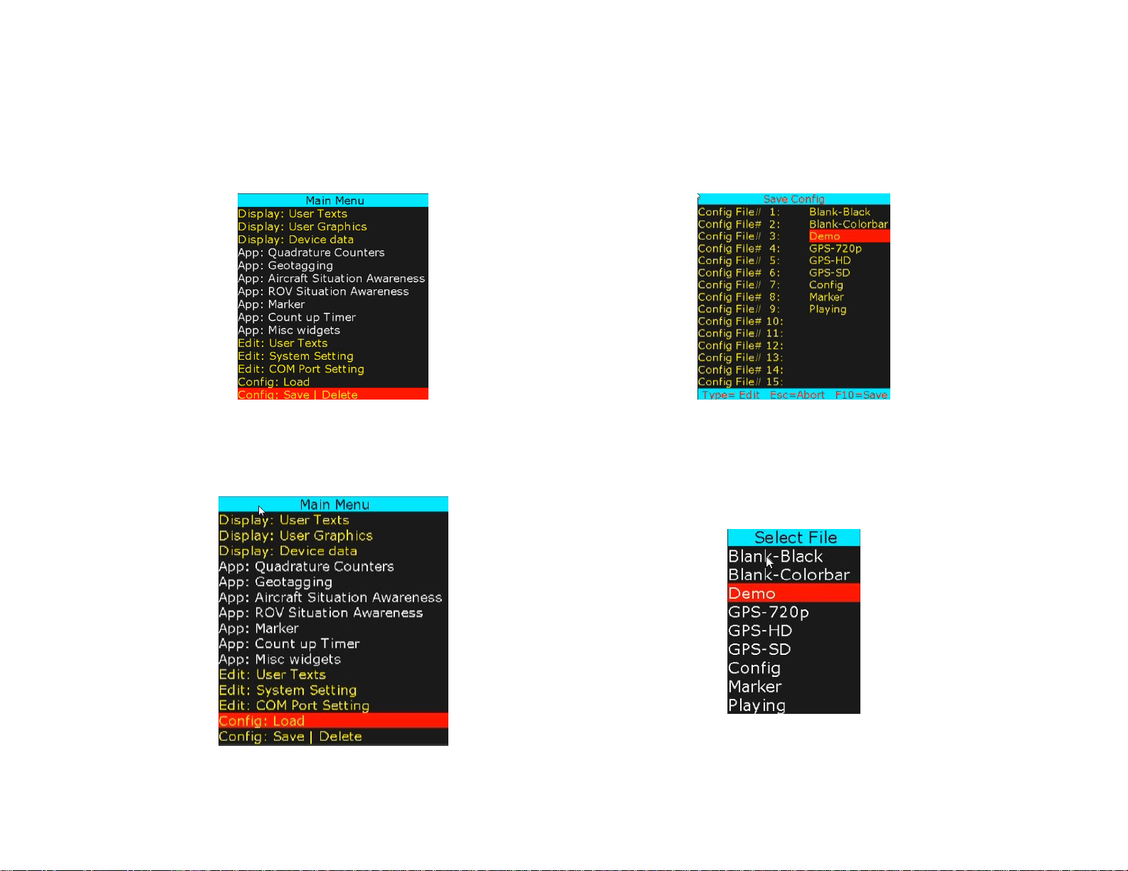
STORE CONFIGURATION
Proteus stores 16 different configurations. Follow figures below to save your configuration.
To save, select a pre-existing file (overwrite) or type in a new file. When ready, press F10 to save.
To delete a configuration file, select file and press Ctrl + Alt + F10.
LOAD CONFIGURATION
Follow figures below to load a pre-stored configuration.
12
FEATURES
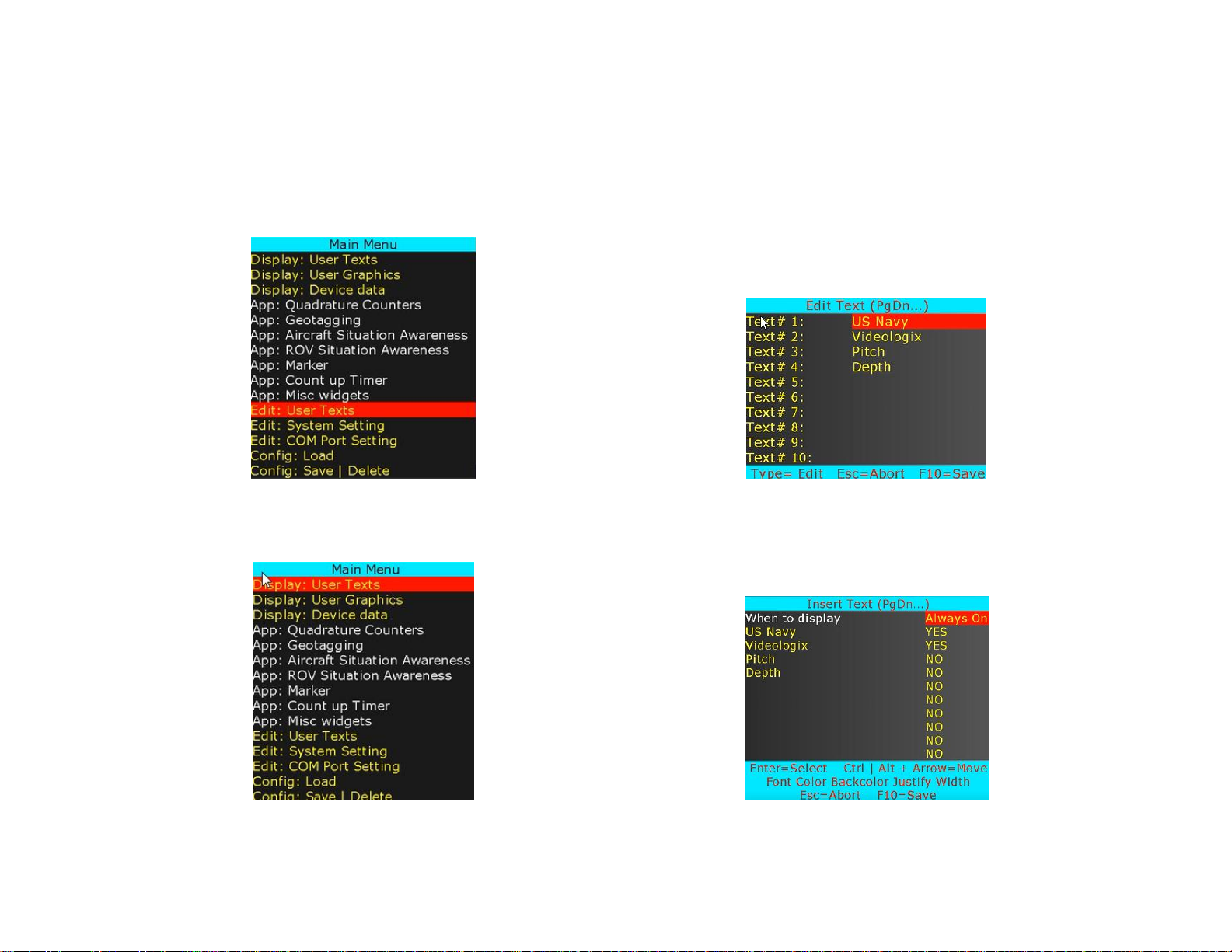
INSERT TEXT
Up to 96 user texts can be stored.
Press F9 to display Main Menu. Follow Figure 3-Figure 4 to enter/edit user texts.
Figure 3
Figure 4
Follow Figure 5-Figure 6 to insert and/or format text.
Figure 5
Figure 6
13
Use shortcuts to change text attributes: Font select, text Color, ↕↔ text position, text Background, field Width and text Justification.
“When to display” allows user to select when text is displayed. Options are: at power up or when function key F1..F7 is pressed.
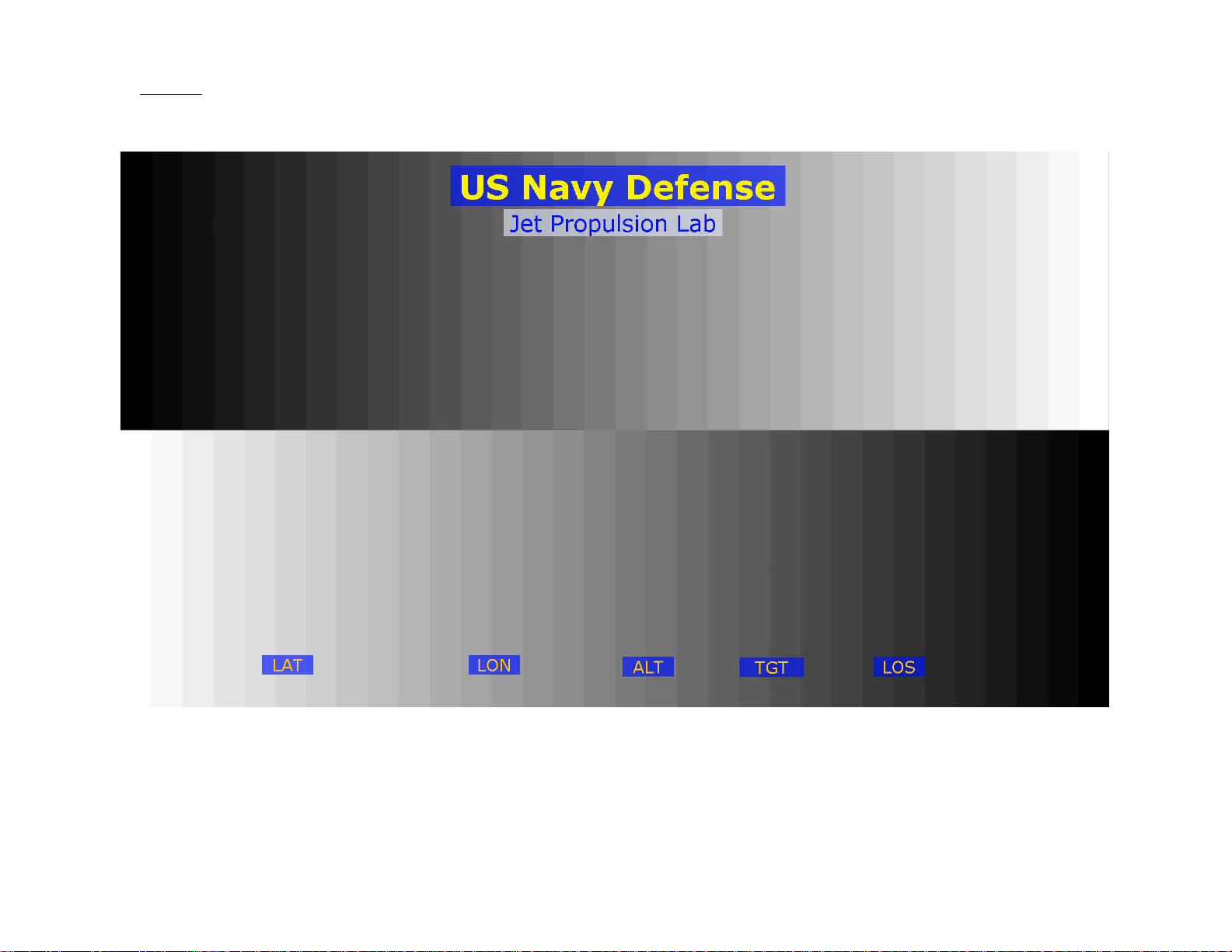
Once complete, text overlay should appear as shown in Figure 7.
Figure 7
14
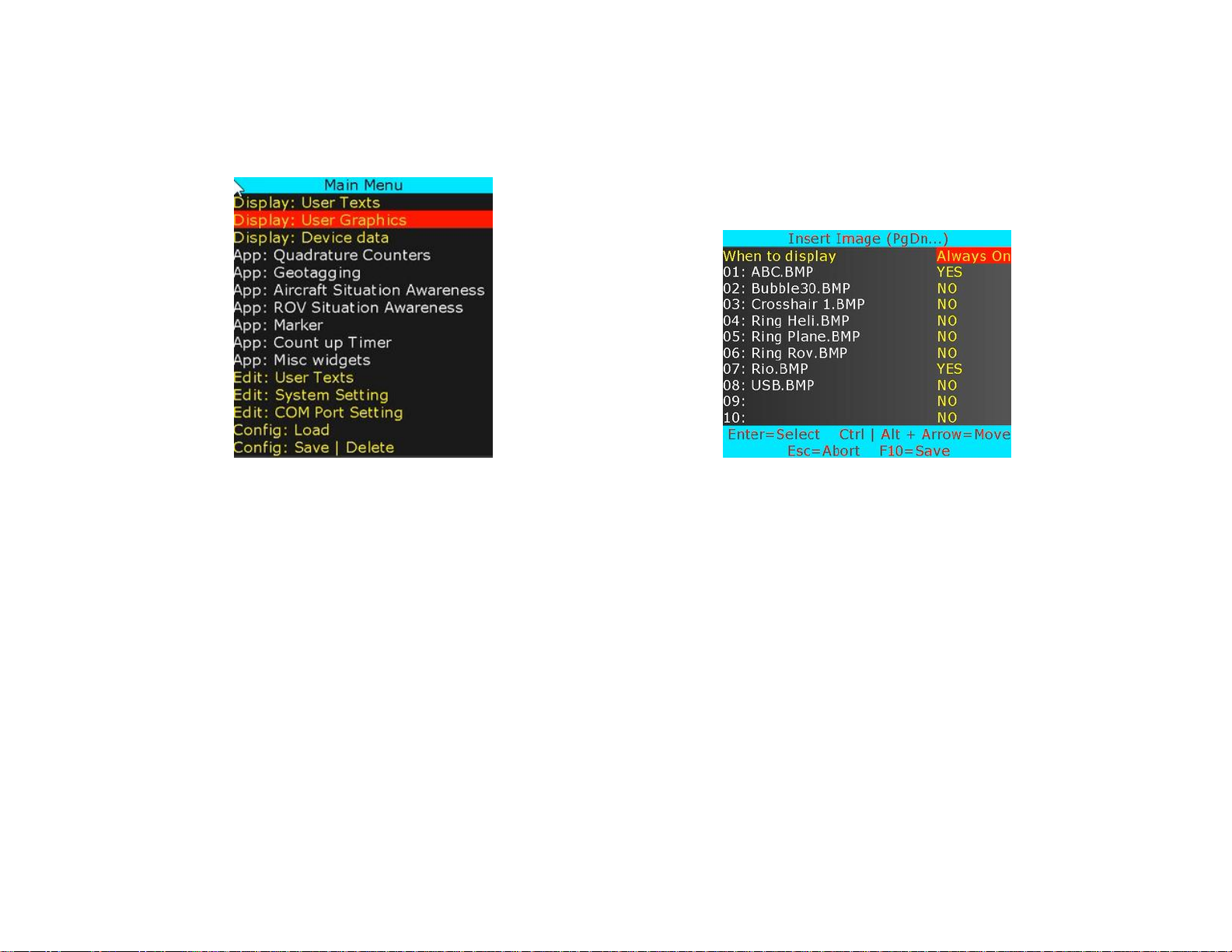
INSERT GRAPHICS
Up to 96 PNG/JPG images can be stored.
Press F9 to display Main Menu. Follow Figure 8 and Figure 9 to insert images.
Figure 8
Figure 9
While in Figure 9, use ↕ to select a desire image and use Ctrl + ↕↔ to position the image on screen.
“When to display” allows user to select when image is displayed. Options are: At power up or when function key F1..F7 is pressed.
Once complete, graphics images should appear as shown in Figure 10.
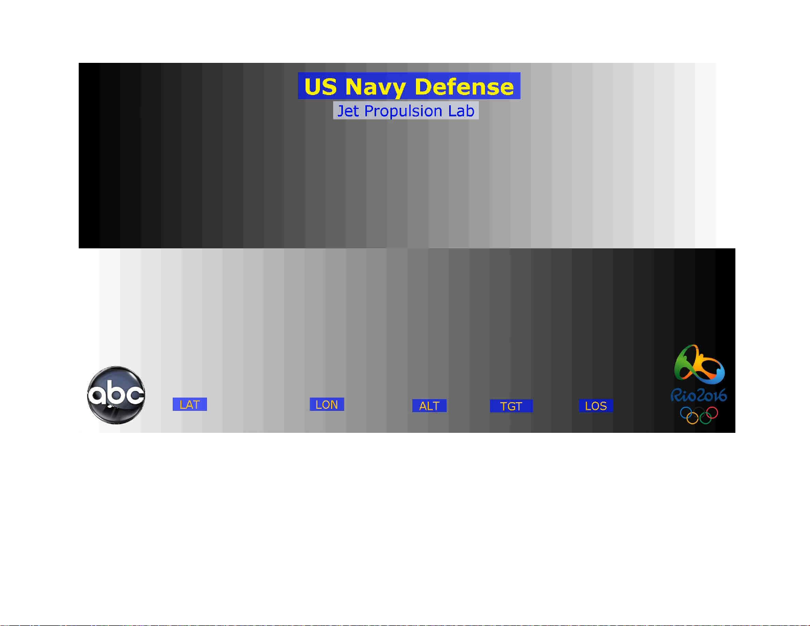
15
Figure 10
16
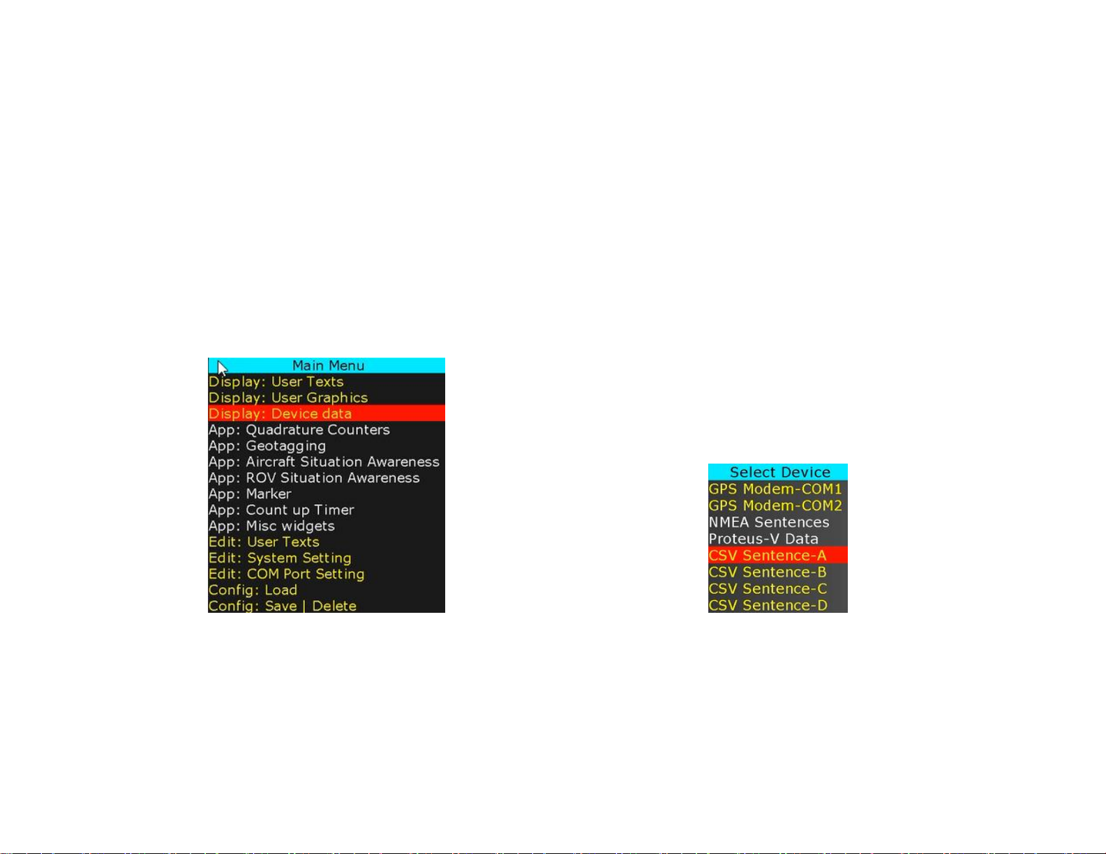
INSERT VARIABLES FROM ANY CSV SENTENCE
INSERT VARIABLES FROM ANY UNSUPPORTED NMEA SENTENCE
Configuring a COM port as “CSV*” allows Proteus to receive an ASCII sentence or any NMEA sentence. Upon reception of a sentence, Proteus parses the
sentence. Parsed variables (tokens) are sequentially stored in Registers # 40-87. Any widgets linked to these registers will automatically get updated.
Example:
The sentence must start with a unique header that matches the user defined value. Follow Figure 1-2 to define your unique header.
$HeaderA,1,22,333,4444,55555,666666,7777777,88888888,999999999,1234,2345,3456*XX
Proteus can be configured to receive and parse up to 4 unique CSV sentences each containing 12 variables.
Follow Figure 1-Figure 2 to configure COM port for desire baud rate and sentence headers
Follow Figure 11-Figure 16 to insert any variable in the CSV sentence.
Figure 11
Figure 12
 Loading...