

Page 1

1
PROTEUS-PLUS
User Manual
Version V2.00
Oct 1, 2019
Page 2

2
TABLE OF CONTENTS
GENERAL OVERVIEW ................................................................................................................................................................................................................... 4
TYPICAL INTERCONNECT DIAGRAM ...................................................................................................................................................................................... 5
GLOSSARY TERMS ......................................................................................................................................................................................................................... 6
COMMUNICATION ......................................................................................................................................................................................................................... 6
COM PORTS ...................................................................................................................................................................................................................................... 6
COM PORTS: BAUD RATES................................................................................................................................................................................................................. 6
COM PORTS: DEVICE TYPES .............................................................................................................................................................................................................. 6
COM PORTS: CONFIGURATION .......................................................................................................................................................................................................... 7
COM1 ............................................................................................................................................................................................................................................... 7
COM2 ............................................................................................................................................................................................................................................... 7
USB DEVICE PORT ............................................................................................................................................................................................................................. 7
USB HOST PORTS............................................................................................................................................................................................................................... 7
CSV FORMATS .................................................................................................................................................................................................................................. 8
ETHERNET PORT ................................................................................................................................................................................................................................ 9
VIDEO INPUT & OUTPUT ............................................................................................................................................................................................................ 10
VIDEO FRAME RATES ....................................................................................................................................................................................................................... 11
VIDEO DELAY .................................................................................................................................................................................................................................. 11
IRIG INPUT ...................................................................................................................................................................................................................................... 11
COMPOSITE INPUT (PIP) ............................................................................................................................................................................................................ 12
LOAD CONFIGURATION ............................................................................................................................................................................................................. 13
STORE CONFIGURATION ........................................................................................................................................................................................................... 13
TEXT, LOGO AND DATA INSERTER ........................................................................................................................................................................................ 14
QUICK TUTORIAL ............................................................................................................................................................................................................................ 14
DISPLAY TIME, DATE ....................................................................................................................................................................................................................... 14
DISPLAY TEXT ................................................................................................................................................................................................................................. 15
DISPLAY IMAGES ............................................................................................................................................................................................................................. 17
DISPLAY GPS DATA .......................................................................................................................................................................................................................... 18
DISPLAY NMEA DATA ...................................................................................................................................................................................................................... 20
DISPLAY VALUES FROM ANY CSV SENTENCE ................................................................................................................................................................................... 21
DISPLAY VALUES FROM ANY UNSUPPORTED NMEA SENTENCE......................................................................................................................................................... 21
APPEND MILLISECOND COUNTER TO IRIG, GPS, RTC TIME................................................................................................................................................................. 25
SNTP .............................................................................................................................................................................................................................................. 26
APPS .................................................................................................................................................................................................................................................. 27
QUADRATURE OR SIMPLE COUNTERS ............................................................................................................................................................................................... 27
Page 3

3
ANALOG DATA ................................................................................................................................................................................................................................ 31
XY MEASUREMENT ......................................................................................................................................................................................................................... 35
RETICLE .......................................................................................................................................................................................................................................... 37
PLANE SITUATION AWARENESS ...................................................................................................................................................................................................... 39
ROV SITUATION AWARENESS .......................................................................................................................................................................................................... 42
SLIDERS ........................................................................................................................................................................................................................................... 45
COMPASS ......................................................................................................................................................................................................................................... 47
COUNT UP TIMER.............................................................................................................................................................................................................................. 48
GEOTAGGING & KML GENERATION ..................................................................................................................................................................................... 49
RECORDING SETUP ................................................................................................................................................................................................ .......................... 50
PLAYBACK SETUP............................................................................................................................................................................................................................ 51
CONFIGURATION ............................................................................................................................................................................................................................. 51
PROTEUS COMMANDS ................................................................................................................................................................................................................ 55
TRANSMIT A COMMAND SCRIPT ...................................................................................................................................................................................................... 55
PROTEUS REGISTERS ................................................................................................................................................................................................................. 56
SPECIFICATIONS .......................................................................................................................................................................................................................... 57
MAXIMUM INPUT VOLTAGE ............................................................................................................................................................................................................. 57
INPUT CONNECTOR .......................................................................................................................................................................................................................... 57
ENVIRONMENTAL ............................................................................................................................................................................................................................ 57
WEIGHT & DIMENSION .................................................................................................................................................................................................................... 57
FRONT PANEL LED ........................................................................................................................................................................................................................... 57
PCB DIMENSION .............................................................................................................................................................................................................................. 58
ENCLOSURE DIMENSION .................................................................................................................................................................................................................. 60
APPENDIX A – KEYBOARD COMMANDS ............................................................................................................................................................................... 61
KEYBOARD COMMANDS .................................................................................................................................................................................................................. 61
KEYBOARD SHORTCUTS .................................................................................................................................................................................................................. 61
APPENDIX B – UPDATING FIRMWARE ................................................................................................................................................................................... 62
APPENDIX C – INSTALL RENESAS FLASH PROGRAMMER ............................................................................................................................................. 64
APPENDIX D – IMAGES................................................................................................................................................................................................................ 65
JPG ................................................................................................................................................................................................................................................. 65
PNG ................................................................................................................................................................................................................................................ 65
LOCATION ....................................................................................................................................................................................................................................... 65
APPENDIX E – CREATE CUSTOM FONTS ............................................................................................................................................................................... 66
APPENDIX F – TERMINAL BLOCKS ......................................................................................................................................................................................... 67
APPENDIX G – REGISTER DESIGNATION .............................................................................................................................................................................. 68
Page 4
4
GENERAL OVERVIEW
Video Overlay is a method by which computer-generated images are superimposed on video. Properly transformed images appear as if
they are an integral part of the scene without impeding the video of the actual environment.
The primary purpose of PROTEUS is to provide the ability to insert text, logos and GPS data.
Numerous apps have been developed to enhance this product. Customers have found them to be useful like the apps available for iPhone.
The existent of these apps should not discourage any customer from considering this product for basic text, logo and GPS data insertion.
PROTEUS supports both HD-SDI, HDMI input & output. It does not need to be connected to a computer for normal operation.
PROTEUS is available in 3 editions and the table below provides a comparison. This User Manual is for PROTEUS PLUS.
FEATURES
PROTEUS
LITE
ESSENTIAL
PLUS
Insert Texts, Images, Time/Date, GPS data, POS Laser Scanner Code
√ √ √
Insert values from CSV sentences via RS232 & Ethernet
√
√
Insert values from NMEA sensors via RS232
√
√
Numerous APPs + Widgets + Device drivers
√
√
2 x Quadrature inputs
√
√
4 x Analog inputs
√
√
Insert IRIG-B timecode
√
√
Insert Network SNTP timecode
√
√
MEMS based Compass, Gyroscope
√
√
30+ Drawing commands via RS232 & Ethernet
√
√
Superimpose composite (NTSC/PAL) video input over HD video input (PIP)
√
√
Geotagging + KML File
√
Page 5
5
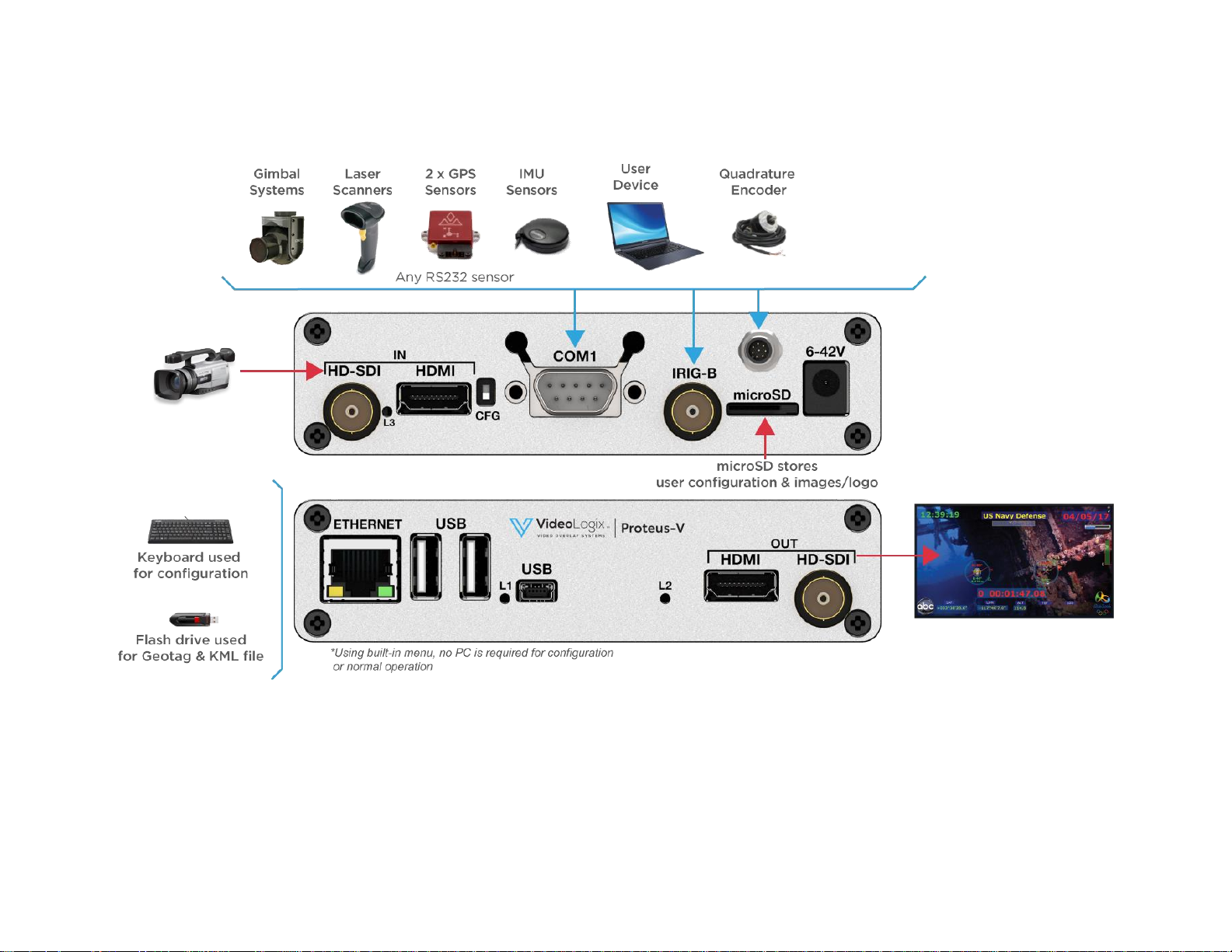
TYPICAL INTERCONNECT DIAGRAM
Diagram below illustrates a few the possible applications.
Page 6
6
GLOSSARY TERMS
Term
Definition
SCS
Software Communication Specification
CSV
Comma Separated Values
TB
Terminal Block
UM
User Manual
GPS
Global Position System
COMMUNICATION
COM PORTS
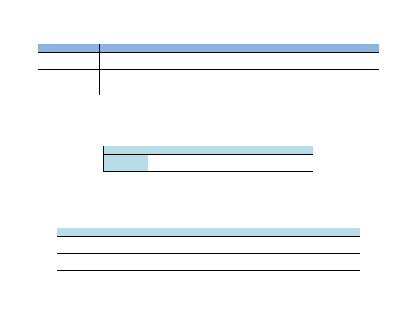
PROTEUS provides 2 x serial ports (COM1 & COM2) for communication with the external devices:
COM PORT
Location
Pin assignments
COM1
RS232:
Rear Panel DB9
2=RX, 3=TX, 5=GND
COM2
RS232:
Internal J54 & J16
J54:
1=RX, 2=GND, 3=TX
COM PORTS: BAUD RATES
• COM ports are fixed for N, 8, 1. However, baud rates can be set to 4800, 9600, 19200, 38400, 57600 or 115200.
COM PORTS: DEVICE TYPES
COM ports can be interfaced to various sensors. Table below shows the current list and their corresponding Device Type setting.
Attach Sensor/Device
Corresponding Device Type setting
Any device transmitting CSV sentences i.e. laptop, sensors
CSV1, CSV2, CSV3, CSV4 (See CSV formats for more detail)
All NMEA-0183 compatible devices i.e. GPS Modem, Sounder, etc.
CSV1, CSV2, CSV3, CSV4
PROTEUS App
CSV1
PuTTY or similar program
CSV1
Vector NAV IMU
VectorNav
General Dynamic CINEFLEX
CINEFLEX
Page 7
7
COM PORTS: CONFIGURATION
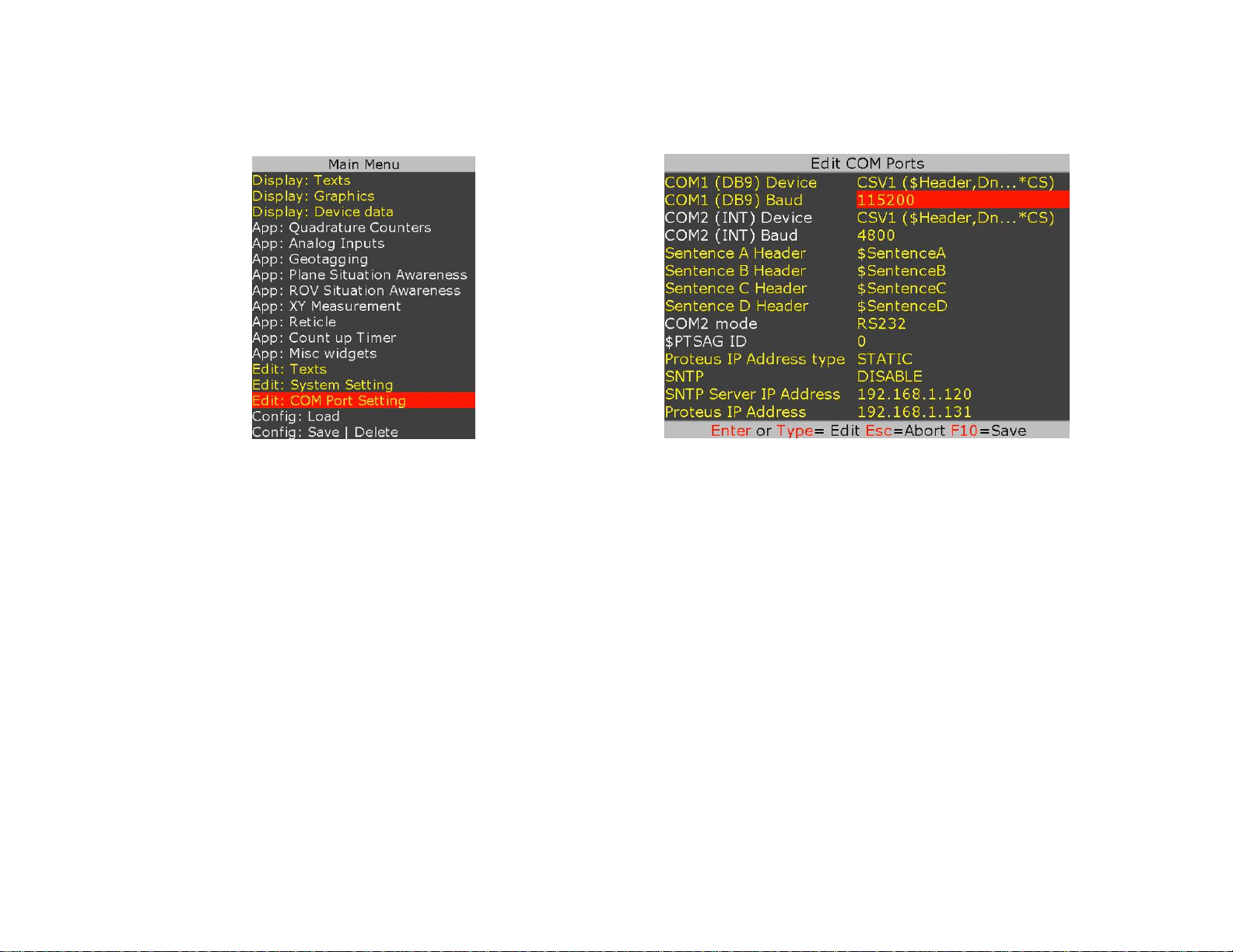
Press F9 to display the Main Menu. Follow Figure 1-Figure 2 to configure COM ports for desire baud rate & device.
Figure 1
Figure 2
COM1
COM1 (DB9) is configured as DTE (PC) i.e. RX=Pin2, TX=Pin3. Thus, sensors such as GPS can be directly connected to the DB9 without the need for NULL
modem cable. However, a NULL modem cable is required to interface PROTEUS to a PC.
This port can be used to send remote commands defined in SCS (Software Communication Specification) or connect any RS232 sensor.
COM2
COM2 is located internal. Signals TX & RX are provided at J16 connector (Compatible with Garmin GPS 18x LVC) as well as Terminal Block J54.
This port can be used to send remote commands defined in SCS (Software Communication Specification) or connect any RS232 sensor.
USB DEVICE PORT
This port is used to upgrade the internal firmware. When connected to a PC, it will enumerate as a COM port. This port can also be used to send remote
commands defined in SCS (Software Communication Specification).
USB HOST PORTS
PROTEUS has 2 USB host ports. Typical devices connected to these ports are USB keyboard and USB Flash drive.
Page 8

8
CSV FORMATS
A CSV (Comma Separated Values) is an ASCII sentence composed of a unique header, followed by up to 12 comma separated values and a checksum.
$Header,VAL1,VAL2,VAL3,VAL4,VAL5,VAL6,VAL7,VAL8,VAL9,VAL10,VAL11,VAL12*CS
$
Signifies start of the sentence.
Header
Sentence header. Follow Figure 1-2 to define your unique sentence header.
VALn
Each sentence contains multiple values (VALn) delimited by commas.
*
The asterisk serves as checksum delimiter.
CS
The checksum field contains two ASCII characters which indicate the hexadecimal value of the checksum.
PROTEUS supports 4 different CSV sentences:
Type
Sentence includes
Sentence Structure
Example
CSV1
$Header, Values…, Checksum
$HEADER,VAL1,VAL2,VAL3,...VALn*CS
$STEVE,45,315,200,100*XX
CSV2
$Header, Values…
$HEADER,VAL2,VAL3,...
$BRIAN,45,315,200,100
CSV3
$Values...
$VAL1,VAL2,VAL3,...
$45,315,200,100
CSV4
Values …
VAL1,VAL2,VAL3,..
45,315,200,100
Upon reception of a CSV sentence and confirmation of the sentence header (only CSV1), PROTEUS parses the sentence. Parsed values (VAL1 ... VAL12)
are sequentially stored in Registers # 40 through 87. Any widgets linked to these registers will automatically get updated. CSV sentence vary in length,
but each VALn is limited to 40 characters or less.
For more detail on how to use CSV sentences, see Display values from any csv sentence
The checksum field is the last field in a sentence and follows the checksum delimiter character “*”. The checksum is the 8-bit exclusive OR of all characters
in the sentence, including “,” delimiters, between but not including the “$” and the “*” delimiters. The hexadecimal values of the most significant and least
significant 4 bits of the result is converted to two ASCII characters (0-9, A-F (upper case)) for transmission. The most significant character is transmitted
first. Example: $GPGLL,5057.970,N,00146.110,E,142451,A*27<CR><LF>
In C checksum computation would be written as:
char sentence [] = “GPGLL,5057.970,N,00146.110,E,142451,A”;
int i;
char checksum = 0;
for ( i = 0; i < strlen(sentence); i++)
checksum ^= sentence[i];
Although not recommended, for CSV1 type sentences, checksum computation can be bypassed by replacing CS with XX.
Page 9
9
ETHERNET PORT
This port can be used to send remote commands defined in SCS (Software Communication Specification).
• 10M/100M auto sensing network interface
• Networking: Static or DHCP IPv4 addressing
• Subnet Mask: 255.255.255.0
• Default Gateway: 0.0.0.0
• UDP protocol. Port 9999
Follow Figure 1-Figure 2 to configure network interface. Following any change to the DHCP setting, power must be recycled for the change to take
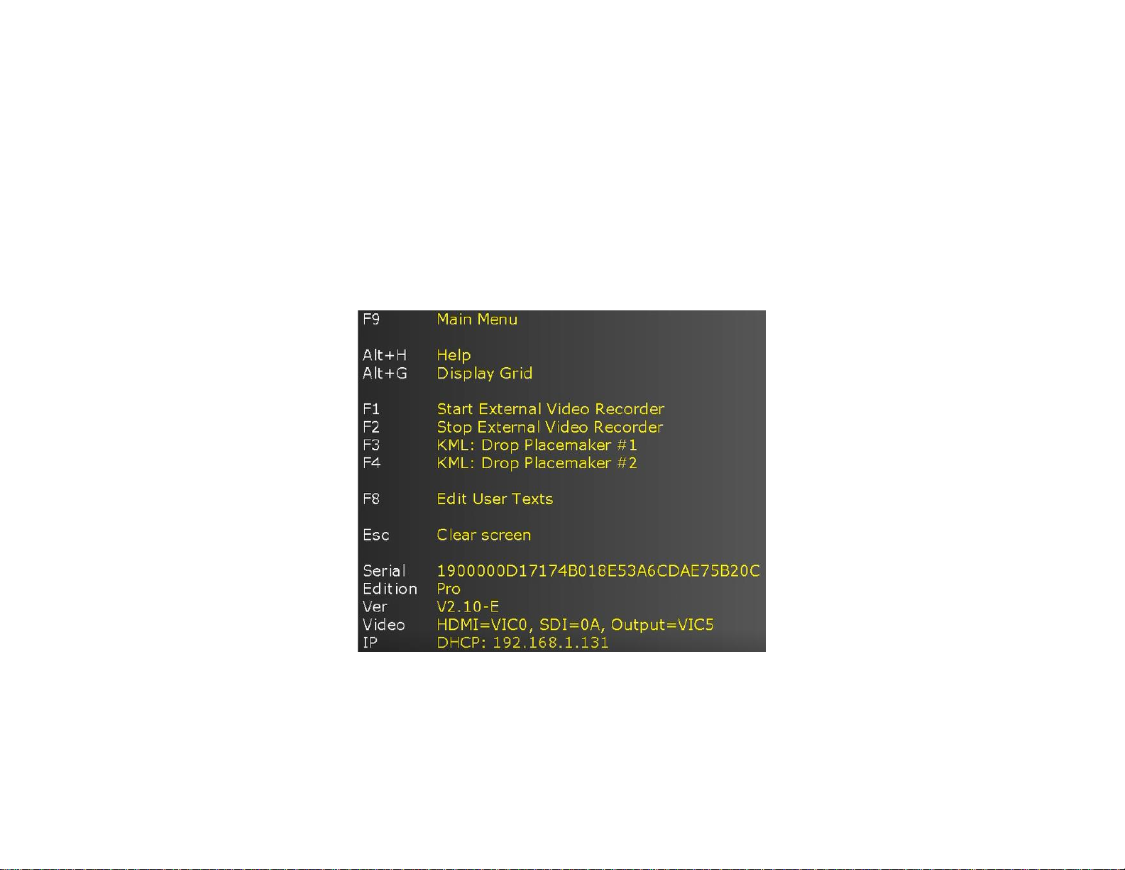
effect. PROTEUS’s IP address can be viewed by pressing Alt-h.
Page 10

10
VIDEO INPUT & OUTPUT
PROTEUS provides the following video input & output:
• SDI (HD & SD)
• HDMI (HD & SD)
PROTEUS does not support HDMI video with HDCP. It can only process one video input at a given time. If more than one input is connected at the same
time, PROTEUS selects a video input based on the following priorities:
1. HD-SDI
2. HDMI
PROTEUS does not scale video and the output resolution follows the input. PROTEUS provides simultaneous video outputs.
Page 11

11
VIDEO FRAME RATES
PROTEUS is compatible with the following video formats:
1080i @
50 / 60 Hz
1080p @
23.98 / 24 / 25/ 29.97/ 30 Hz
1080PsF @
23.98 / 24 Hz
720p @
50 / 59.94 / 60 Hz
NTSC 480i @
60 Hz
PAL 576i @
50 Hz
VIDEO DELAY
All OSD functions are superimposed into the video "on-the-fly." As a result, there is no degradation in video quality and the delay from the video input
to the video output is < 290 nsec.
IRIG INPUT
This interface can be used to input an external unmodulated IRIG-B signal. PROTEUS can decode IRIG-B time & date code. This interface can also be
used to input a composite video NTSC (M, J, 4.43) or PAL (B,D,G,H,I,M,N,CN) for purpose of superimposing it on a HD video as PIP.
Page 12
12
COMPOSITE INPUT (PIP)
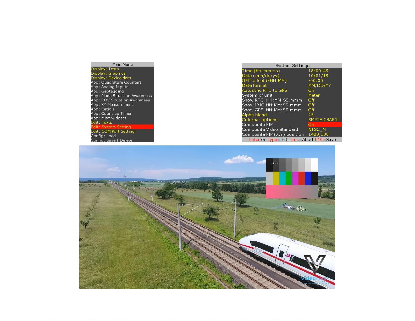
IRIG input can also be used to input a composite video NTSC (M, J, 4.43) or PAL (B,D,G,H,I,M,N,CN) for purpose of superimposing it on a HD video.
To enable PIP follow the pictures below. Composite video (as shown below as colorbar) can be superimposed anywhere on the 1920 x 1080.
Page 13
13
LOAD CONFIGURATION
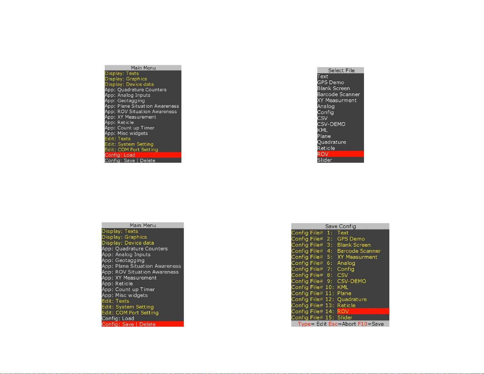
PROTEUS can maintain 16 different configurations. Follow figures below to load a configuration.
STORE CONFIGURATION
PROTEUS stores 16 different configurations. Follow figures below to save your configuration.
To save, type in the new file name in an empty field or highlight a file name (overwrite) and press F10 to save.
To delete, highlight the file name and press Ctrl + Alt + F10.
Page 14
14
TEXT, LOGO AND DATA INSERTER
QUICK TUTORIAL
DISPLAY TIME, DATE
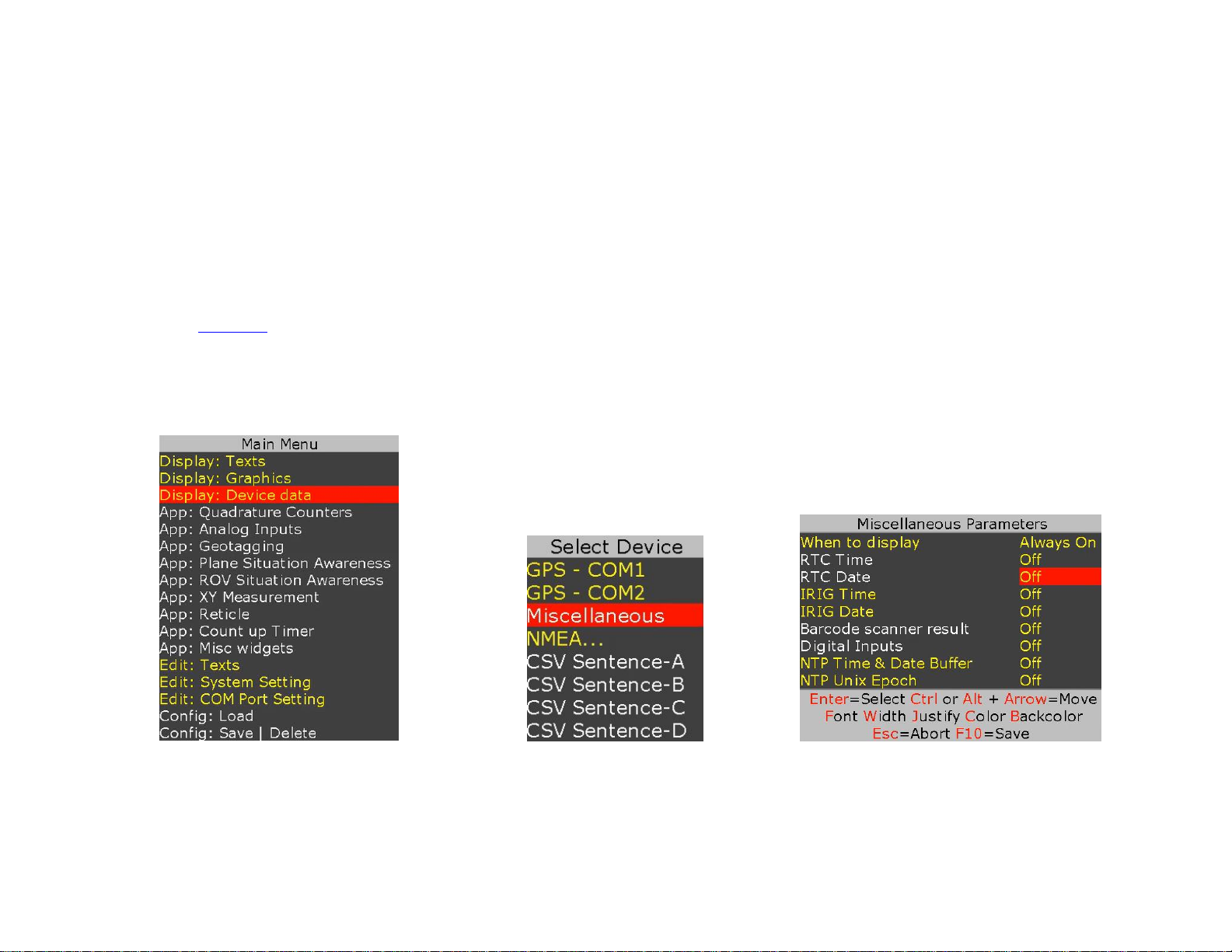
1. Press F9 to display main menu
2. Follow Figure 3 - Figure 5 to insert the desired parameter
3. On Figure 5, use ↕ arrow keys to select “RTC Time”
4. Press “Enter” to select “YES”
5. RTC time will appear on the screen and flashing.
6. Use shortcuts keys to change the field attributes as described below:
“Font select, field Width, text Justification, text Color, text Background and Ctrl or Alt + ↕↔ text position”
7. Repeat steps 3 through 6 to display “RTC Date”
8. Press F10 to save and exit.
Figure 3
Figure 4
Figure 5
Page 15
15
DISPLAY TEXT
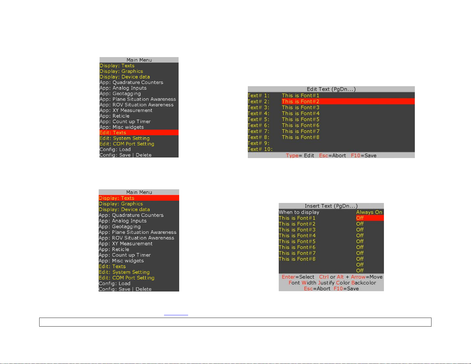
Press F9 to display Main Menu. Follow Figure 6 - Figure 7 to type-in or edit pre-exiting texts.
Figure 6
Figure 7
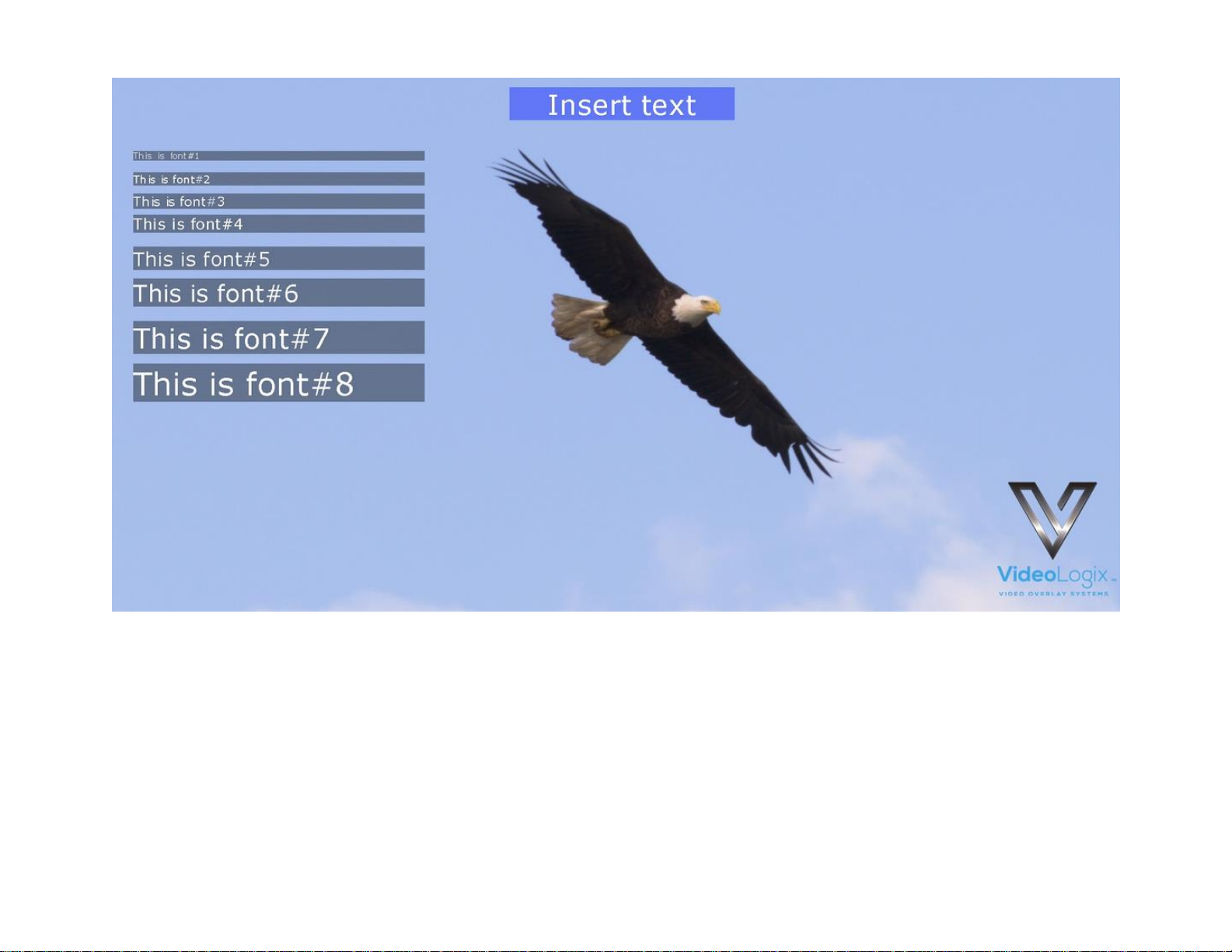
Follow Figure 8 - Figure 9 to display text on video.
Figure 8
Figure 9
While in Figure 9, select the desire text and use shortcuts keys to format the text as described below:
Font select, field Width, text Justification, text Color, text Background and Ctrl or Alt + ↕↔ text position
Page 16
16
Page 17
17
DISPLAY IMAGES
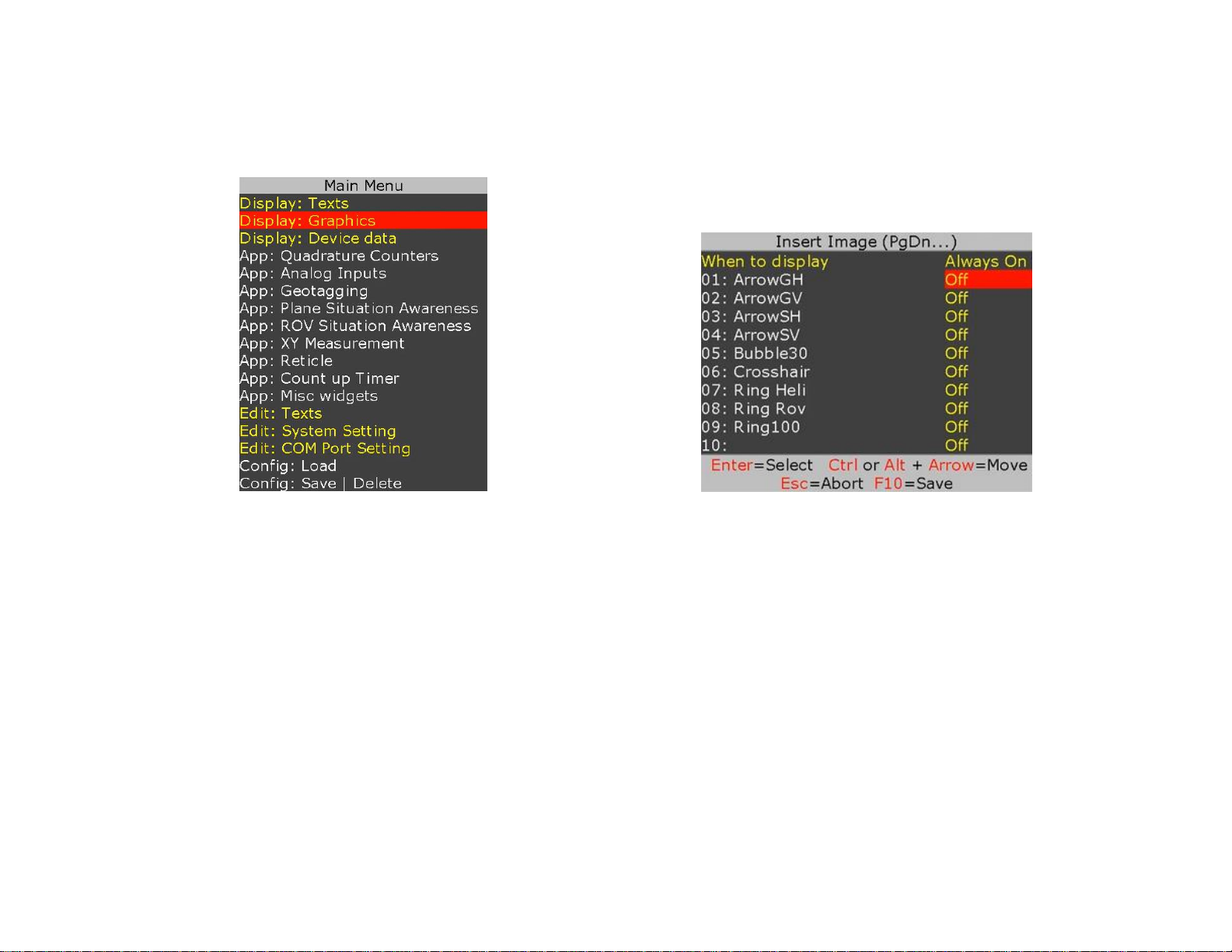
Please review Appendix D – images on how to prepare images for use with PROTEUS.
Press F9 to display Main Menu. Follow Figure 10 - Figure 11 to display images.
Figure 10
Figure 11
While in Figure 11, use ↕ to select a desire image and use Ctrl or Alt + ↕↔ to position the image on screen.
Page 18
18
DISPLAY GPS DATA
• Two independent GPS modems can be connected to COM1 & COM2 at the same time.
• COM ports are fixed for N, 8, 1. Follow Figure 1 - Figure 2 to configure for desire baud rate
• $GPRMC, $GPGGA, $PTSAG, $GPWPL, $GPGSA, $GPGSV, $GPGGL….
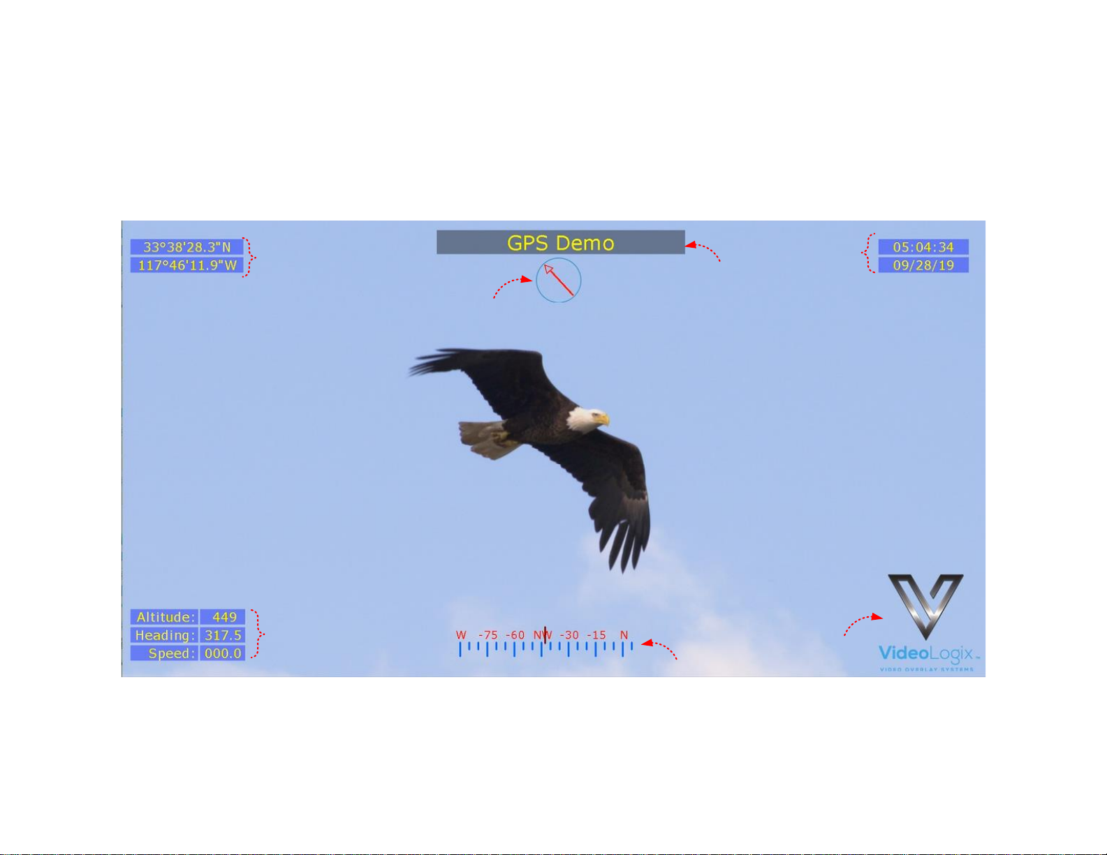
A sample GPS file is provided with your PROTEUS. To load it, press F9, go to “Config: Load” and select “GPS”.
1
1
2
1
3
4
4
1
GPS data
Obtained directly from GPS modem
2
Circular Compass
Controlled via GPS heading
3
Rolling Compass
Controlled via GPS heading
4
Misc. Parameters
Title, Logo. Fully configurable by the user
Page 19
19
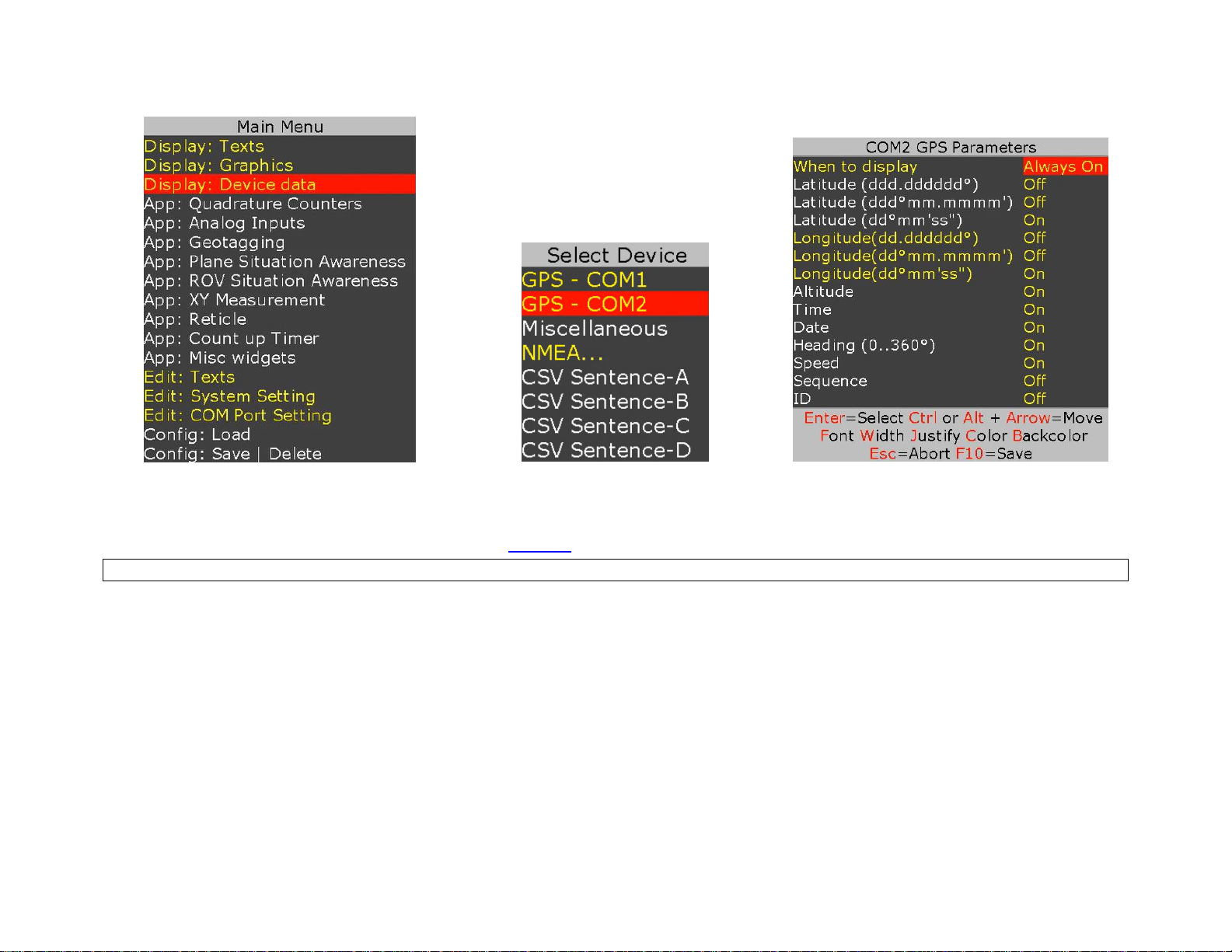
To customize the sample file to meet your needs, follow Figure 12 - Figure 14.
Figure 12
Figure 13
Figure 14
While in Figure 14 select the desire GPS parameter and use shortcuts keys to format the text as described below:
Font select, field Width, text Justification, text Color, text Background and Ctrl or Alt + ↕↔ text position
Page 20
20
DISPLAY NMEA DATA
• PROTEUS intrinsically supports many NMEA sentences such as $GPRMC, $GPGGA, $PTSAG, $GPWPL, $GPGSA, $GPGSV,
$GPGGL, $SDDPT, $SDDBT, $WIMTW, $WIMWV, $VNINS, $VNIMU, $VNYPR, $PTNTHPR, $HCHDG, $HCHDT, etc.
• For above messages, just configure COM port and PROTEUS is ready to receive messages & manage your visual data
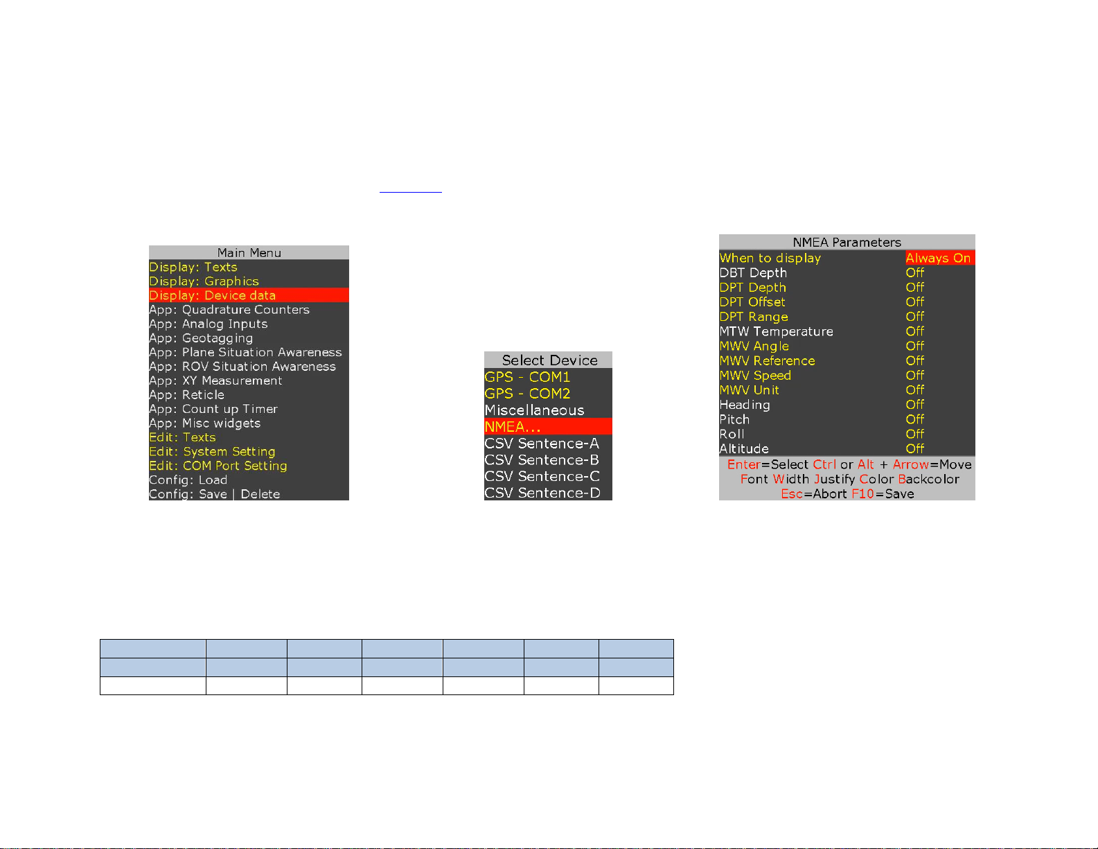
• Follow Figure 15-Figure 17 and Figure 12 - Figure 14 to display NMEA parameters.
Figure 15
Figure 16
Figure 17
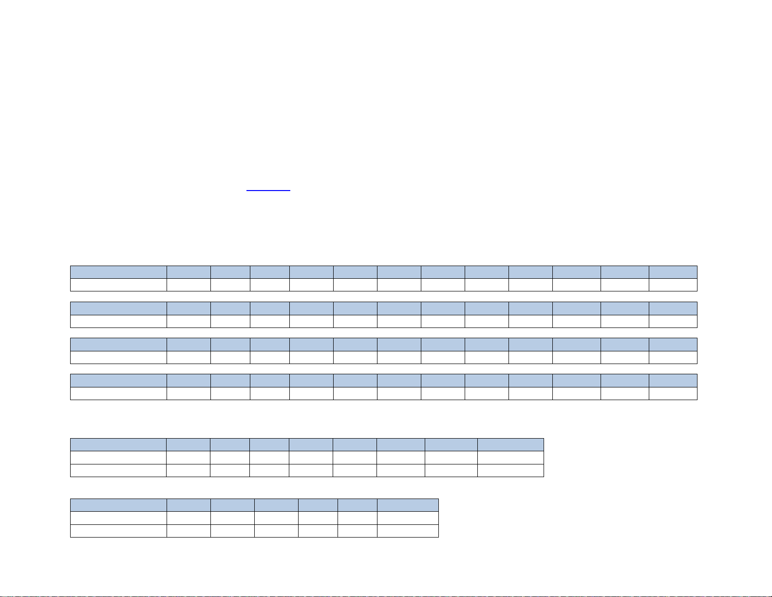
You may come across a NMEA sentence that is not intrinsically supported by PROTEUS for example $PTCF. To configure PROTEUS to receive this
sentence, follow Figure 1 - Figure 2 and replace $SentenceA with $PTCF. Upon reception of $PTCF sentence, PROTEUS parses the sentence and parsed
values (VAL1..VAL6) are sequentially stored in Registers # 40-45 as shown below:
$PTCF,HHH.H,T,+RRR.R,+PPP.P,+rrr.rr,+ppp.pp*CS
$PTCF
VAL1
VAL2
VAL3
VAL4
VAL5
VAL6
Register
40
41
42
43
44
45
Values
HHH.H
T
+RRR.R
+PPP.PP
+rrr.rr
+ppp.pp
For more detail on how to display each value, please see Display values from any csv sentence
Page 21
21
DISPLAY VALUES FROM ANY CSV SENTENCE
DISPLAY VALUES FROM ANY UNSUPPORTED NMEA SENTENCE
A CSV (Comma Separated Values) is an ASCII sentence composed of a unique header, followed by up to 12 comma separated values and a checksum.
$Header,VAL1,VAL2,VAL3,VAL4,VAL5,VAL6,VAL7,VAL8,VAL9,VAL10,VAL11,VAL12*XX
• All NMEA-0183 messages are CSV
• PROTEUS intrinsically supports many of the NMEA-0183 messages i.e. $GPRMC, $GPGGA, $PTSAG, $GPWPL, $GPGSA, $GPGSV,
$GPGGL, $SDDPT, $SDDBT, $WIMTW, $WIMWV, $VNINS, $VNIMU, $VNYPR, $PTNTHPR, $HCHDG, $HCHDT, etc.
• For these messages, just configure COM port and PROTEUS is ready to receive messages & manage your visual data
• There may be instances where you want to send your own CSV message or support a new NMEA message
• You can configure PROTEUS to receive up to 4 customize CSV messages (A, B, C, D)
• Upon reception of CSV sentence, PROTEUS verifies checksum & parses the message
• For each message, parsed values (VAL1.. VAL12) are stored in Registers # 40-87 as shown below:
$Header-A
VAL1
VAL2
VAL3
VAL4
VAL5
VAL6
VAL7
VAL8
VAL9
VAL10
VAL11
VAL12
Register
40
41
42
43
44
45
46
47
48
49
50
51
$Header-B
VAL1
VAL2
VAL3
VAL4
VAL5
VAL6
VAL7
VAL8
VAL9
VAL10
VAL11
VAL12
Register
52
53
54
55
56
57
58
59
60
61
62
63
$Header-C
VAL1
VAL2
VAL3
VAL4
VAL5
VAL6
VAL7
VAL8
VAL9
VAL10
VAL11
VAL12
Register
64
65
66
67
68
69
70
71
72
73
74
75
$Header-D
VAL1
VAL2
VAL3
VAL4
VAL5
VAL6
VAL7
VAL8
VAL9
VAL10
VAL11
VAL12
Register
76
77
78
79
80
81
82
83
84
85
86
87
EXAMPLE
$Header-A,1,22,333,4444,55555,666666,7777777,88888888*XX
$Header-A
VAL1
VAL2
VAL3
VAL4
VAL5
VAL6
VAL7
VAL8
Register
40
41
42
43
44
45
46
47
Values
1
22
333
4444
55555
666666
7777777
88888888
$Header-C,This,is,an,,,Example*XX
$Header-C
VAL1
VAL2
VAL3
VAL4
VAL5
VAL6
Register
64
65
66
67
Values
This
is
an
Example
Page 22
22
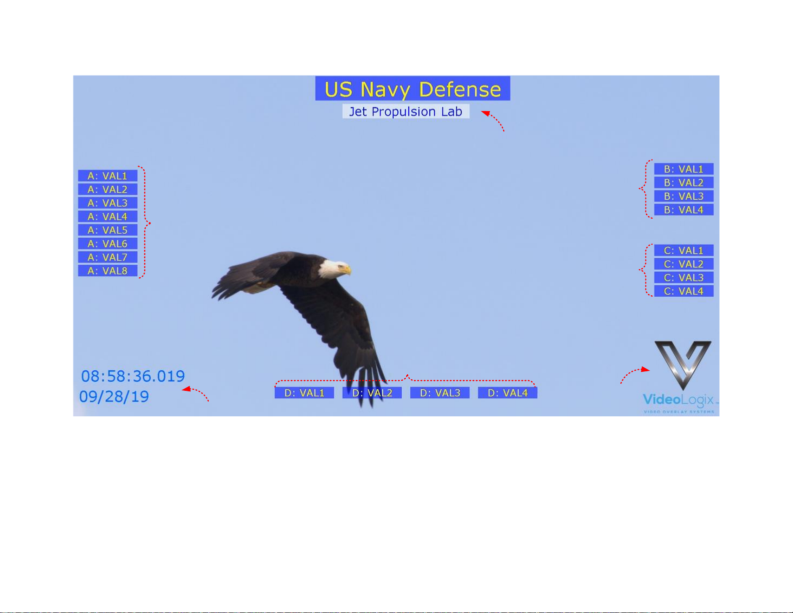
A sample CSV file is provided with your PROTEUS. To load it, press F9, go to “Config: Load” and select “CSV”.
1
5
5
5
4
2
3
1
Sentence-A values
VAL1..VAL8
2
Sentence-B values
VAL1..VAL4
3
Sentence-C values
VAL1..VAL4
4
Sentence-D values
VAL1..VAL4
5
Misc. Parameters
Texts, RTC Time & Date, Logo. Fully configurable by the user
Page 23
23
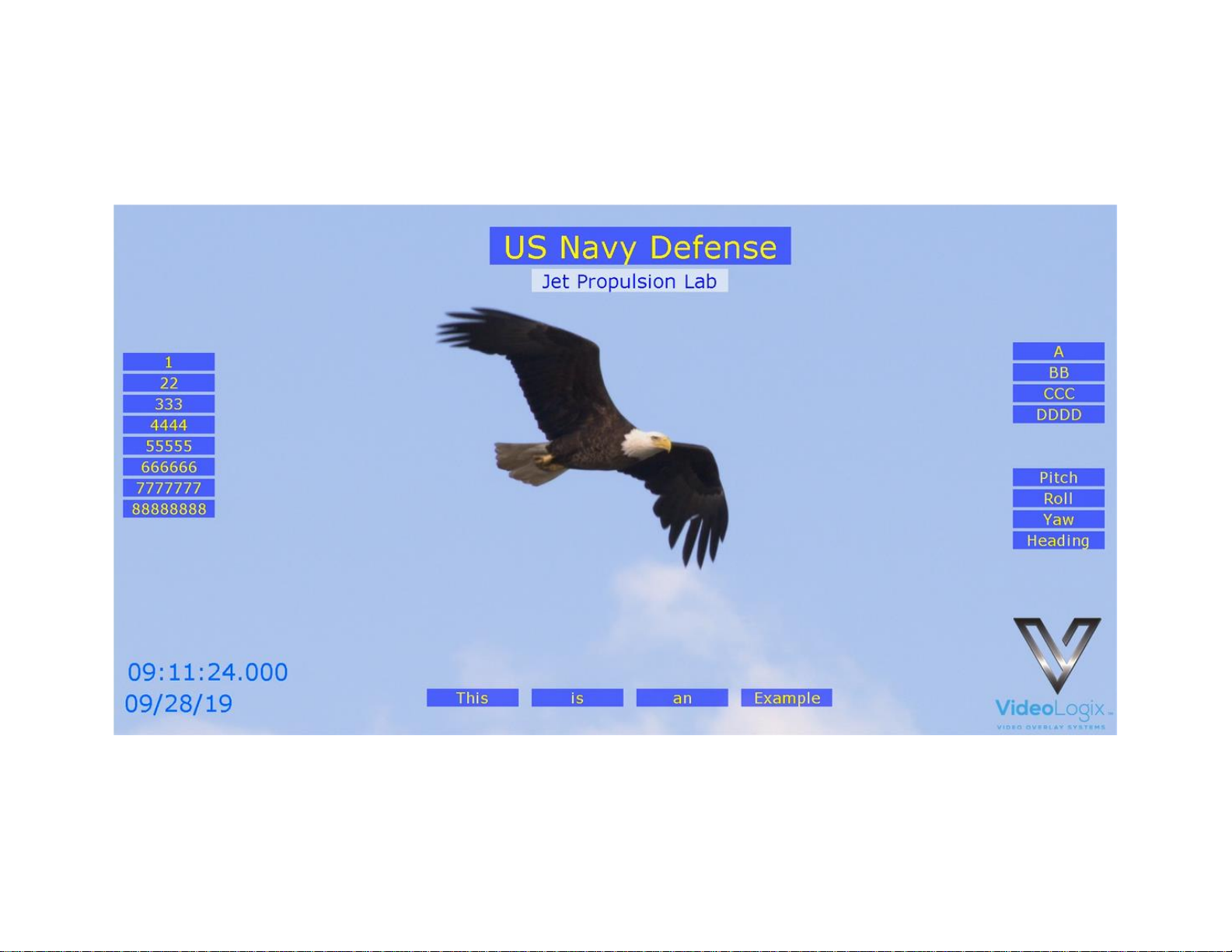
Upon transmission of the following sentences (use PuTTY @115K, N,8 ,1), their values should appear as shown in Figure 18.
$SentenceA,1,22,333,4444,55555,666666,7777777,88888888*XX
$SentenceB,A,BB,CCC,DDDD*XX
$SentenceC,Pitch,Roll,Yaw,Heading*XX
$SentenceD,This,is,an,Example*XX
Figure 18
Any individual value can also be updated by sending command $VL43. For example:
• To change VAL7 from SentenceA to 777 send: $VL43,46,777*XX.
• To change VAL6, VAL7, VAL8 from SentenceA to 777,8888,99999 accordingly, send: $VL43,45,777,8888,99999*XX.
Page 24
24
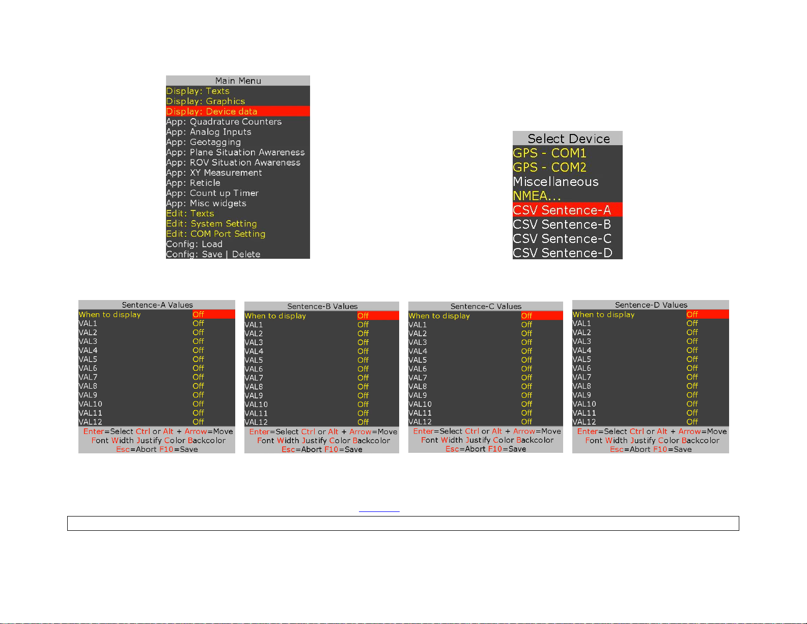
To customize the sample file to meet your needs, follow Figure 19-Figure 24.
Figure 19
Figure 20
Figure 21
Figure 22
Figure 23
Figure 24
Figure 25
While in Figure 21- Figure 24 , select the desire CSV value and use shortcuts keys to format the text as described below:
Font select, field Width, text Justification, text Color, text Background and Ctrl or Alt + ↕↔ text position.
Page 25
25
APPEND MILLISECOND COUNTER TO IRIG, GPS, RTC TIME
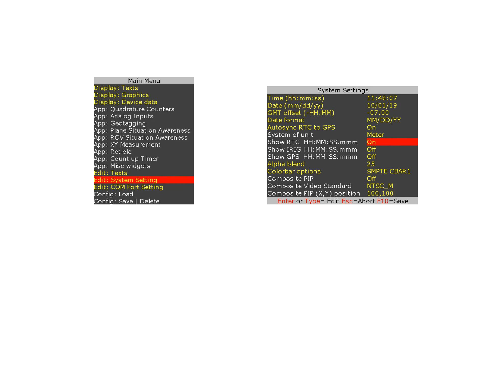
Follow Figure 26 - Figure 27 to append millisecond count to RTC, IRIB and GPS time. Millisecond counter is reset on second rollover.
Once enable, the displayed time will refresh at video frame rate i.e. 30 time per second for 1080p@30
Figure 26
Figure 27
Page 26
26
SNTP
SNTP (Simple Network Time Protocol) synchronizes PROTEUS built-in RTC with a server that has already been synchronized by a source such as a
radio, satellite receiver or modem.
PROTEUS SNTP Client operates in unicast to obtain time over the network. It polls its SNTP Server on regular interval and waits to receive a reply from
that Server. When one is received, it verifies that the reply contains a valid update by applying a set of ‘sanity check’ recommended by RFC 4330. It
then applies Server clock directly to its local clock (RTC).
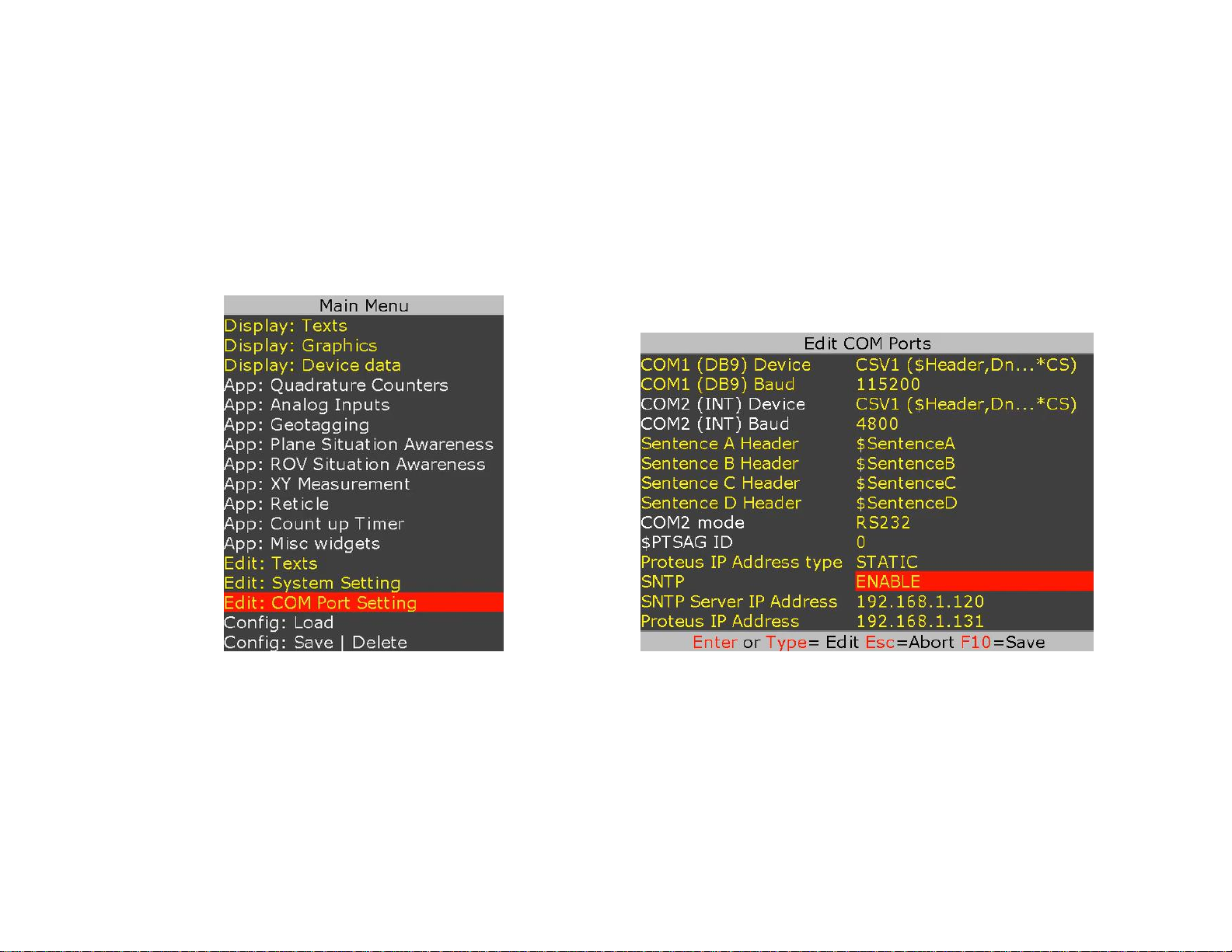
Follow Figure 28 - Figure 29 to configure SNTP.
Figure 28
Figure 29
Page 27
27
APPS
QUADRATURE OR SIMPLE COUNTERS
• Two Quadrature counters.
• Counters are 26-bits wide. Maximum count 67,108,863 or ±33,554,431
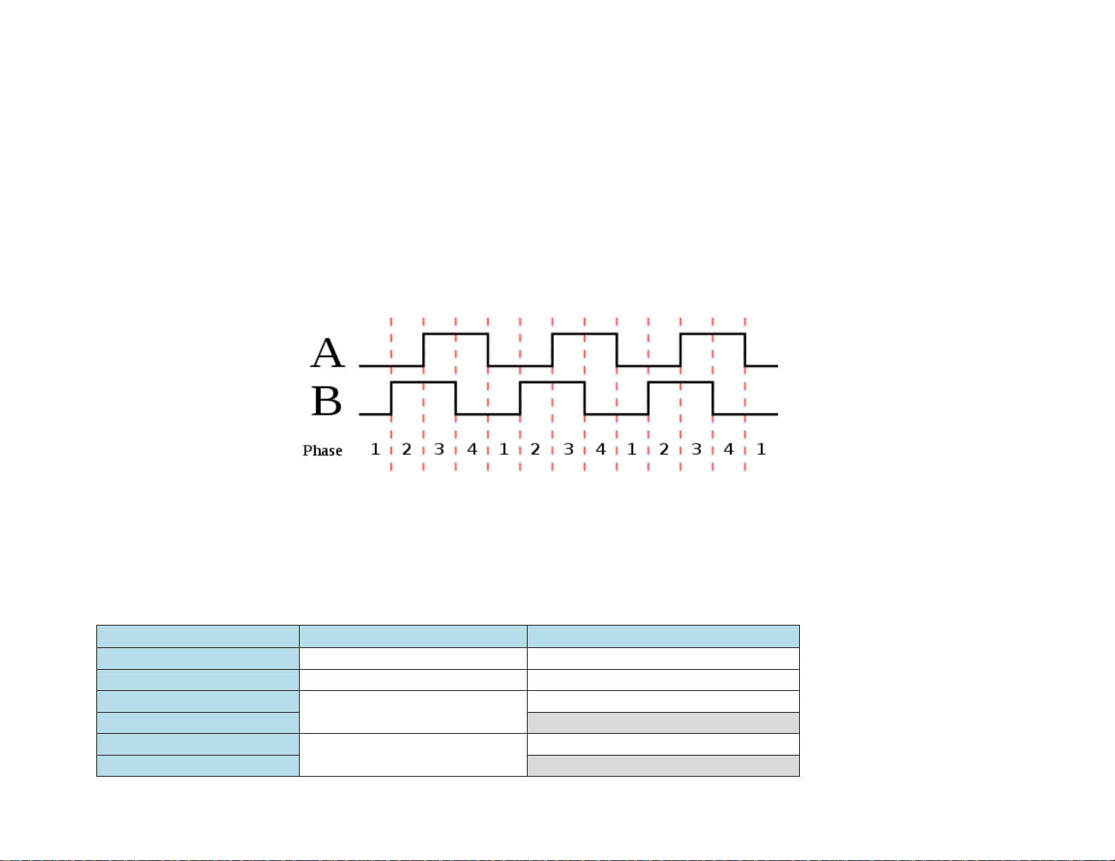
• Configurable line resolution 𝑥1, 𝑥2, 𝑥4. See diagram below for additional detail
• Dedicated RESET pins
• Raw counter value can be converted to any unit (distance, speed, etc.) using
𝑚𝑎𝑝𝑝𝑒𝑑_𝑐𝑜𝑢𝑛𝑡 = 𝑚 ∗ 𝑟𝑎𝑤_𝑐𝑜𝑢𝑛𝑡 + 𝑏
• Counter values can be used to control “XY Measurement app” or “Reticle app”
X1: 1 1 1 1 2 2 2 2 3 3 3 3 4
X2: 1 1 2 2 3 3 4 4 5 5 6 6 7
X4: 1 2 3 4 5 6 7 8 9 10 11 12 13
The counters can be configured as Quadrature or Simple counters.
Terminal Block (J52-J53) Pins
As Quadrature Counters
As Simple Counters
DIN1
RESET for Counter 1
RESET for Counter 1
DIN2
RESET for Counter 2
RESET for Counter 2
DIN3
Quadrature Counter 1 inputs
Simple Counter 1 input
DIN4
-
DIN5
Quadrature Counter 2 inputs
Simple Counter 2 input
DIN6
-
Page 28
28
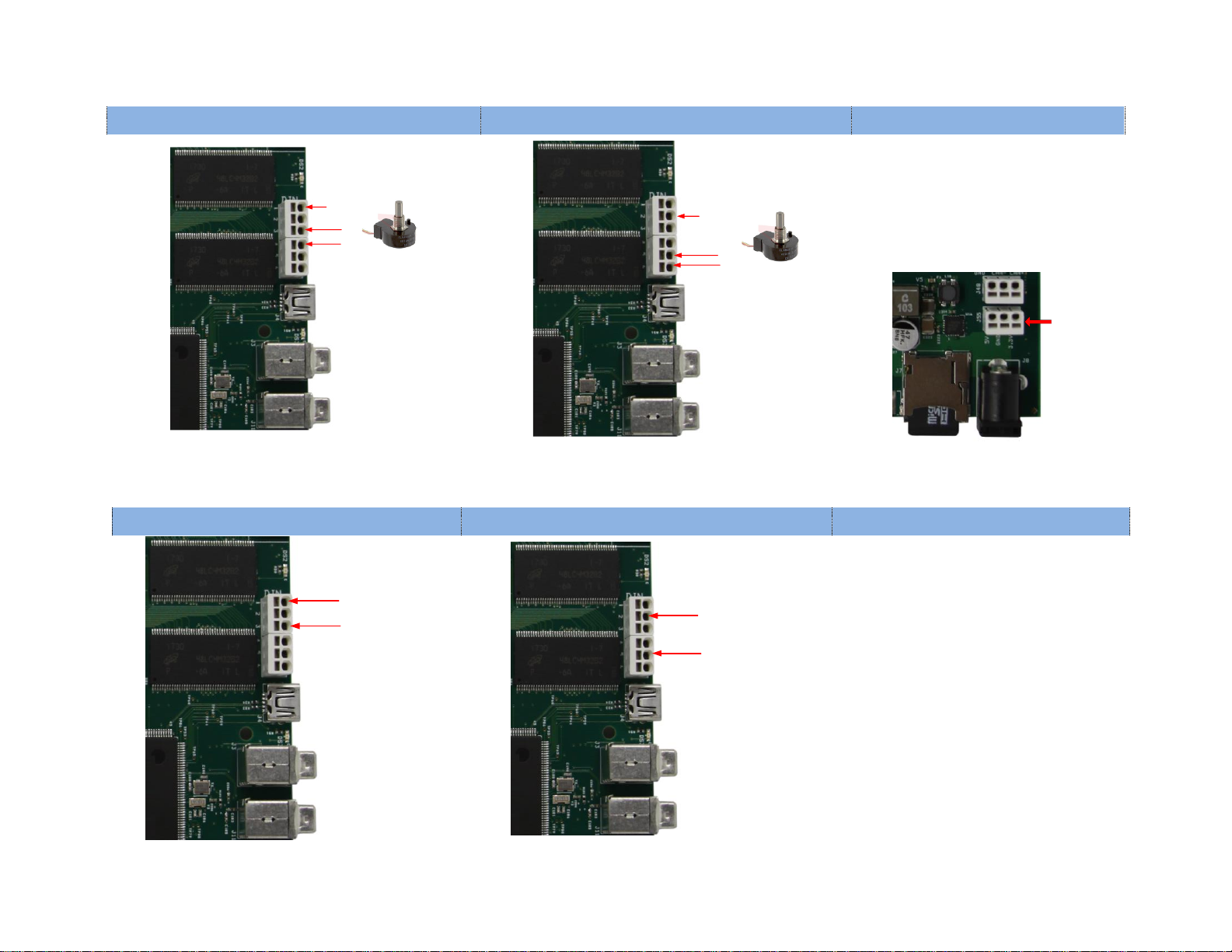
Typical wiring connection for Quadrature Counters
Quadrature Counter 1
Quadrature Counter 2
Electrical Interface
A1
B1
RESET1
A2
B2
RESET2
Input compatibilty:
• 0-5V logic (10ma sink current)
• Frequency < 10MHz
Power & ground can be provided to
the quadrature encoder via J55:
+5V
+3.3V
GND
Typical wiring connection for Simple Counters
Simple Counter 1
Simple Counter 2
Electrical Interface
Counter 1 pulse
RESET1
Counter 2 pulse
RESET2
Input compatibilty:
• 0-5V logic (10ma sink current)
• Frequency < 1KHz (5msec debouce)
Page 29
29
CONFIGURE COUNTERS
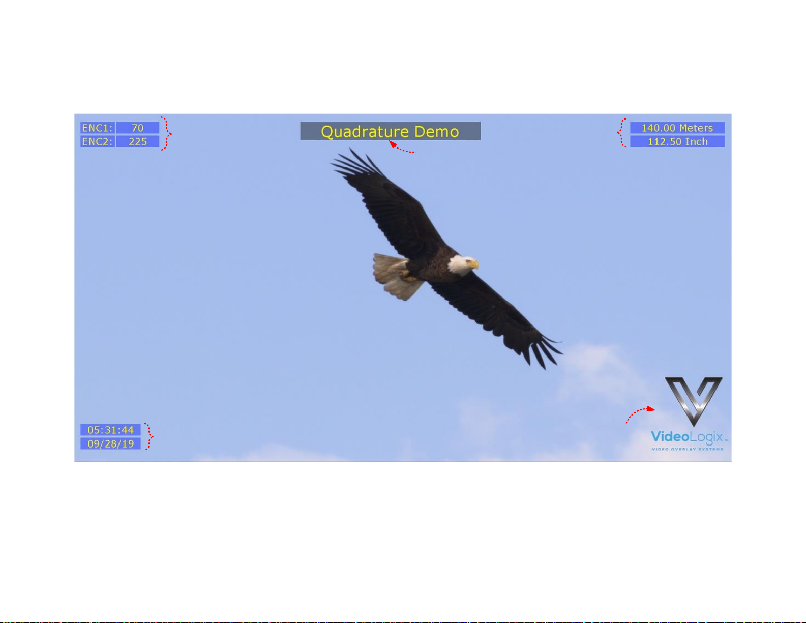
A sample Quadrature file is provided with your PROTEUS. To load it, press F9, go to “Config: Load” and select “Quadrature”.
1 2
3
3
3
1
Raw count
𝑟𝑎𝑤_𝑐𝑜𝑢𝑛𝑡 = 67,108,863 or ± 33,554,431
2
Mapped count
𝑚𝑎𝑝𝑝𝑒𝑑_𝑐𝑜𝑢𝑛𝑡 = 𝑚 ∗ 𝑟𝑎𝑤_𝑐𝑜𝑢𝑛𝑡 + 𝑏
3
Misc. Parameters
Title, Time & Date, Logo. Fully configurable by the user
Page 30
30
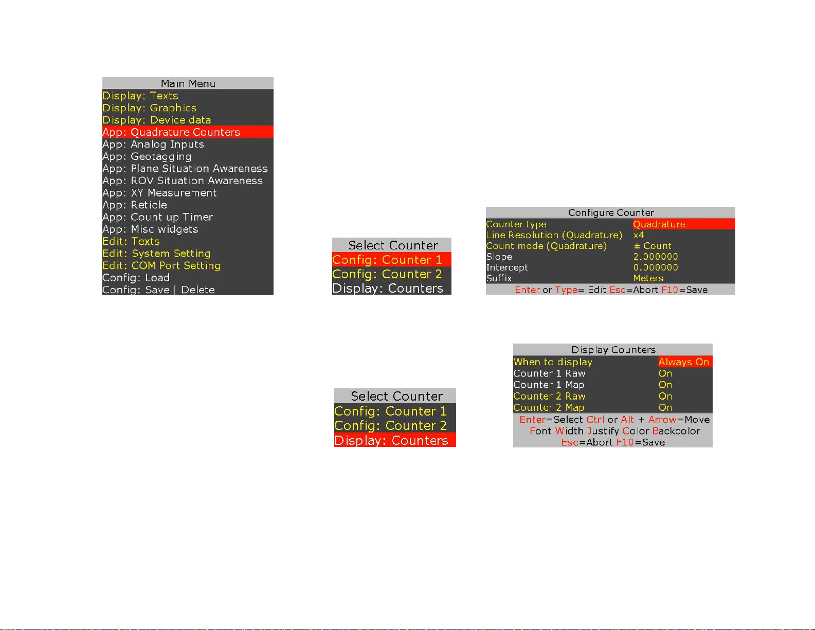
To customize the sample file to meet your needs, follow Figure 30 - Figure 32
Figure 30
Figure 31 Figure 32
Follow Figure 33 - Figure 34 to display map and raw counts.
Figure 33 Figure 34
EXAMPLE
Configure counter 1 for 0.0023 inch/count and display result.
• Follow Figure 30 - Figure 32 to set Counter 1 “Slope” and “Intercept” to 0.0023 and 0 respectively.
• Follow Figure 30, Figure 33 - Figure 34 to display “Counter 1 Map”
Page 31
31
ANALOG DATA
• Four Analog inputs
• Input range 0..3.3V
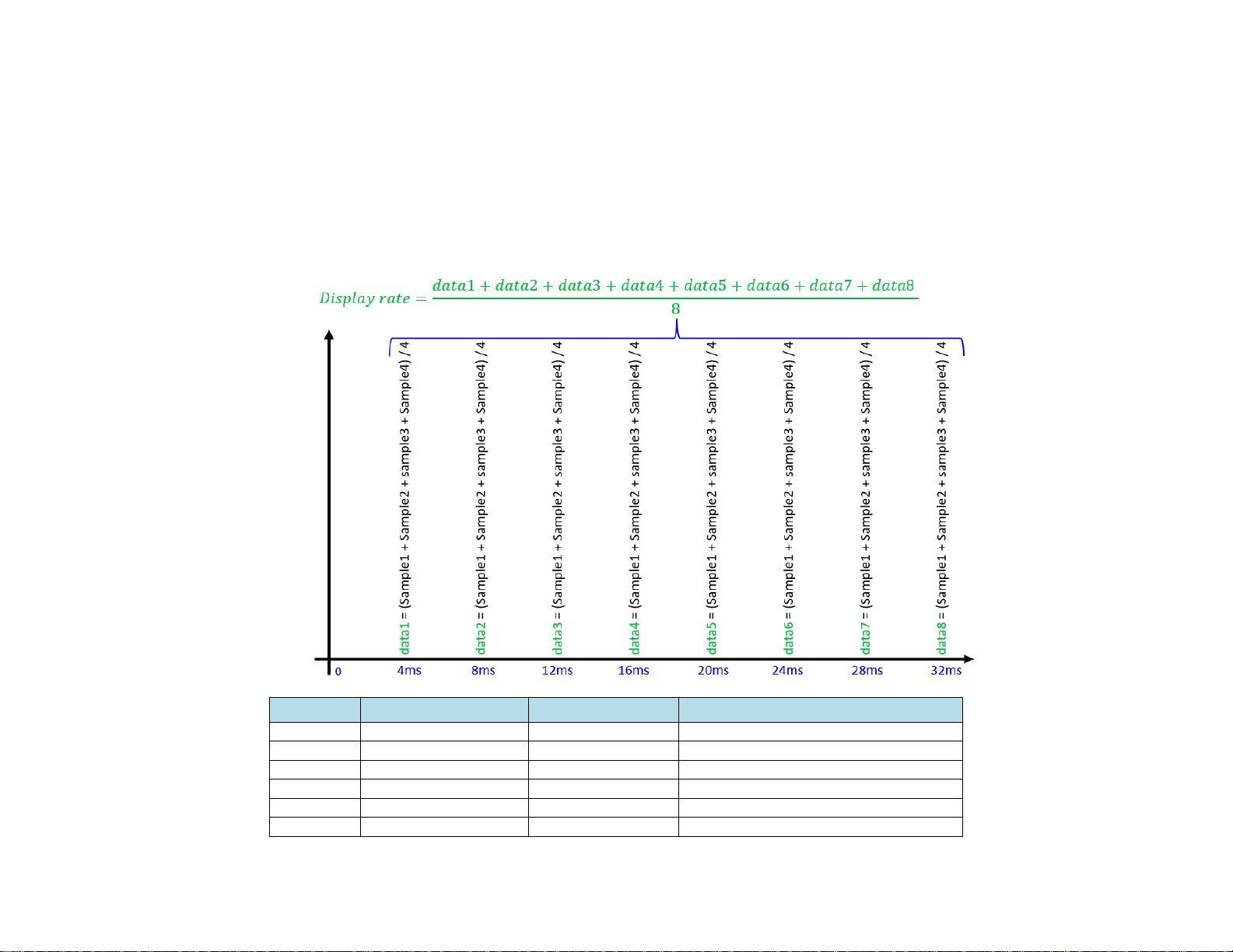
• 12-Bit ADC, 250 Hz sample rate, 31.25 Hz display rate. See diagram below for additional detail
• Internal low pass RC filter (24Ω, 5600pF)
• Analog signals can be converted to any unit using 𝑚𝑎𝑝𝑝𝑒𝑑_𝑣𝑎𝑙𝑢𝑒 = 𝑚 ∗ 𝑎𝑑𝑐_𝑣𝑎𝑙𝑢𝑒 + 𝑏
• Analog signals can also be used to control “XY Measurement app” or “Reticle app”
TB: J50
Description
Range
Corresponding 12-bit ADC Value
Pin 1
GND
-
-
Pin 2
Analog Input CH1
0..3.3V
0..4095
Pin 3
Analog Input CH2
0..3.3V
0..4095
Pin 4
Analog Input CH3
0..3.3V
0..4095
Pin 5
Analog Input CH4
0..3.3V
0..4095
Pin 6
GND
-
-
Page 32
32
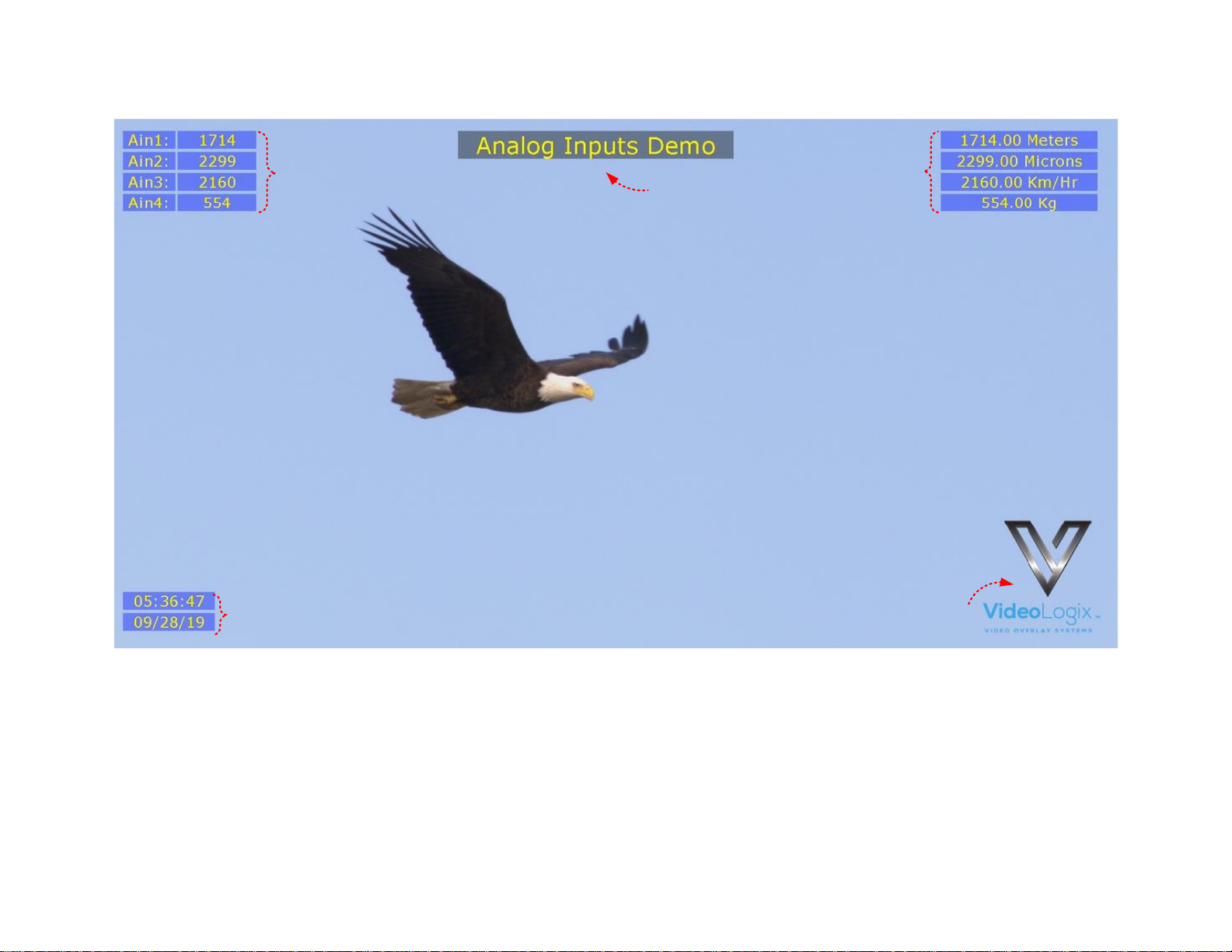
A sample Analog file is provided with your PROTEUS. To load it, press F9, go to “Config: Load” and select “Analog”.
1
2
3
3 3
1
Raw Analog values
𝑎𝑑𝑐_𝑣𝑎𝑙𝑢𝑒 = 0..4095
2
Mapped Analog values
𝑚𝑎𝑝𝑝𝑒𝑑_𝑣𝑎𝑙𝑢𝑒 = 𝑚 ∗ 𝑎𝑑𝑐_𝑣𝑎𝑙𝑢𝑒 + 𝑏
3
Misc. Parameters
Title, Time & Date, Logo. Fully configurable by the user
Page 33
33
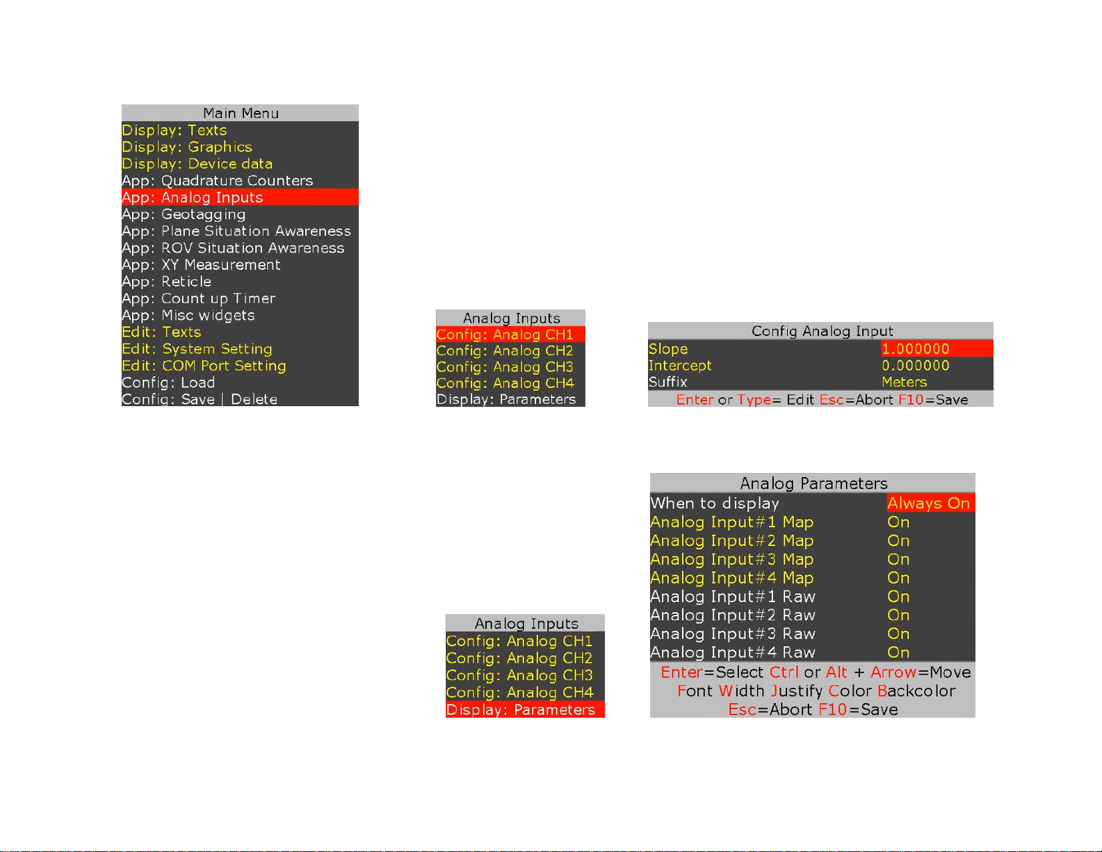
To customize the sample file to meet your needs, follow Figure 35 - Figure 37:
Figure 35
Figure 36 Figure 37
Follow Figure 38 - Figure 39 to display map and raw values.
Figure 38 Figure 39
Page 34
34
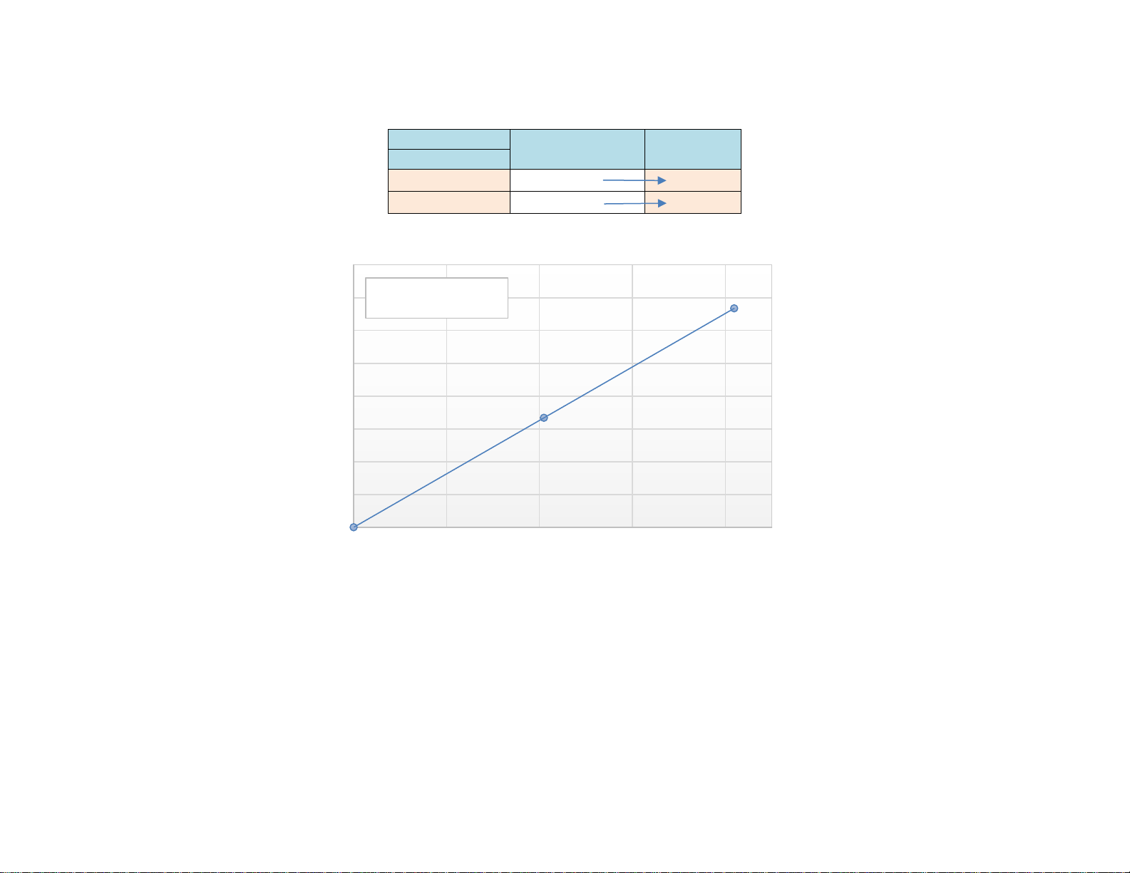
EXAMPLE 1
Configure analog channel 1 to convert 0-3.3V input to display 0 - 667.5 feet.
Input
ADC Count
Represent
(feet)
3.3V
0 0 0
3.3
4095
667.5
Follow Figure 35 - Figure 37 to set CH1 “Slope” & “Intercept” to 0.163 and 0.0272 respectively.
Follow Figure 38 - Figure 39 to display “Analog Input #1 Map”
To quickly get familiar with this app, please watch our short tutorial video “Tutorial Analog Inputs” on our web site.
y = 0.163x + 0.0272
0
100
200
300
400
500
600
700
800
0 1000 2000 3000 4000
Length
Slope = 0.163
Intercept = 0.0272
Page 35
35
XY MEASUREMENT
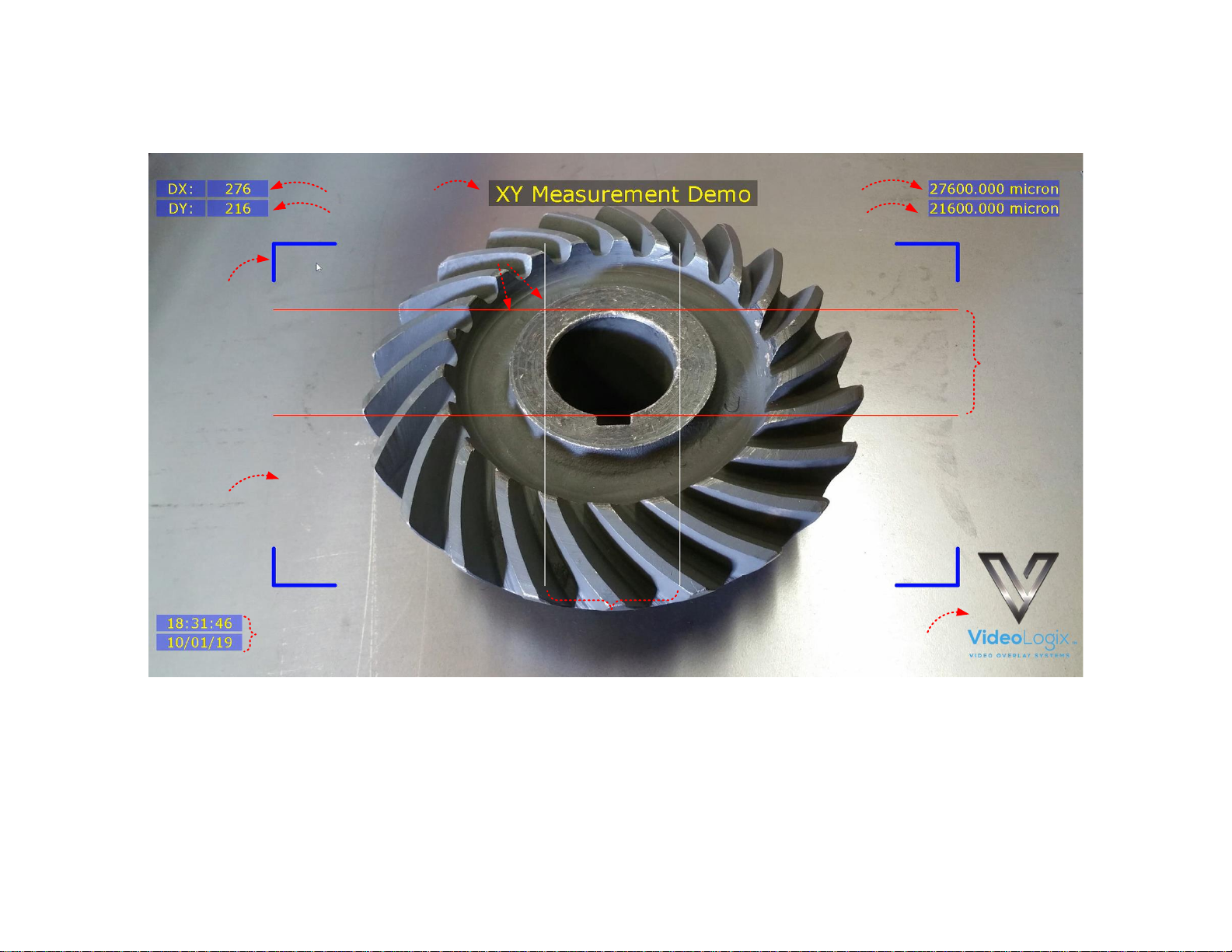
A sample XY measurement file is provided with your PROTEUS. To load it, press F9, go to “Config: Load” and select file “XY Measurement”
2A 2B
6
6
6
1
3A
3B
4
5
2A
3A
1
Markers
𝑥1, 𝑥2,𝑦1, 𝑦2 markers. Can be moved via Analog inputs, quadrature inputs, RS232 command, arrow keys
2A
Delta X
DX = |x2 – x1|
2B
Calibrated DX
𝐶𝑋 = 𝑚𝑥 ∗ 𝐷𝑋 + 𝑏𝑥
3A
Delta Y
DY = |y2 – y1|
3B
Calibrated DY
𝐶𝑌 = 𝑚𝑦 ∗ 𝐷𝑌 + 𝑏𝑦
4
Border
Border can be a bracket, box or none. Adjustable line width & color
5
Area
The width and height are adjustable up to 1920 x 1080
6
Misc. Parameters
Title, Time & Date, Logo. Fully configurable by the user
Page 36
36
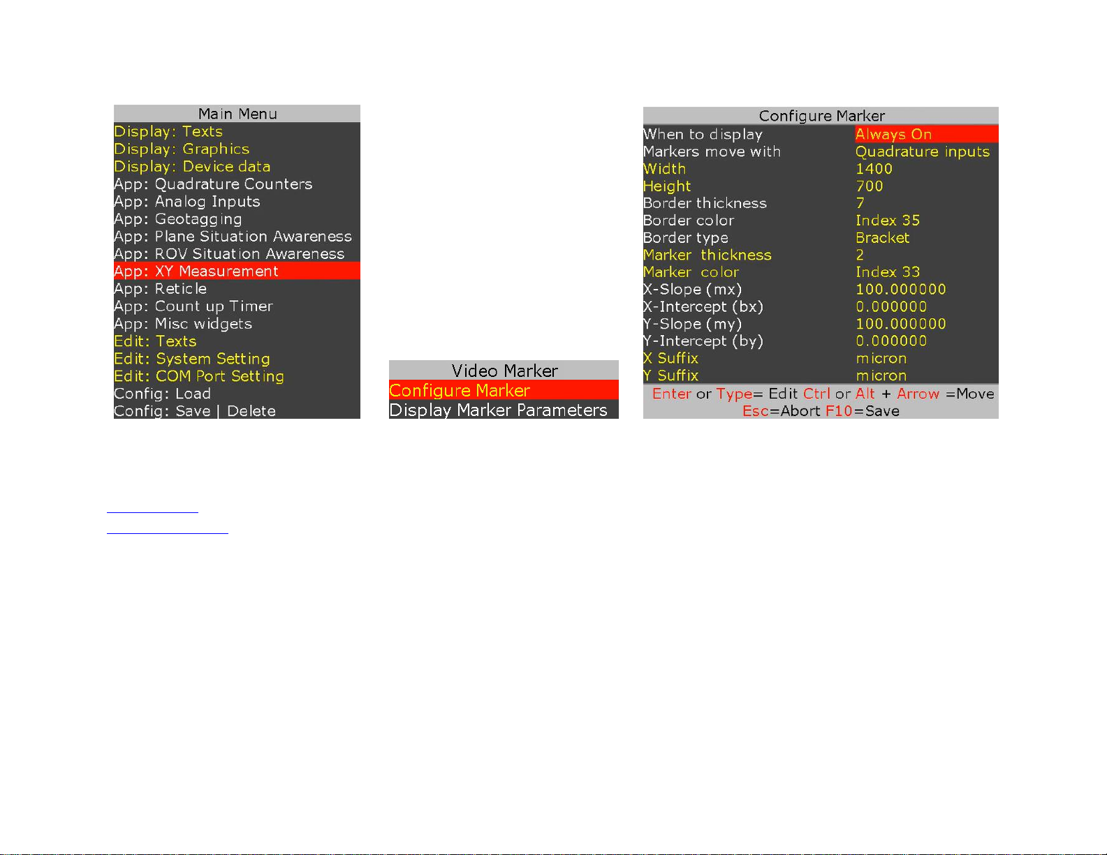
To customize the sample file to meet your needs, follow Figure 40 - Figure 42:
Figure 40
Figure 41 Figure 42
There are 4 options for X1, X2, Y1, Y2 marker movement:
Analog Inputs
Apply 0-3.3V to CH1-CH4
Quadrature Inputs
Connect incremental encoder switches to quadrature inputs# 1,2
RS232 Command
Send command $VL43,157,x1,x2,y1,y2*XX to set registers #157,158,159,160
Keyboard Arrow
Use ↕↔ to move 1-pixel resolution. Use Ctrl + ↕↔ to move 25 pixels
To quickly get familiar with this app, please watch our short tutorial video “Tutorial Video XY Measurement” on our web site.
Page 37
37
RETICLE
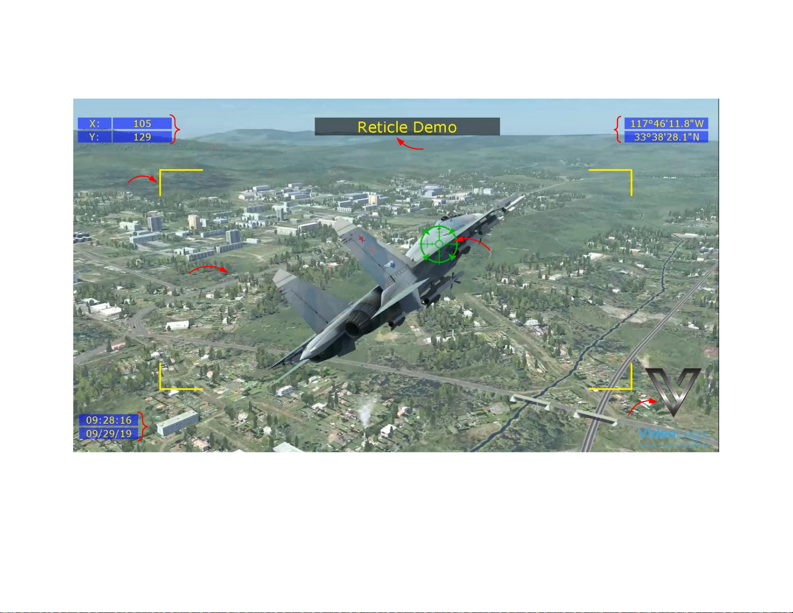
A sample Reticle file is provided with your PROTEUS. To load it, press F9, go to “Config: Load” and select “Reticle”.
2
5
6
6
6
1
3
4
1
Reticle position
Reticle X&Y position. Center is at 0,0
2
Reticle style
Reticle can be any PNG image, adjustable crosshair or square box. See examples below.
Reticle can be moved by via Analog inputs, quadrature inputs, RS232 command, arrow keys
3
Border
Border can be a bracket, box or none. Adjustable line width & color
4
Area
The width and height are adjustable up to 1920 x 1080
5
GPS
Latitude & Longitude
6
Misc. parameters
Title, Time & Date, Logo. Fully configurable by the user
Page 38
38
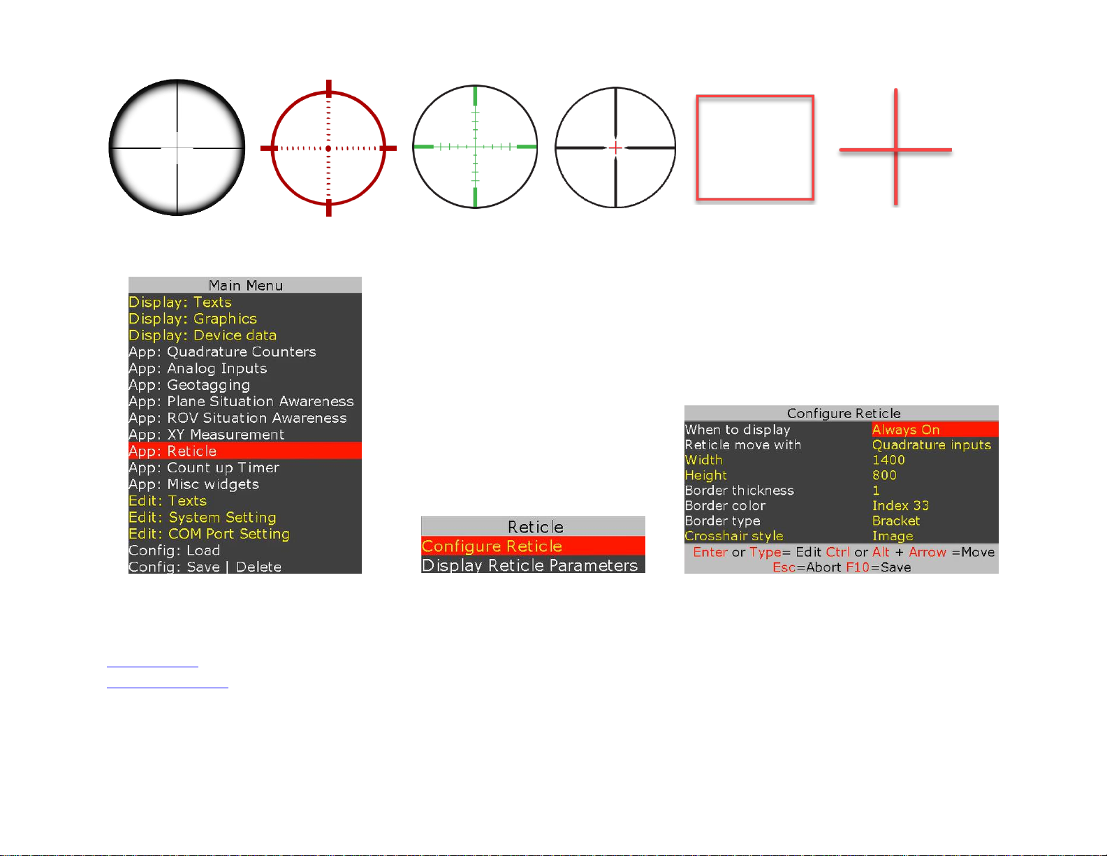
To customize the sample file to meet your needs, follow Figure 43 - Figure 45
Figure 43
Figure 44
Figure 45
There are 4 options for Reticle movement:
Analog Inputs
Apply 0..3.3V to CH1-CH2
Quadrature Inputs
Connect two incremental encoder switches to quadrature inputs# 1,2
RS232 Command
Send command $VL43,155,x,y*XX to set registers #155,156
Keyboard Arrow
Use ↕↔ to move 1-pixel resolution. Use Ctrl + ↕↔ to move 25 pixels
To quickly get familiar with this app, please watch our short tutorial video “Tutorial Reticle” on our web site.
Page 39
39
PLANE SITUATION AWARENESS
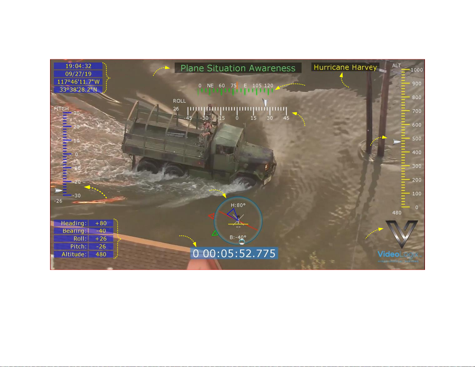
A sample Plane file is provided with your PROTEUS. To load it, press F9, go to “Config: Load” and select “Plane”.
2
4C
4B
1
7
3
5
6
4A
7
7
1
GPS data
Read from GPS attach to COM1 or COM2
2
Plane Situation Widget
Please see below for detail description
3
Compass
Rolling compass widget
4A, 4B, 4C
Sliders
4A depict pitch, 4B roll and 4C Altitude
5
Timer
A count up timer with msec resolution
6
CSV Sentence-A values
VAL1 = Heading, VAL2 = Bearing, VAL3 = Roll, VAL4=Pitch, VAL5 = Depth
7
Misc. parameters
Title, Logo. Fully configurable by the user
Page 40
40
PLANE SITUATION AWARENESS WIDGET
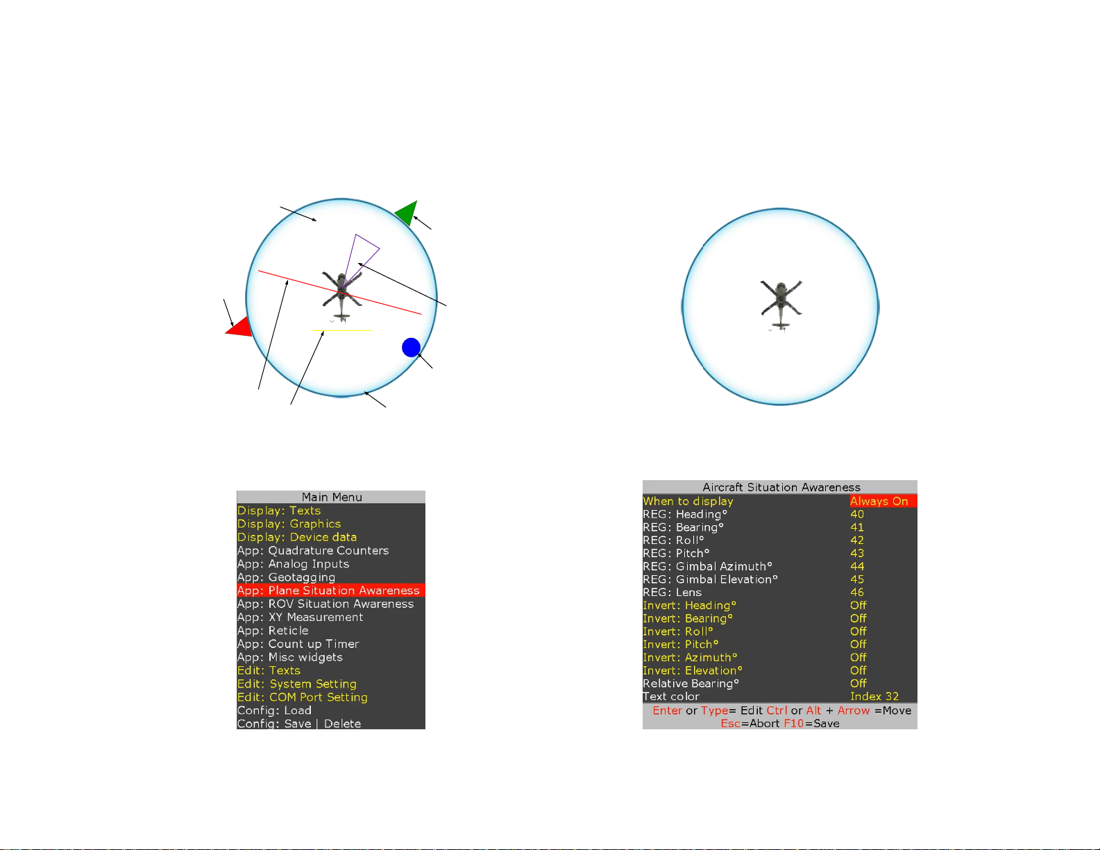
As shown in Figure 46, Plane situation awareness widget depicts parameters such as heading, bearing (relative or magnetic), roll, pitch, azimuth,
elevation. The size of the widget is governed by the background image shown in Figure 47. Larger image will result in a larger widget.
Background image resides on the microSD and can be replaced by a user-provided image for different size and look & feel. The image must be
named “Ring Plane”.
Background Image #9
H:100°
Current Heading
Pitch
Elevation
Azimuth
North
Roll
Waypoint
B:40°
Figure 46
Figure 47
Follow Figure 48 - Figure 49 to configure the widget.
Figure 48
Figure 49
Page 41
41
Follow Figure 49 to specify what register are associated with each parameter. For example, table below shows available options for heading:
Register # associated with Heading
Description
102
Heading is provided by attaching Garmin GPS modem to a COM port
114
Heading is provided by attaching Vector NAV INS sensor to a COM port
40
Heading is provided by transmitting a CSV sentence A to a COM port. Heading would be VAL1
00
Do not display heading
The device (GPS, INS ...) specific registers are updated automatically when it is connected to PROTEUS. When the content of a register changes,
any widget (text or graphic) that is linked to that register is automatically updated.
The content of any register can also be changed by sending Set Register Command. Assuming register 40 is linked to heading, command below
will set the heading to 85°. Therefore, all widgets linked to register 40 will be updated automatically.
$VL43,40,85*XX
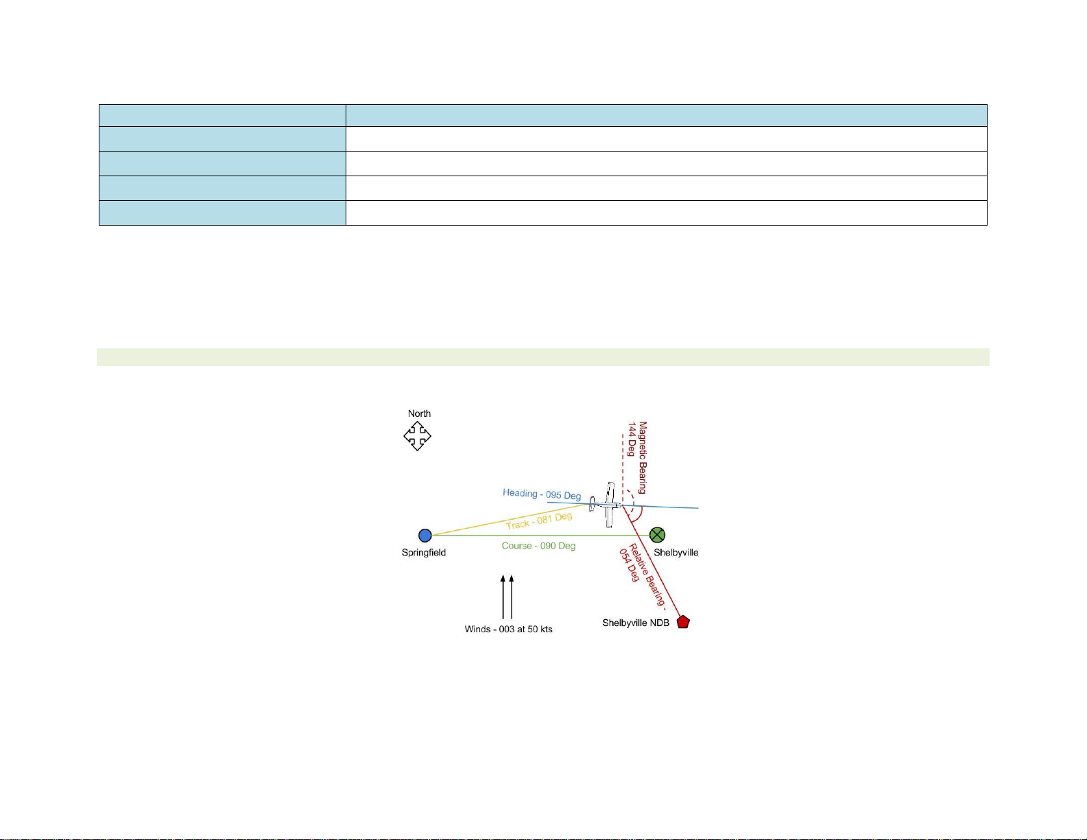
Figure 50 demonstrates the relation between heading, relative vs magnetic bearing:
Figure 50
To customize the sample file to meet your needs, please visit the corresponding section in this document to learn about the specifics.
Page 42
42
ROV SITUATION AWARENESS
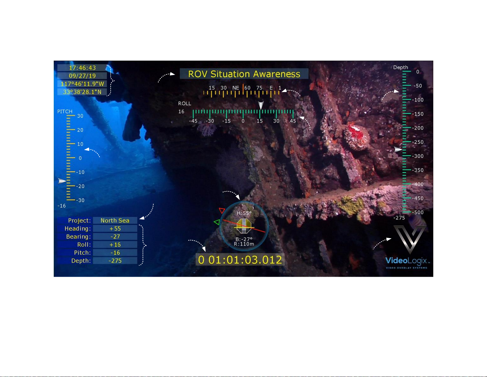
A sample ROV file is provided with your PROTEUS. To load it, press F9, go to “Config: Load” and select “ROV”.
2
4C
4B
1
7
3
5
6
4A
7
7
1
GPS date
Read from GPS attach to COM1
2
ROV Situation Widget
Please see below for detail description
3
Compass
Rolling compass widget
4A, 4B, 4C
Sliders
4A depict pitch, 4B roll and 4C Depth
5
Timer
A count up timer with msec resolution
6
CSV Sentence-A values
VAL1 = Heading, VAL2 = Bearing, VAL3 = Roll, VAL4=Pitch, VAL5 = Depth
7
Misc. parameters
Title, Logo. Fully configurable by the user
Page 43
43
ROV SITUATION AWARENESS WIDGET
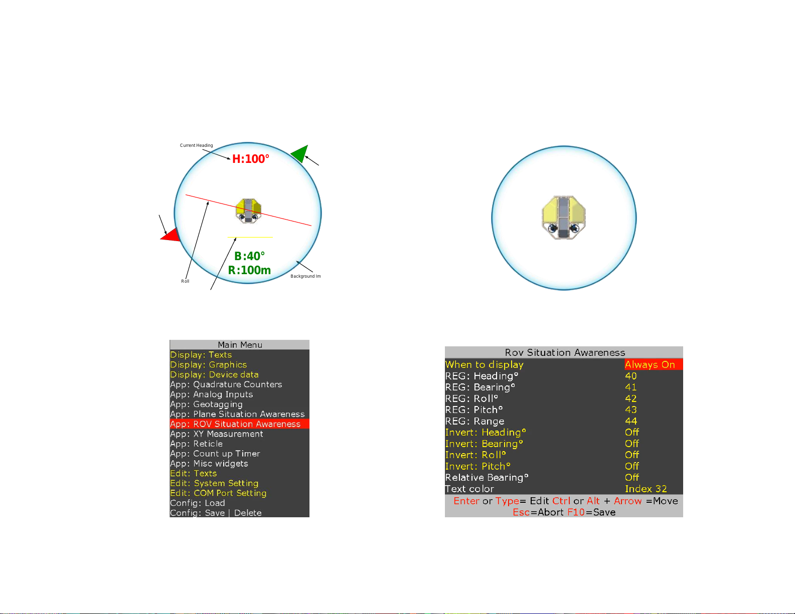
As shown in Figure 51, ROV situation awareness widget depicts parameters such as heading, bearing (relative or magnetic), range to target, roll
and pitch. The size of the ROV widget is governed by the background image shown in Figure 52. Larger image will result in a larger widget.
Background image resides on the microSD and can be replaced by a user-provided image for different size and look & feel. The image must be
named “Ring Rov”.
Background Image #10
H:100°
Current Heading
Pitch
North
Roll
Target
B:40°
R:100m
Figure 51
Figure 52
Follow Figure 53-Figure 54 to configure the widget.
Figure 53
Figure 54
Page 44
44
Follow Figure 54 to specify what register is associated with each parameter. For example, table below shows available options for heading:
Register # associated with Heading
Description
80
Heading is provided by attaching Garmin GPS modem to PROTEUS COM port
110
Heading is provided by attaching Vector NAV INS sensor to PROTEUS COM port
40
Heading is provided by transmitting a CSV sentence A to a COM port. Heading would be 1st variable.
00
Do not display heading
The device (GPS, INS ...) specific registers are updated automatically when it is connected to PROTEUS. When the content of a register changes,
any widget (text or graphic) that is linked to that register is automatically updated.
The content of any register can also be changed by sending Set Register Command. Assuming register 40 is linked to heading, command below
will set the heading to 85°. Therefore, all widgets linked to register 40 will be updated automatically.
$VL43,40,85*XX
To customize the sample file to meet your needs, please visit the corresponding section in this document to learn about the specifics.
Page 45
45
SLIDERS
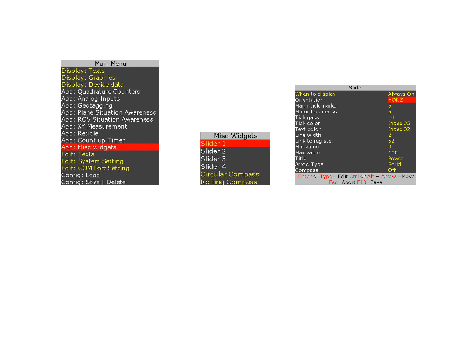
PROTEUS provides 4 fully configurable sliders. Follow Figure 55- Figure 57 to configure the sliders.
Figure 55
Figure 56
Figure 57
Slider must be linked to a register. Registers are updated via associated sensors or through RS232 commands. When the linked register receives a new
value, associated slider is automatically updated.
Assuming slider is linked to register #40, RS232 command $VL43,40,30*XX will set slider to 30.
Page 46
46
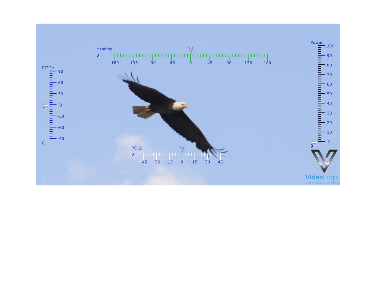
Figure 58
Page 47
47
COMPASS
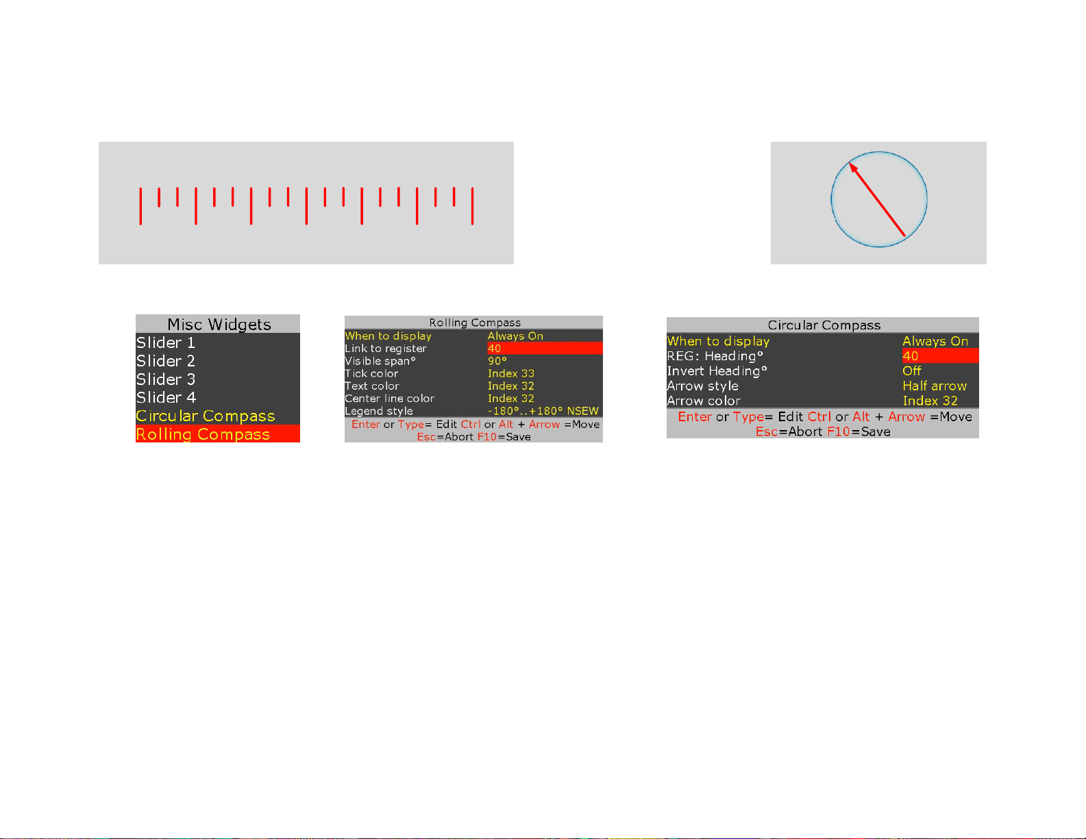
PROTEUS provides a rolling compass and simple circular compass as shown below.
N 15 30 NE-15-30NW
Follow Figure 59 - Figure 61 to configure each compass
Figure 59 Figure 60
Figure 61
Rolling compass provides 4 visible spans (30⁰, 45⁰, 60⁰, 90⁰) with 4 different legends described below:
• 0..360⁰
• 0..360⁰ NSEW
• -180⁰...+180⁰
• -180⁰...+180⁰ NSEW
The size of the circular compass widget is governed by its background image. Larger image will result in a larger compass. Background
image resides on the microSD and can be replaced by a user-provided image for different size and look & feel. The image must be named
“Ring100”.
Page 48
48
COUNT UP TIMER
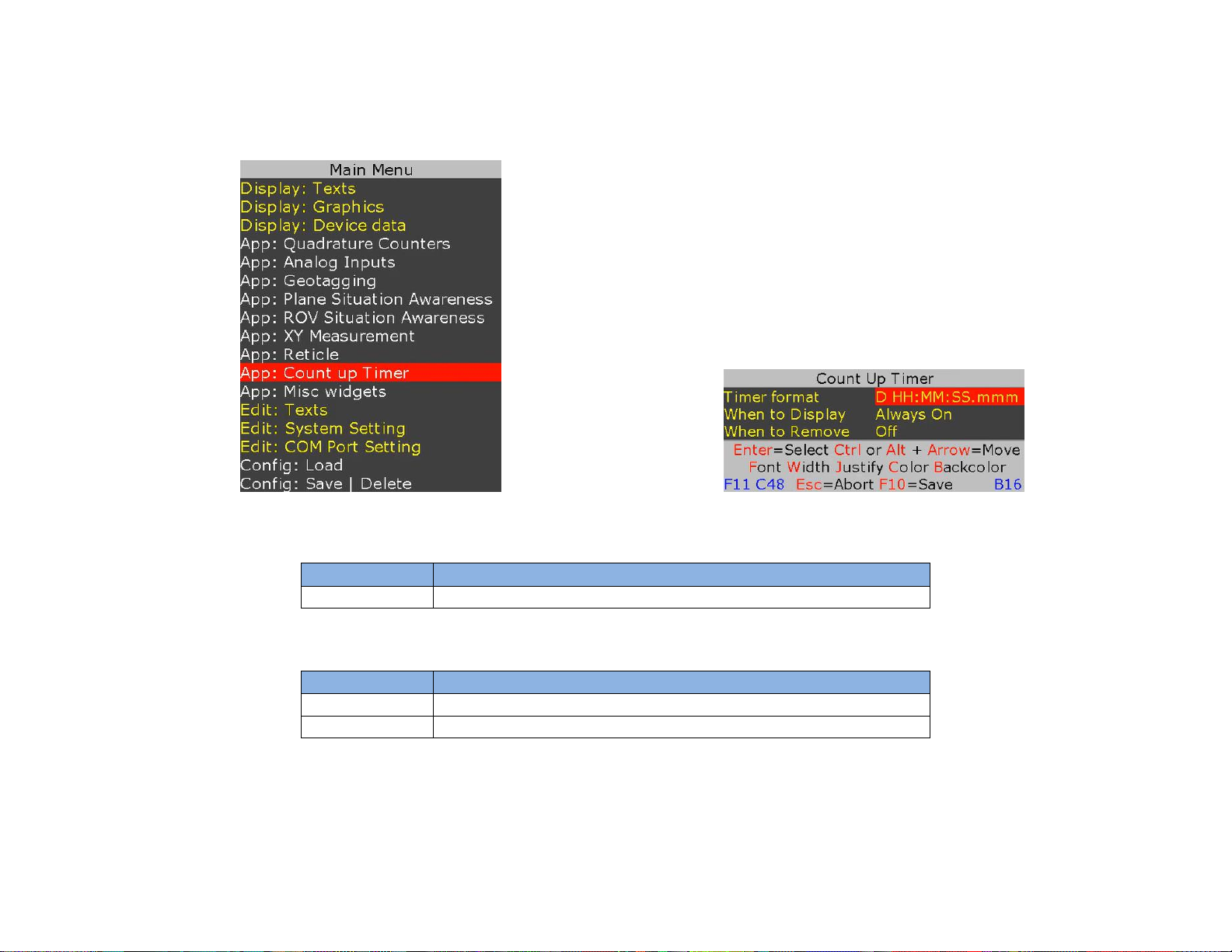
PROTEUS provides Count Up timer. Follow Figure 62-Figure 63 to configure the timer.
Figure 62
Figure 63
CLOCK SOURCE
Source
Description
Internal 27MHz
Source for 1msec pre-scaler
EXTERNAL CONTROLS
GPI
Description
IN1
0 = Pause Timer, 1 = Resume Timer
IN2
0 = Reset Timer. Reset occurs within 10nsec.
TIMER FORMAT
Timer format is “D HH:MM:SS.mmm” where D is number of days and mmm is milliseconds
Page 49
49
GEOTAGGING & KML GENERATION
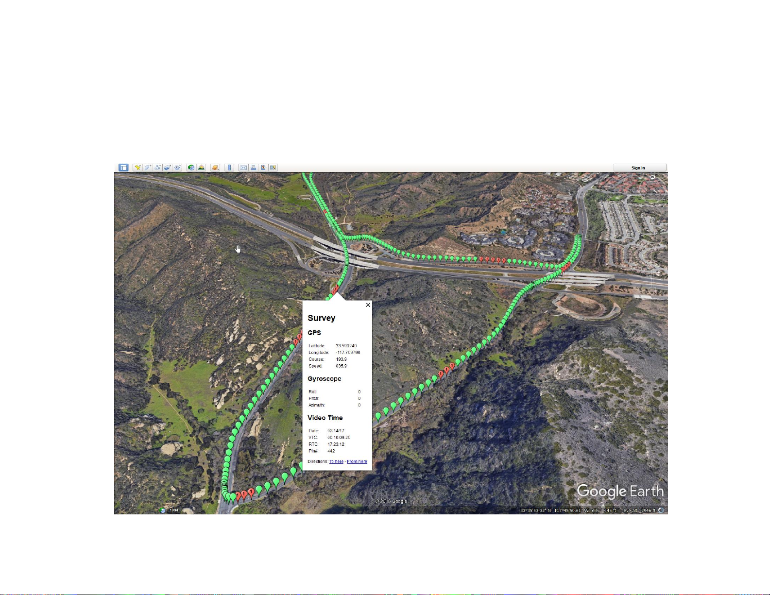
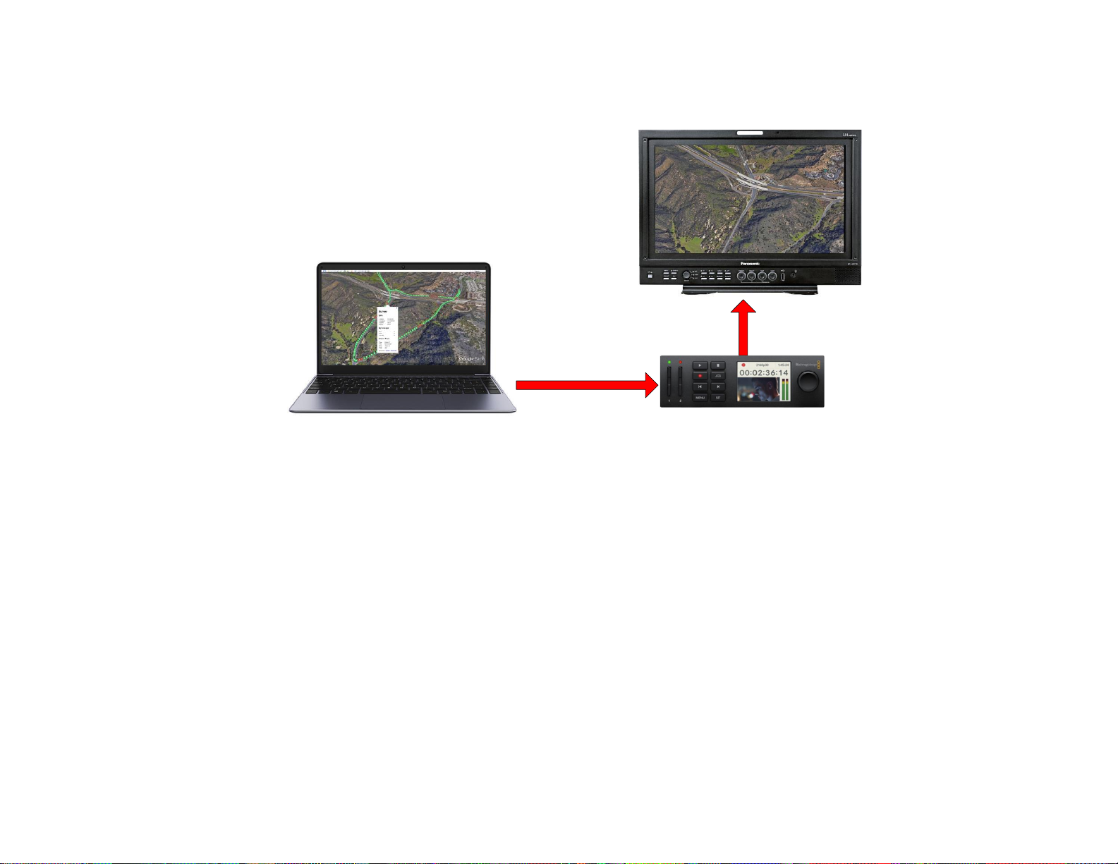
Geotagging is the process of syncing geographical data such as latitude and longitude coordinates, time and date, video time code (VTC),
altitude, bearing, camera gyro (pitch, roll, azimuth) etc. to your video in real time. This produces geotagged media (KML file) that can be
viewed in Google Earth so you can see the exact location where video was taken.
During geo recording, operator can drop unique place markers (red marker #1, #2) to bring attention to monitoring staff.
During playback, monitoring staff can click on any place marker and jump to the exact instant in the video.
Figure 64
Page 50
50
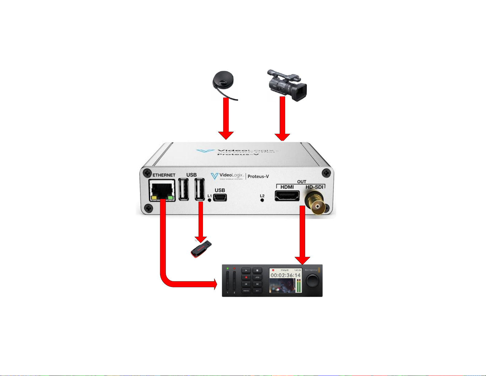
RECORDING SETUP
GPS
RJ45
Video In
Video Out
KML Storage
Page 51
51
PLAYBACK SETUP
Google Earth loaded with
KML file
RJ45
Video
CONFIGURATION
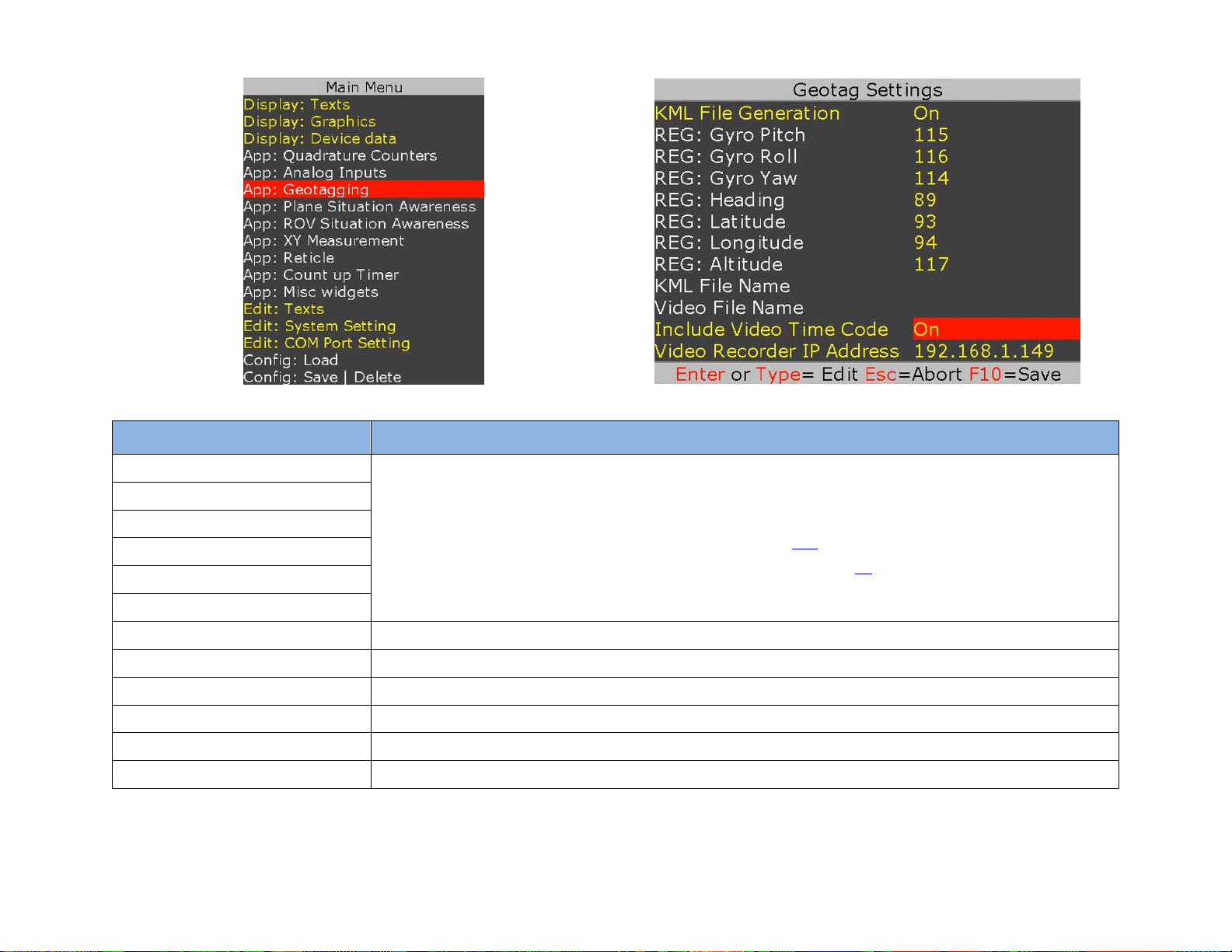
Press F9 and follow figures below to configure the geotagging.
Page 52
52
Settings
Description
REG: Gyro Pitch
Enter PROTEUS register# where values are read from.
For example, for Pitch:
• If a Vector NAV IMU is attached to PROTEUS, enter 115
• If user provides pitch value via CSV Sentence-A (VAL2) enter 41
• If not required, enter 0
REG: Gyro Roll
REG: Gyro Azimuth
REG: Heading
REG: Latitude
REG: Longitude
KML File Name
This field will be used in the future release
Video File Name
This field will be used in the future release
F1/F2 Control Video Recording
Video recording can be control directly or via keyboard. F1 = Start, F2 = Stop
Log KML when moving only
To reduce file size, recording can be enabled only when in motion
Include Video Time Code
If enable, video recorded must be connected to PROTEUS via Ethernet cable
Video Recorder IP address
Enter IP address of the video recorder
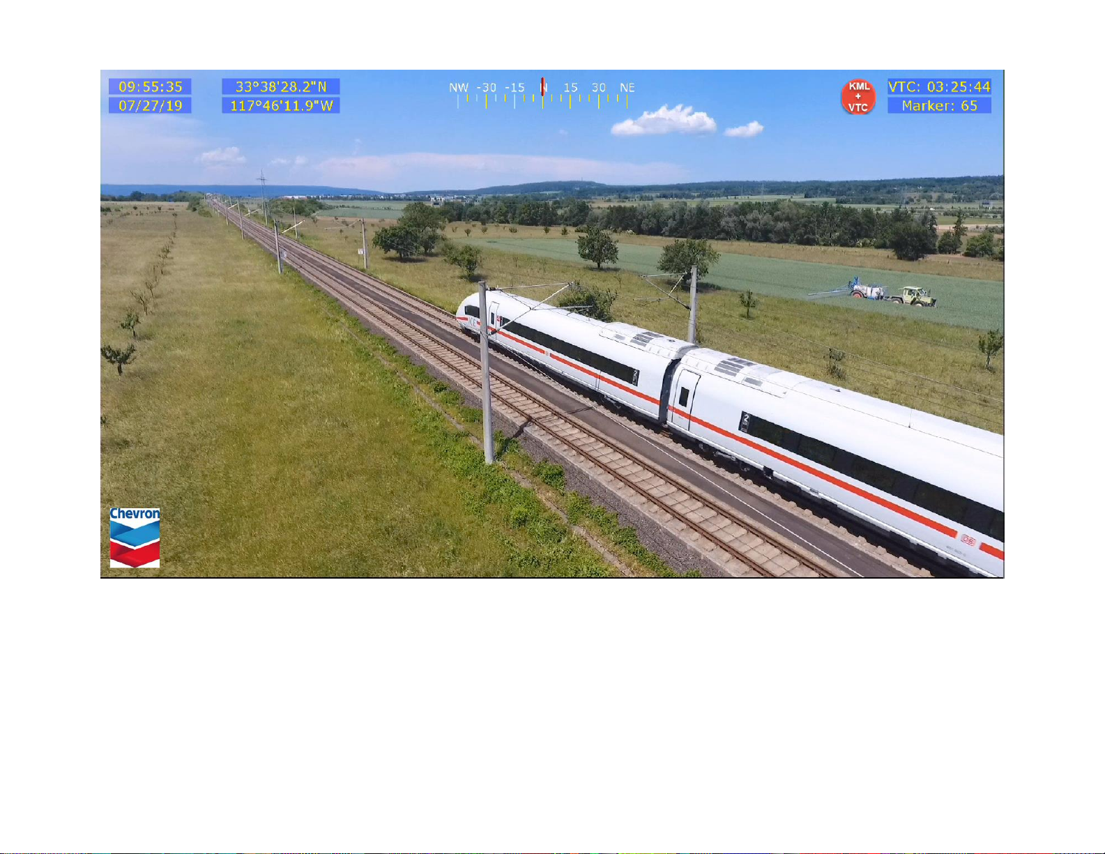
You can easily customize what information is over laid on your video in real time. In the sample screen shown in Figure 65:
Page 53

53
• GPS time, date, latitude and longitude are superimposed on the upper left.
• A rolling compass in the center.
• Current Video Time Code (VTC) and current place marker # on the upper right.
As show in Figure 64, the default place maker is green. When F3 or F4 is pressed, red place marker #1 or #2 is inserted once. Alternative place
markers can be used to quickly bring attention to locations requiring in depth analysis.
To start KML recording, press F1.
To stop KML recording, press F2.
As show in Figure 64, during KML recording, the red icons located on the upper right flashes once per second to confirm recording is in process.
Page 54
54
Figure 65
Page 55

55
PROTEUS COMMANDS
Aside from supporting various connected devices, PROTEUS provides over 30 powerful commands to overlay crisp and clear texts, graphics and
telemetry generated information into an incoming HD & SD video in real time. Refer to the Software Communication Spec (SCS) for the detail
description of each command.
TRANSMIT A COMMAND SCRIPT
1. Connect PROTEUS to your monitor. Connect RS232 cable from your PC to the PROTEUS. Power on PROTEUS.
2. Run PROTEUSApp located in folder C:\VideoLogix-V\utility.
3. Use File, Select Com Port to assign a com port.
4. Go to "Demo/Tutorial" tab.
5. Click Run Script Now button and load C:\VideoLogix-V\Script\0-TestCommands.
6. A demo should appear on your video monitor.
Page 56

56
PROTEUS REGISTERS
PROTEUS system contains a collection of registers used for configuring the system and accessing the data it produces. These registers may be read
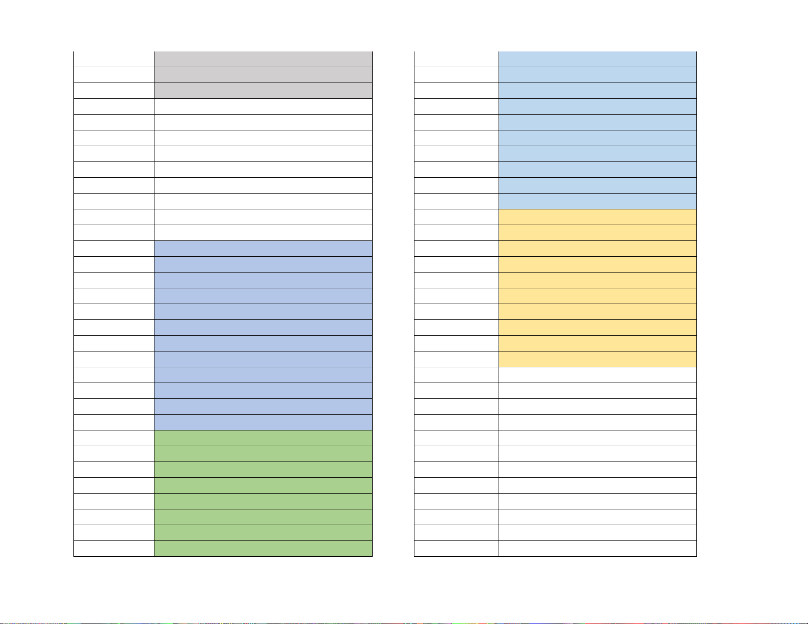
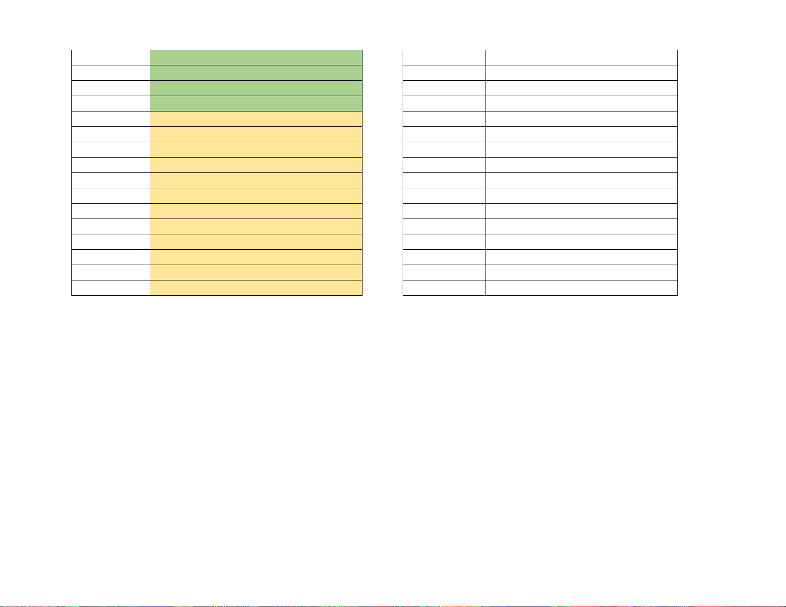
or written to using the Read Register and Write Register commands (refer to SCS for detail). The table in Appendix G provides a quick reference
for all the registers and their associated properties. The device specific (Cineflex, IMU, GPS ...) registers are automatically updated when the
associated device is connected to PROTEUS. Widgets that are linked to a register are updated automatically when the content of the register
changes.
Page 57
57
SPECIFICATIONS
MAXIMUM INPUT VOLTAGE
Min (DCIN)
Max (DCIN)
Power
6VDC
42VDC
4 watts
INPUT CONNECTOR
DC power jack is standard 2 conductors, center pin positive, 2.1mm ID, 5.5mm OD.
ENVIRONMENTAL
Specifications
Min
Max
Operating Temperature
0° C
65° C
Humidity
10-90% RH Non-Condensing
Storage Temperature
-40° C
115° C
WEIGHT & DIMENSION
Weight
1 lbs.
Dimension
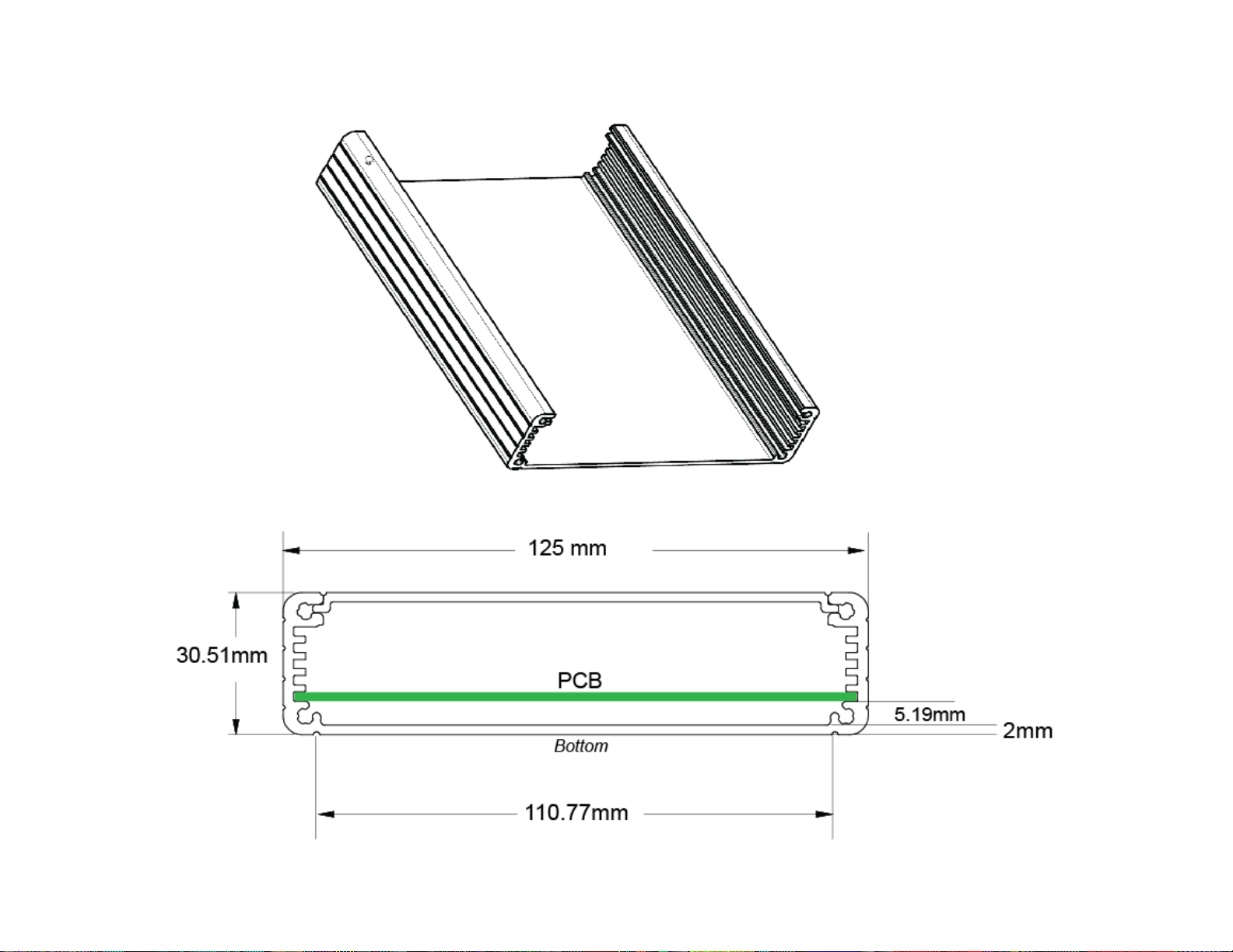
125.30 x 105.23 x 30.51 (mm)
FRONT PANEL LED
PROTEUS provides 3 LED’s in the front & rear panel.
LED
Description
L1
Flashes when a RS232 message is received
L2
Flashes when system is working properly
L3
Flashes when FPGA is working properly
Ethernet LED
Flashes when there is a write to the USB flash drive
Page 58
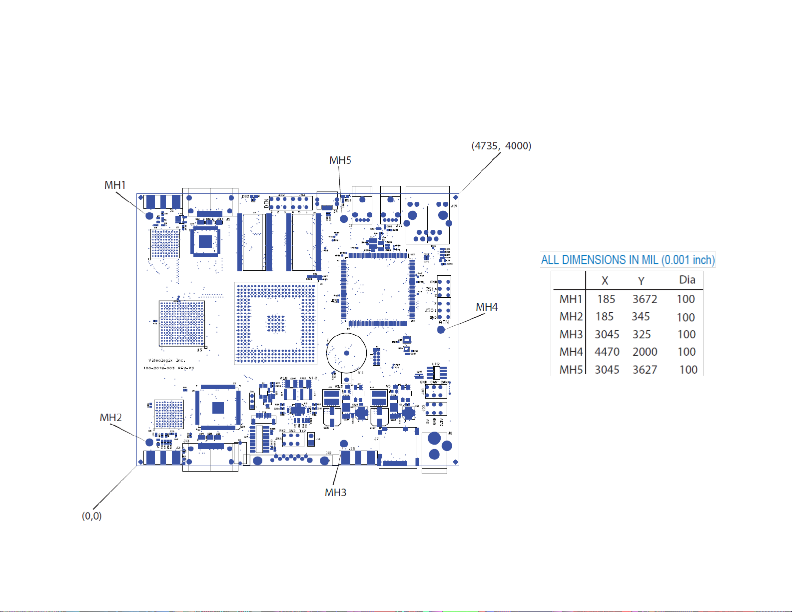
58
PCB DIMENSION
Page 59
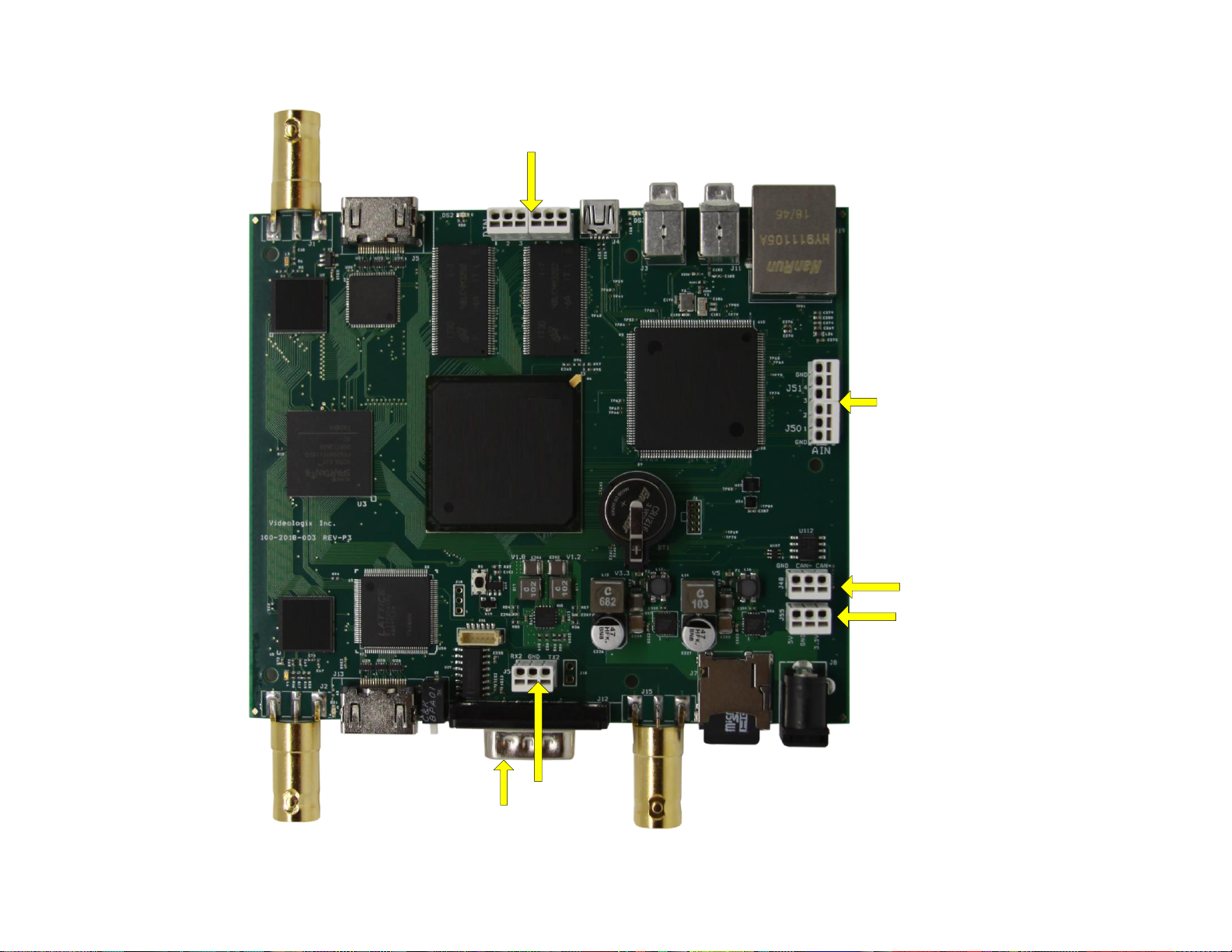
59
COM1
COM2
CAN
microSD
4 x Analog
Inputs
Ethernet
2 x USB
HOST
1 x USB
DEVICE
2 x Quadrature
Inputs
5V, 3.3V
GND
HDMI in
SDI in
HDMI out
SDI out
Power
IRIG in
Composite in
Page 60
60
ENCLOSURE DIMENSION
Page 61
61
APPENDIX A – KEYBOARD COMMANDS
KEYBOARD COMMANDS
Keyboard command
Description
F1
KML: Start recording
F2
KML: Stop recording
F3
KML: Drop place marker #1
F4
KML: Drop place marker #2
F8
Shortcut to “Edit: User Texts”
F9
Launch Main-Menu
F10
Save changes & exit Sub-Menu
ESC
Abort changes and exit Sub-Menu
Enter or Ctrl + Enter
Select an item from the picklist i.e. COM1, COM2…
Alt + G
Draw 60 x 60 pixel gridlines on video
Alt + H
Help
KEYBOARD SHORTCUTS
The following keystrokes are used to format the text superimposed on video.
Browse
Forward Reverse
Description
C
or
Ctrl + C
Color: Change text foreground color
F
or
Ctrl + F
Font: Change font type
W
or
Ctrl + W
Width: Change width of the field
J
or
Ctrl + J
Justify text: Left, center or right justification text within field
B
or
Ctrl + B
Background color: Change text background color
Ctrl + Arrow
or
Alt + Arrow
Move text location. Hold Ctrl to move the field 30 pixels and Alt to move the field 2 pixels.
Page 62
62
APPENDIX B – UPDATING FIRMWARE
This section assumes you have already installed Renesas Flash Programmer. If not, please follow instruction in Appendix C.
1. Toggle CFG switch in the rear panel to the lower position
2. Cycle power to PROTEUS
3. Connect mini USB cable from your PC to PROTEUS
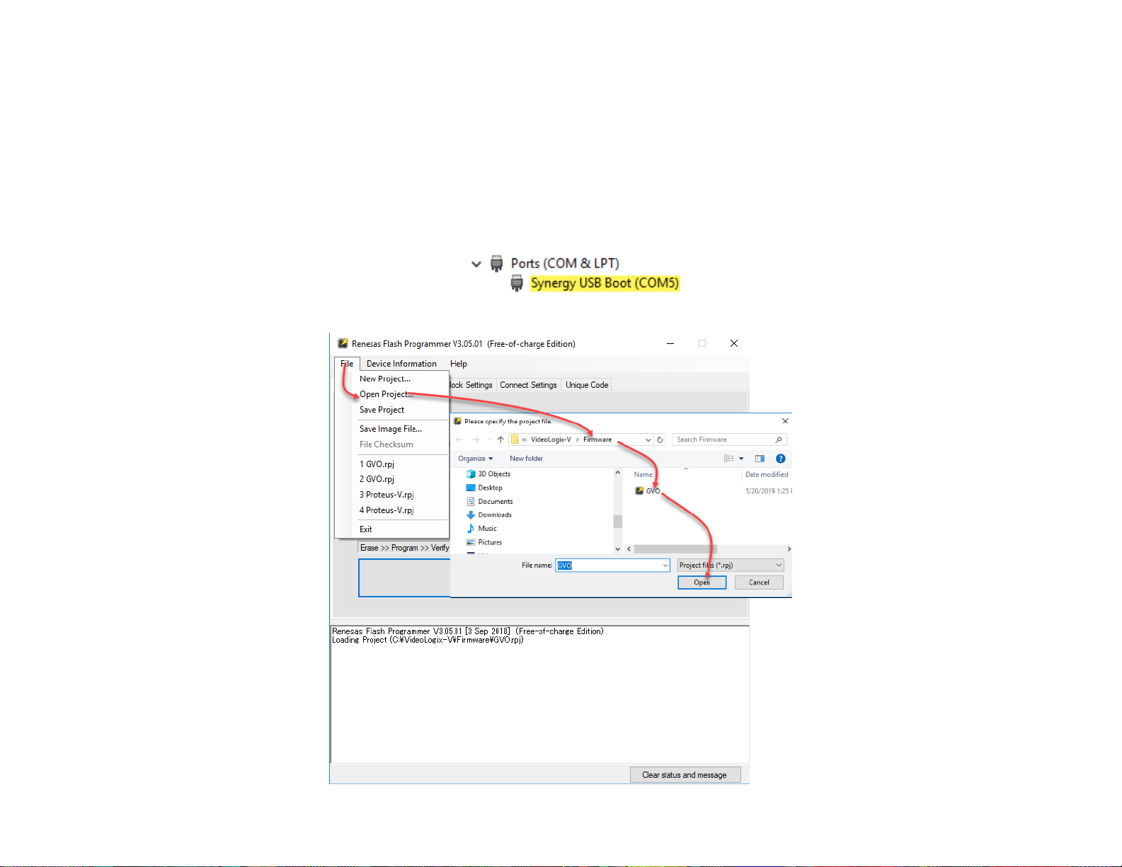
4. Your PC should acknowledge PROTEUS with a beep. Alternatively, Device manage will add the following:
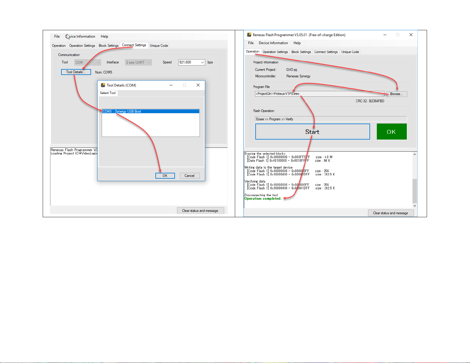
5. Start Renesas Flash Programmer and Follow instructions below:
Page 63
63
6. After ‘Operation completed’, Toggle CFG switch in the rear panel to the upper position
7. Cycle power to PROTEUS and you are done.
Page 64
64
APPENDIX C – INSTALL RENESAS FLASH PROGRAMMER
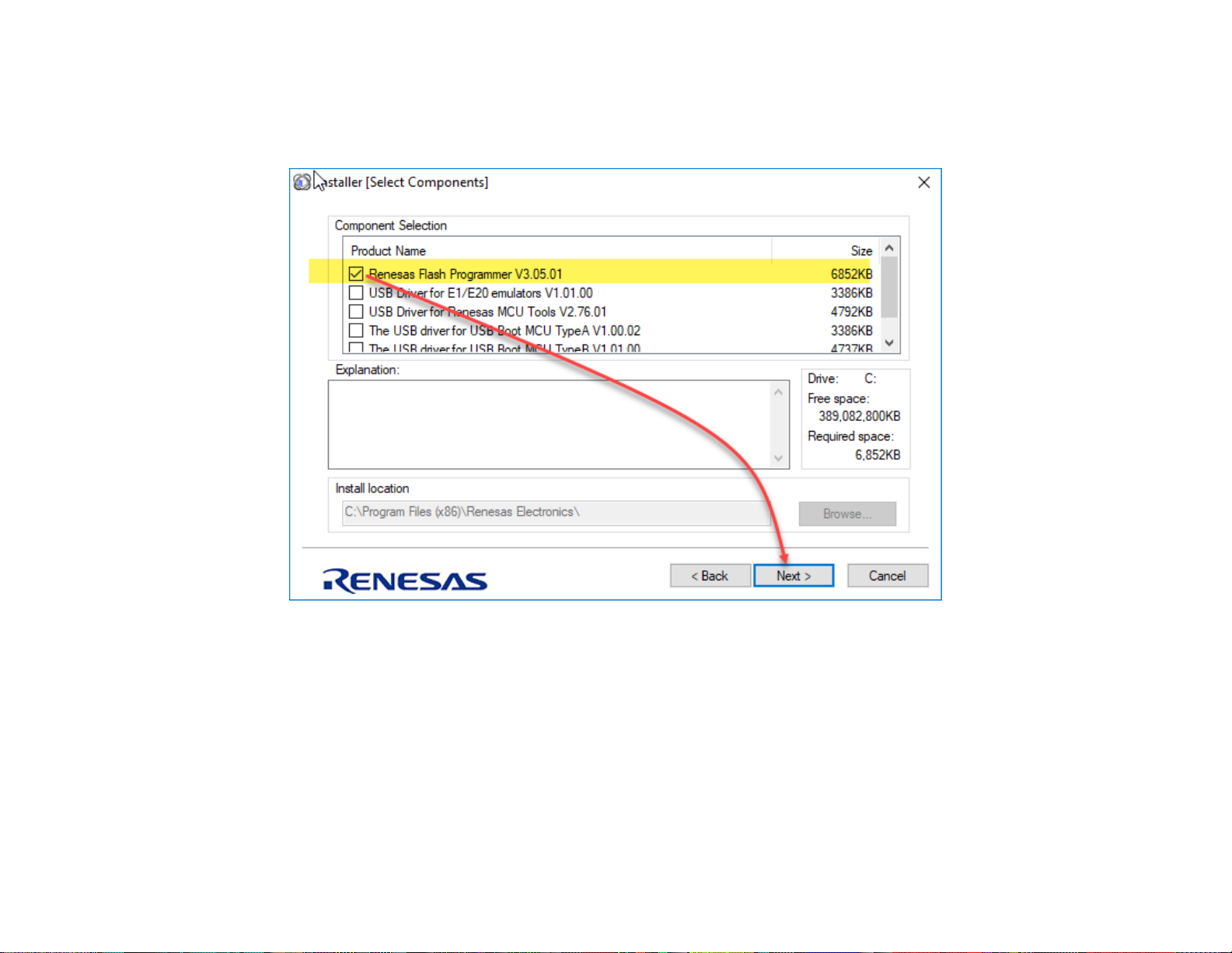
Launch program ‘Renesas_Flash_Programmer_Package_V30501’ and follow instruction below. This program is in utility folder on microSD card.
Page 65
65
APPENDIX D – IMAGES
PROTEUS can display PNG and JPG images.
JPG
Image width & height divisible by 32. For example, 32 x 32 or 64 x 32 or 224 x 192, 320 x 64, etc.
PNG
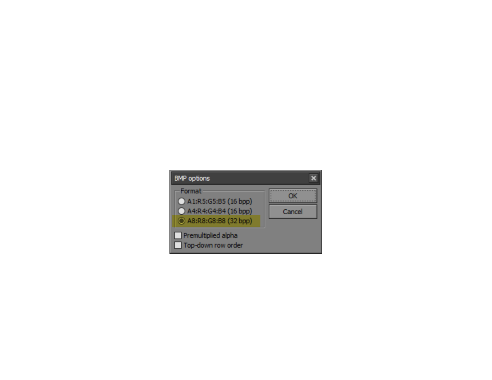
PNG image must be converted to 32-bit BMP using Pixelformer utility. This utility will preserve pixel level alpha blending. This program is in
utility folder on microSD card. Use File-import to open PNG file and File-export to create the BMP file. When prompted, select A8:R8:G8:B8 as
shown below.
LOCATION
Store images in the folder Images on the microSD card.
Page 66

66
APPENDIX E – CREATE CUSTOM FONTS
FONT0 through FONT7 can be customized by the user. To create your own fonts, follow steps below:
1. Start PROTEUSApp. This app is in utility folder on microSD card.
2. Go to Font + Bitmask tab.
3. Click Select Font button and select your desire font type & style.
4. Click Create Font File button.
5. Select your desire ISO Character set template from C:\videologix-V\Fonts\ISO8859-9 Latin1.txt
6. Type a file name for your font and press save.
7. Your new font will be stored in folder C:\videologix-V\Fonts\
8. Edit file FontList.txt to add your new font file.
9. Copy FontList.txt and new font file to the folder ‘Fonts’ on microSD card.
Page 67
67
APPENDIX F – TERMINAL BLOCKS
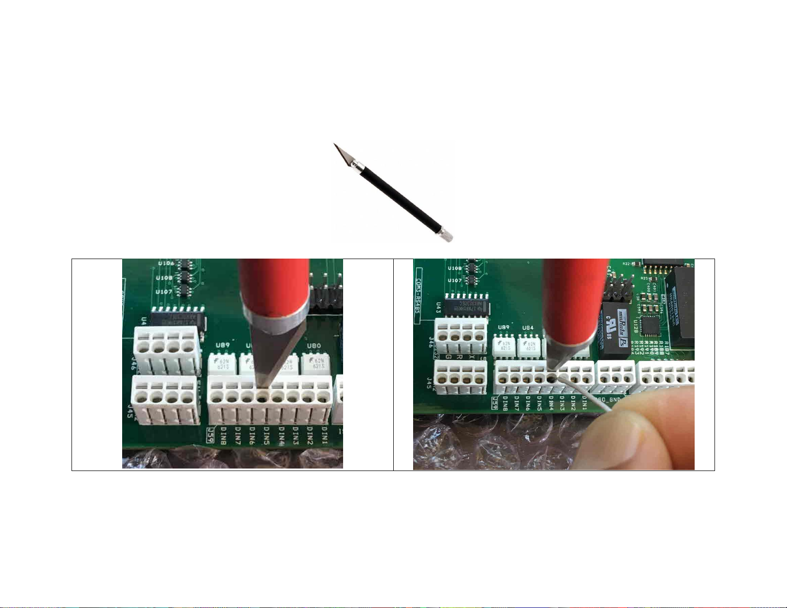
Care must be taken when inserting wire into terminal blocks. Do not insert thick screwdriver into terminal block as it will permanently damage the
internal spring-loaded contacts. In general, any blade with 0.4mm x 2mm cross section is appropriate. Digikey P#1205202 is factory approved.
We have learned that X-ACTO Knife shown below works best.
Page 68
68
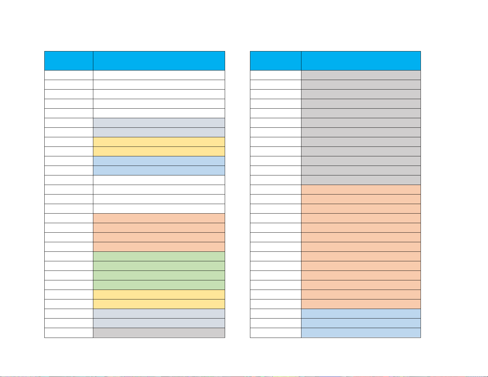
APPENDIX G – REGISTER DESIGNATION
Register ID
Designation
Register ID
Designation
0
-
76
PM_TOKEND1,
1
PM_STRING,
77
PM_TOKEND2,
2
PM_BITMASK,
78
PM_TOKEND3,
3
PM_VIDEO_MOD,
79
PM_TOKEND4,
4
PM_UTC_OFFSET,
80
PM_TOKEND5,
5
PM_RTC_TIME,
81
PM_TOKEND6,
6
PM_RTC_DATE,
82
PM_TOKEND7,
7
PM_IRIG_TIME,
83
PM_TOKEND8,
8
PM_IRIG_DATE,
84
PM_TOKEND9,
9
PM_NTP_TIME,
85
PM_TOKEND10,
10
PM_NTP_DATE,
86
PM_TOKEND11,
11
PM_ATC_TIME,
87
PM_TOKEND12,
12
PM_DOWN_TIMER,
88
PM_GPS_ALTITUDE,
13
PM_UP_TIMER,
89
PM_GPS_COG,
14
-
90
PM_GPS_SPEED,
15
PM_AN_RAW1,
91
PM_GPS_TIME,
16
PM_AN_RAW2,
92
PM_GPS_DATE,
17
PM_AN_RAW3,
93
PM_GPS_LAT_D,
18
PM_AN_RAW4,
94
PM_GPS_LON_D,
19
PM_AN_MAP1,
95
PM_GPS_LAT_DM,
20
PM_AN_MAP2,
96
PM_GPS_LON_DM,
21
PM_AN_MAP3,
97
PM_GPS_LAT_DMS,
22
PM_AN_MAP4,
98
PM_GPS_LON_DMS,
23
PM_QUAD_RAW1,
99
PM_GPS_SEQUENCE,
24
PM_QUAD_RAW2,
100
PM_GPS_ID,
25
PM_QUAD_MAP1,
101
PM_GPS2_ALTITUDE,
26
PM_QUAD_MAP2,
102
PM_GPS2_COG,
27
PM_COUNTER1,
103
PM_GPS2_SPEED,
Page 69
69
28
PM_COUNTER2,
104
PM_GPS2_TIME,
29
PM_COUNTER3,
105
PM_GPS2_DATE,
30
PM_COUNTER4,
106
PM_GPS2_LAT_D,
31
PM_GPI, 107
PM_GPS2_LON_D,
32
PM_SPAR1,
108
PM_GPS2_LAT_DM,
33
PM_SPAR2,
109
PM_GPS2_LON_DM,
34
PM_SPAR3,
110
PM_GPS2_LAT_DMS,
35
PM_eCompass,
111
PM_GPS2_LON_DMS,
36
PM_HEADERA,
112
PM_GPS2_SEQUENCE,
37
PM_HEADERB,
113
PM_GPS2_ID,
38
PM_HEADERC,
114
PM_IMU_HEADING,
39
PM_HEADERD,
115
PM_IMU_PITCH,
40
PM_TOKENA1,
116
PM_IMU_ROLL,
41
PM_TOKENA2,
117
PM_IMU_HEIGHT,
42
PM_TOKENA3,
118
PM_IMU_LAT,
43
PM_TOKENA4,
119
PM_IMU_LON,
44
PM_TOKENA5,
120
PM_IMU_TIME,
45
PM_TOKENA6,
121
PM_IMU_DATE,
46
PM_TOKENA7,
122
PM_IMU_LAT_DMS,
47
PM_TOKENA8,
123
PM_IMU_LON_DMS,
48
PM_TOKENA9,
124
PM_CINEFLEX_AZIMUTH,
49
PM_TOKENA10,
125
PM_CINEFLEX_ELEVATION,
50
PM_TOKENA11,
126
PM_CINEFLEX_ROLL,
51
PM_TOKENA12,
127
PM_CINEFLEX_FOCUS,
52
PM_TOKENB1,
128
PM_CINEFLEX_ZOOM,
53
PM_TOKENB2,
129
PM_CINEFLEX_IRIS,
54
PM_TOKENB3,
130
PM_CINEFLEX_TELE,
55
PM_TOKENB4,
131
PM_CINEFLEX_PAN,
56
PM_TOKENB5,
132
PM_ALTIMETER,
57
PM_TOKENB6,
133
PM_VSPEED,
58
PM_TOKENB7,
134
PM_MWV_ANGLE,
59
PM_TOKENB8,
135
PM_MWV_REFERENCE,
Page 70
70
60
PM_TOKENB9,
136
PM_MWV_SPEED,
61
PM_TOKENB10,
137
PM_MWV_UNIT,
62
PM_TOKENB11,
138
PM_DBT_DEPTH,
63
PM_TOKENB12,
139
PM_DPT_DEPTH,
64
PM_TOKENC1,
140
PM_DPT_OFFSET,
65
PM_TOKENC2,
141
PM_DPT_RANGE,
66
PM_TOKENC3,
142
PM_MTW_TEMPRATURE,
67
PM_TOKENC4,
143 68
PM_TOKENC5,
144 69
PM_TOKENC6,
145 70
PM_TOKENC7,
146 71
PM_TOKENC8,
147 72
PM_TOKENC9,
148 73
PM_TOKENC10,
149 74
PM_TOKENC11,
150 75
PM_TOKENC12,
151
 Loading...