

Videoline MC-2620C, MC-2620E, MC-2621C, MC-2622C, MC-2621E Installation Instructions Manual
...
Videoline
Super Nite-Vision
OSD B/W CCD Camera
MC-2620 series
MC-2620C/2620E
MC-2621C/2621E
MC-2622C/2622E
INSTALLATION INSTRUCTIONS
To ensure optimum performance of this CCD camera, please carefully read
all the instructions before installing. Incorrect operation or setting may result
in inferior picture quality.

2
CONTENTS
1. General................................................................................................................. 3
2. Descriptions......................................................................................................... 3
3. Lens Connections................................................................................................5
3.1 Video drive auto iris lens (with EE amp)......................................................... 5
3.2 DC drive auto iris lens (without EE amp)........................................................ 5
3.3 Manual or fixed iris lens.................................................................................. 5
4. OSD Setup ...........................................................................................................6
4.1 OSD Control Buttons ...................................................................................... 6
4.2 CP-01 Remote Controller................................................................................ 6
4.3 RS-232 Connection......................................................................................... 6
5. Setup Menu..........................................................................................................7
6. CAMERA ID-Camera title setting ........................................................................ 8
6.1 Selecting character......................................................................................... 8
6.2 Editing camera title ......................................................................................... 8
6.3 Setting title position ........................................................................................ 8
6.4 Setting title display.......................................................................................... 8
7. LIGHT CNTL – Exposure mode setting............................................................... 9
7.1 AES Mode....................................................................................................... 9
7.2 AES LOW Mode............................................................................................ 12
7.3 Auto IRIS Mode............................................................................................. 12
7.4 Auto IRIS+SHUTTER Mode ......................................................................... 13
7.5 ME (Manual Exposure) Mode....................................................................... 13
8. PICTURE – Picture performance setting .......................................................... 13
8.1 VIDEO setting ............................................................................................... 13
8.2 APERTURE setting........................................................................................ 14
8.3 GAMMA setting............................................................................................. 14
9. DISPLAY – Video display mode setting............................................................ 14
10. OPD WINDOW – Optical detection window adjustment .................................. 15
11. MISC – miscellaneous setting .......................................................................... 15
11.1 Synchronization ............................................................................................ 15
11.2 AUTO IRIS LENS........................................................................................... 15
11.3 IRIS WINDOW ............................................................................................... 15
12. Technical Specifications ................................................................................... 16
3
1
. General
The MC-2620 series is a high resolution Super Nite-Vision OSD B/W CCD
Camera designed for professional video surveillance systems. It employs a
state-of-the-art 1/3” SONY Ex-view HAD CCD sensor with unprecedented,
high sensitivity on both infrared and visible lights. The advanced CCD sensor
and Digital Signal Processor (DSP) contribute an outstanding 600 TV lines
excellent monochrome picture. This camera also provides advanced OnScreen Display (OSD) functions setup for various applications.
WARNING
To prevent electric shock, do not expose this device directly to rain, snow
or high moisture environment. For outdoor application, a weatherproof
housing should be applied.
Do not attempt to open the cover of camera as it may cause an electric
shock.
Reliable and safe operation of this camera is only guaranteed by correct
transportation, storage, installation and maintenance.
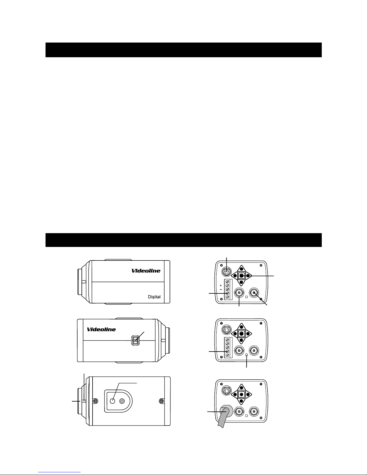
2. Descriptions
1/4"-20 UNC
MC-2620C/2620E
MC-2621C/2621E
MC-2622C/2622E
D.
B.
A
.
C.
J.
I.
PL VIDEO OUT MONITOR
COM PORT
DC
12V
NC
PL VIDEO OUT MONITOR
COM PORT
~AC24
DC12
NC
GND
PL
VIDEO OUT MONITOR90~250VAC
COM PORT
N.
G.
H.
M.
L.
K.

4
A. C mount lens adapter
If a CS mount lens (not included) is applied, C mount adapter ring should
be removed.
B. Back focus locking screw
Loosen this screw to adjust the back focal length to fit with different type
of lens.
C. Mounting bracket screw hole (1/4” – 20 UNC)
D. Auto iris lens connector (Mini Jack)
E. Video/DC drive AI lens selector
F. DC level adjuster
Adjustment may be required if a DC drive auto iris lens is used.
G. Video output terminal (BNC)
H. On-Screen Display control buttons
I. Monitor output / VBS or VS Gen-lock sync. input
This terminal on model MC-2620 & MC-2622 is a parallel video output for
on-site monitor connection. For model MC-2621, this terminal is for
VBS/VS Gen-lock synchronization signal input.
J. RS-232 COM Port
This port is for connection with CP-01 or RS-232 remote control facility.
K. Power supply LED indicator
L. AC power cord (MC-2622)
Poor quality power supply may result in inferior picture.
M. 24 VAC/12 VDC power input terminal (MC-2621)
This terminal is non-polarity.
N. 12 VDC power input terminal (MC-2620)
DC VIDEO
~AC24V
DC 12V
NC
DC
12V
NC
1
2
4
3
5
1
2
4
3
DC VIDEO
1
2
4
3
DC VIDEO
3. Lens connections
Lens for 1/3, 1/2, 2/3 or 1-inch CCD with a CS or C-mount can be used on
this camera. If the illumination remains stable
(e.g. indoors), you can choose
a lens with manual iris adjustment. The camera should be set at AES mode,
so that the shutter speed will be automatically adapted depending on the
illumination. If the illumination changes rapidly
, you should choose a lens
with automatic iris (AI) control to ensure optimum exposure of the picture.
Both Video and DC drive AI lens can be used on this camera.
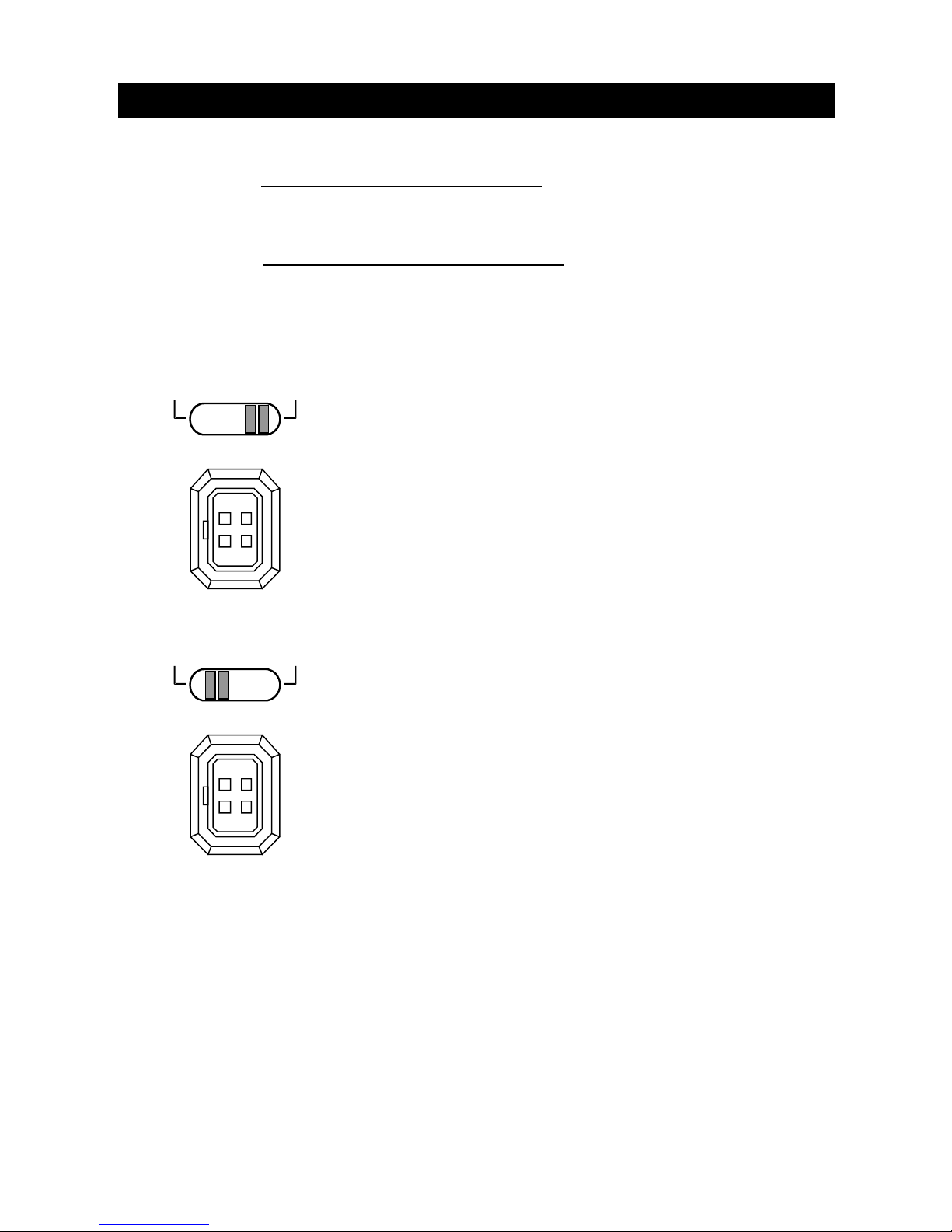
3.1 Video drive auto iris lens (with EE amp)
If a video drive auto iris lens is applied, ensure to
set the lens selector to “VIDEO” position.
Cable leads connection
1. Red ------Power supply
2. NC ------- Not used
3. White ----Video
4. Black ----Shielded (screen)
3.2 DC drive auto iris lens (without EE amp)
If a DC drive auto iris lens is applied, set the lens
selector to “DC” position.
Cable leads connection
1. Damping coil (-)
2. Damping coil (+)
3. Driving (+)
4. Driving (-)
To ensure correct lead connection, refer to the instruction of CCTV lens.
Incorrect connection may result in damage to the lens and camera.
3.3 Manual or fixed iris lens
The exposure control of this camera (electronic shutter control) is fully
automatic. It can compensate a change in the lighting level by a factor of
2000. If this is sufficient for the system, a lens with manually adjustable
or fixed iris can be used. When using this type of lens, the light control of
this camera must be set at AES via OSD control.

6
4. OSD Setup
All features and functions of this camera can be set or changed via its OSD
control. The OSD setup can be done via control buttons on the rear panel of
the camera, CP-01 (optional) remote control keypad or RS-232 remote
control facility from computer.
4.1 OSD Control Buttons
1. UP button
Press this button to move the cursor upward.
Use this button to select item.
2. LEFT button
Press this button to move the cursor left.
Use this button to change or adjust the
parameter of the selected item.
3. RIGHT button
Press this button to move the cursor right. Use this button to change or
adjust the parameter of the selected item.
4. DOWN button
Press this button to move the cursor downward. Use this button to select
item.
5. ENTER button
Press this button to access into OSD setup menu. If the selected item
has sub-menu, press this button to enter.
4.2 CP-01 Remote Controller
Connect the CP-01 OSD Remote Controller to the COM PORT of the camera,
All functions of this camera can be set via this remote controller. The
operation of CP-01 is same as the key buttons of camera.
4.3 RS-232 Computer connection
All functions of this camera can be remotely controlled by PC via RS-232
under Window 95/98.
1. Insert the attached disk into floppy and run OSD_0.EXE to extract all files
into hard disk.
2. Execute OSD_00.EXE. A virtue keypad icon will display on monitor.
3. Use the mouse to point the icons as like pressing the buttons.
For details of RS-232 connections, please enter the SETUP key on the
monitor.
OSD CONTROL
1
2
4
3
5
U
LER
D

7
5. Setup Menu
5.1 Main menu
Once access into OSD setup mode, the
main setup menu will appear on the
monitor. This menu contains 7 options for
setting all functions of the camera.
END - Exit from OSD setup mode.
Move the cursor to “END” at the
bottom line, then press “ENTER” button.
INIT - Reset all parameters to factory default value.
Move the cursor to “INIT” and press “ENTER” button. This operation will
erase all previous settings and return to factory default setting.
This operation should not be executed unless it is absolutely necessary.
DEMO – Demonstrate all functions of this camera.
Move the cursor to “DEMO” and press “ENTER” button to enter function
demo mode. Discontinue the power supply to stop the demo mode.
- Adjust the position of menu on the screen.
Move the cursor to “” and press “ENTER”. Press “UP” or “DOWN”
button to move the menu up or down on the screen.
UNLOCK – lock the setup menu.
Move the cursor to “UNLOCK” and press “ENTER”. Once the menu is
locked, the user must enter the following password to enter the menu.
UNLOCK PASSWORD : Press UP, DOWN, DOWN, RIGHT and then
ENTER buttons to unlock the menu.
Note: If no any button is pressed within 2 minutes under OSD setup mode, all
modified parameters will be stored automatically. The camera will return to
normal picture display mode.
SETUP MENU
CAMERA ID ON
LIGHT CNTL AES
WHITE BAL ATW
PICTURE VIDEO
DISPLAY MONOCH POS
OPD WINDOW
MISC
END INIT DEMO ↑ UNLOCK

8
6. CAMERA ID – Camera title setting
This camera provides the capability of setting its own identification title. Move
the cursor to “CAMERA ID” and press “ENTER” button to enter ID setting
sub-menu shows as below
6.1 Selecting character
Move the blinking cursor to the character. Press “ENTER” and the
selected character will display at the editing area according to the
selecting sequence. Repeat the procedure until all characters are
selected.
6.2 Editing camera title
Move the cursor to “” to edit any specific character at the editing
area. To erase a character or input a space between two characters,
move the cursor to the BLANK (between “z” and “,”) and press “ENTER"
button.
6.3 Setting title position
Move the cursor to “POSI” and press “ENTER”
button, then the selected camera title will display
on the screen. You can move the title to the
desired position by pressing “UP”, “DOWN”,
“RIGHT” and “LEFT” buttons.
Press “ENTER” button to fix the title position and return to the main
menu.
6.4 Setting title display
The brightness and fringe of title can also be adjusted. Move the cursor
to “BRI” to adjust the brightness of title. Press “ENTER” button to
increase the brightness. 5-step adjustments can be made and recycled
by pressing the “ENTER” button.
Move the cursor to “BLK” and press “ENTER” button to adjust the black
level of character outline. 5-step adjustments can be made and recycled
by pressing the “ENTER” button.
Character Area
CAMERA ID
0123456789:
ABCDEFGHIJK
LMNOPQRSTUV
WXYZabcdefg
hijklmnopqr
stuvwxyz ,.
□□□□□□□□□□□□□□□□□
RET POSI ← → BRI BLK
Blinking
Editing Area
Command Area
↑
← CAM 001 →
↓

9
7. LIGHT CNTL – Exposure mode setting
This camera provides 6 different exposure modes for different environments
and applications. Move the cursor to “LIGHT CNTL”, then press “ENTER”
button to enter its sub-menu.
Press “RIGHT” or “LEFT” button to select the desired exposure mode, press
“ENTER” button to enter the sub-menu of the selected mode.
The exposure mode appears in the following sequence;
AES AES LOW FLICKERLESS AUTO IRIS AUTO IRIS+SHUTTER
ME AES
7.1 AES mode
Once enter into the AES sub-menu, the
screen will shows as right. This sub-menu
contains 6 setting options for selection.
7.1.1 BLC (Back Light Compensation) setting (for all AE modes)
This setting controls the operation of BLC. Press “LEFT” or “RIGHT”
button to switch the BLC ON or OFF respectively. The back light
compensation of this camera is a combination of Histogram and
Central window weighted. Both of these two types of BLC are
adjustable via the sub-menu of BLC. To enter BLC sub-menu, move
the cursor at BLC and press “ENTER” button. BLC setup menu will
show on the screen for setting.
SETUP MENU
CAMERA ID ON
LIGHT CNTL AES
WHITE BAL ATW
PICTURE VIDEO
DISPLAY B/W POS
OPD WINDOW
EXT SYNC INT
END INIT DEMO ↑ UNLOCK
AES MENU
BLC ON
Av:Pk 8:4
AGCMAX 36 dB
RESPONSE 03
AGCMIN 01 dB
SHUTLIM 1/100000
RETURN
Press
ENTER to
sub menu
A
UTO EXPOSURE MODE:
A
ES mode: 1/50(1/60) to 1/100,000 sec. AGC 0-36 dB.
A
ES LOW mode: 1/120(1/100) to 100,000 sec. AGC 0-36dB.
FLICKERLESS mode: 1/120 sec. (CCIR); 1/100 sec.(EIA), AGC 0-36dB.
A
UTO IRIS mode: 1/50 sec. (CCIR), 1/60 sec. (EIA) AGC 0-36dB.
A
UTO IRIS+SHUTTER mode: 1/50(1/60) to 1/10,000 sec. AGC 0-36 dB.
AES MENU
BLC ON
Av:Pk 8:4
AGCMAX 36 dB
RESPONSE 03
AGCMIN 01 dB
SHUTLIM 1/100000
RETURN

10
HIST BLC – ON/OFF
The HIST (Histogram) BLC is ideal for
the subject that is slightly less
illuminated and moves around within
the screen. This intelligent BLC
categorize the scene into three different
parts (high-medium-low) according to the luminous intensity and
calculate the histogram of each part. The built-in microcomputer will
detect the contrast of whole scene and turn the BLC on or off
automatically.
Press the “LEFT” or “RIGHT” button to switch the HIST BLC on or off.
BLC LEVEL (for Histogram BLC)
The compensation level of histogram BLC can be adjusted from 0 to
255. Default value is 13. Increasing the value will enhance the
compensation level.
WINDOWS BLC – ON/OFF
The WINDOW BLC is ideal for the scene that main object always
stays at the center of the screen. With this BLC mode, compensation
level of the central window is weighted more than the corners of the
scene. This type of BLC helps camera to provide better picture of the
subject with strong back light.
WNDW 0
WNDW 2
CENTRAL
WNDW WNDW 3
WNDW 1
Size and location of the center window can be adjusted within the
225 grids of screen. (Refer OPD setting for more details)
BLC SETUP MENU
HIST BLC ON
BLC LEVEL 13
WINDOWS BLC OFF
WNDW 0 WEIGHT 01
WNDW 1 WEIGHT 01
WNDW 2 WEIGHT 03
WNDW 3 WEIGHT 03
RETURN

11
Windows weighing setting
The weighing of windows 0 to 3 can be individually set within a range
from 0 to 15. Weighing of central window is fixed at maximum value
15. Default values of other windows are listed as follow;
WNDW 0 WEIGHT 1
WNDW 1 WEIGHT 1
WNDW 2 WEIGHT 3
WNDW 3 WEIGHT 3
The combination of these two types of BLC delivers this camera better
picture even under severe environment. However, the BLC may be
insufficient under extremely strong back light condition.
7.1.2 Av : Pk setting (for all AE modes)
This option determines the method of photometric measurement,
while using DC servo Auto Iris lens. Av value means that the
electronic convergence is automatically adjusted according to the
average video signal level of the object. Pk value means that the
electronic convergence is automatically adjusted according to the
peak video signal level of the object.
The Av : Pk ratio represents the portion of two different methods.
Total 12 combinations (0:12, 1:11, 2:10, 3:9, 4:8, 5:7, 6:6, 7:5, 8:4,
9:3, 10:2, 11:1, 12:0) can be set. The default setting is 8:4.
7.1.3 AGCMAX setting (for all AE modes)
This option determines the maximum gain of AGC level. Range of
AGCMAX setting is from 0 to 36 dB. The default setting is 30 dB.
Under the AES mode, AGC is normally at minimum level (0 dB) and
camera exposure is virtually controlled by electronic iris of the
camera. If the exposure is still insufficient even the shutter speed has
been switched 1/50 (1/60) sec., then the AGC will operate to optimize
the camera exposure. On the contrary, AGC will reduce the gain first
if camera is over exposure. However, if the exposure is still excessive
even the AGC is reduced to minimum, then electronic iris will shorten
the exposure time to optimize the exposure.

12
7.1.4 RESPONSE setting (for all AE modes)
This option determines the response speed of automatic exposure
system. This setting is particularly useful if the camera is installed for
car park or traffic monitoring. Slower response time could help user
to see the object in the car or license plate at night time.
To set this option, move the cursor to “RESPONSE” position. Adjust
the value by pressing “LEFT” or “RIGHT” button. Different value
represent different response time. The bigger the value, the slower
the response time. Range of response time can be set from 0.5
second (01) to 15 seconds (255). The factory default value is 0.5
second for general application.
7.1.5 AGCMIN setting (for all AE modes)
The AGCMIN means the minimum AGC level applied on the video
picture under normal lighting condition. To ensure optimum picture,
this option is normally set at 0 dB (factory default value). The ACMIN
can be set from 0 to 20 dB according to the system requirement.
To set AGCMIN, move the cursor to AGCMIN position on the AES
sub-menu, press “LEFT” or “RIGHT” to adjust the value.
7.1.6 SHUTLIM setting (for AES mode only)
The electronic shutter speed (under AES mode) is from 1/50 (1/60) to
1/100,000 sec. But if the system requires higher quality picture or
lower sensor smear, the fastest shutter speed can be set to different
limit (1/500, 1/1000, 1/2000, 1/5000, 1/10000, 1/20000, 1/50000,
1/100000 sec.). Factory default value is 1/100,000 sec.
7.2 AES LOW mode
The AES LOW mode helps to reduce blurring picture under low light
condition. Under this mode, the shutter speed is set at 1/100 sec. to
1/100,000 sec. for CCIR system and 1/120 sec. to 1/100,000 sec. for EIA
system.
7.3 AUTO IRIS mode
If an auto iris lens is used, this mode should be chosen to produce
optimum picture. With this mode, the shutter speed is fixed at 1/50 sec.
(CCIR) and 1/60 sec. (EIA). The exposure is controlled by AGC and auto
iris lens.

13
7.4 AUTO IRIS+SHUTTER mode
This mode is similar with Auto Iris mode, only
the shutter speed is variable. With this mode,
the camera is able to catch a fast moving
object with higher shutter speed, yet still
produces a clear picture without sacrificing
the depth of field. The shutter speed varies from 1/50 (1/60) sec. to
1/10,000 sec.
7.5 ME (Manual Exposure) mode
The ME mode means the shutter is fixed at a
certain speed. After select the LIGHT CNTL at
ME, press “ENTER” button to access into ME
sub-menu. Different shutter speed and gain
can be set by pressing “UP” or “DOWN”.
Shutter speed: 1/50 (1/60), 1/100 (1/120), 1/250, 1/500, 1/1000, 1/2000,
1/5000, 1/10000 sec.
Gain: 0, 6, 12, 18 dB
8. PICTURE – Picture performance setting
This camera provide various video picture control functions for different
performance settings. Move cursor to “PICTURE” and select the “RIGHT” or
“LEFT” to select the options. Press “ENTER” button to access into the submenu of selected option. Setting options will appear in following sequence;
VIDEO APERTURE GAMMA VIDEO
8.1 VIDEO setting
This setting option allows user to set various
parameters of video signal. Changing these
parameters will virtually affect the performance and
video picture of the camera.
BRIGHT setting
This parameter controls the brightness of video signal. Press “LEFT” or
“RIGHT” button to change the value of brightness. To recall factory
default value, press “ENTER” button.
AUTO IRIS-SHUT MENU
BLC ON
Av:Pk 8:4
AGCMAX 30 dB
RESPONSE 03
AGCMIN 00 dB
SHUTSPEED 1/60
RETURN
ME MENU
SHUTTER 1/50 SEC
GAIN 0 dB
RETURN
VIDEO MENU
✸BRIGHT 90
PEDESTAL 7.5 IRE
RETURN

14
PEDESTAL setting
This parameter controls the pedestal level of video signal. Press “LEFT”
or “RIGHT” button to adjust the level.
While adjusting brightness and pedestal level, a monitor and waveform
scope might be needed for observation.
8.2 APERTURE setting
This options allows user to change the
aperture correction function. Changing this
option will get different kind of sharpness of
video picture.
AP GAIN L is for horizontal low frequency of aperture correction.
AP GAIN H is for horizontal high frequency of aperture correction.
V AP GAIN is for vertical aperture correction.
8.3 GAMMA setting
This option allows user to set various gamma
values for different video pictures. Move cursor
to “GAMMA ADJ” and set it ON to change the
both gamma and knee values of Y signal.
Set “Y GAMMA ADJ” OFF for Y gamma = 1
OFF1 : gamma=1 with no knee effect.
OFF2 : gamma=1 with knee on effect.
Value 00 01 02 03 04 05 06 07
Gamma 0.9 0.8 0.7 0.6 0.45 0.35 0.25 0.1
9. DISPLAY – Video display mode setting
This option allows user to change various video display modes (positive and
negative) for special application. The video display of this camera can be
changed in the following sequence;
MONOCH POS MONOCH NEG
GAMMA MENU
Y GAMMA ADJ ON
Y GAMMA 04
Y KNEE 00
RETURN
APERTURE MENU
AP GAIN L 02
AP GAIN H 02
V AP GAIN 10
RETURN

15
10. OPD WINDOW – Optical detection window adjustment
This option allows user to adjust the size of optical
detection window. Move cursor to this option and
press “ENTER” button to adjust position and size of
OPD window. After setting complete, press “ENTER”
button to return to previous menu.
While adjusting the size of window, only bottom and right frames will
move to enlarge the window.
11. MISC – miscellaneous setting
This menu provides miscellaneous settings of the
camera which include synchronization adjustment,
auto iris lens selection and iris window adjustment.
11. 1 Synchronization
The MC-2620 is internally synchronized, so this option shows only “INT” and
no adjustment is needed.
For line-lock synchronization models (MC-2621/2622), user can select “INT”
or “LINE LOCK” according to system requirement. If select “LINE LOCK”,
press “ENTER” button to enter EXT SYNC sub-menu. Press “LEFT” or
“RIGHT” button to change the value of V-phase locking.
11.2 AUTO IRIS LENS
This option provides user to set the type of Auto Iris lens used. Press “LEFT”
or “RIGHT” button to select the lens type (DC/VIDEO)
11.3 IRIS WINDOW
This option allows user to manually override the iris window size of AI lens if
necessary. Increasing the value will open the iris.
OPD WINDOW MENU
OPD WINDOW POSITION
OPD WINDOWS SIZE
RETURN
MISC MENU
EXT SYNC INT
AUTO IRIS DC LENS
IRIS WINDOW 17
RETURN

16
12. Technical Specifications
Image device...........................1/3” IT super high sensitivity Ex-view HAD CCD
Signal system..........................CCIR or EIA standard
Picture element .......................CCIR: 795(H) X 596(V), EIA: 811(H) X 508(V)
Scanning system ....................CCIR: 625 lines, EIA: 525 lines, 2:1 interlace
Sync. system...........................Internal (MC-2620) / Line lock (MC-2621/2622)
Horizontal resolution...............600 TV lines
Minimum illumination..............0.005 lux @ F1.2, 0 lux under infrared (IR) illumination .
Infrared wavelength ................800 ~ 1050 nm
Aperture correction .................2H and V aperture, gain adjustable
Camera title setip ....................Up to 20 characters
Gain......................................... Max. 36 dB, AGC off
S/N ratio ..................................Better than 50 dB
Auto. exposure system ...........5 modes selectable via OSD setup
AE CCD iris mode...................1/50 (CCIR), 1/60 (EIA) ~ 1/100,000 sec.
Flickerless mode.....................1/100 (EIA), 1/120 (CCIR)
AE AES low mode...................1/100 (CCIR), 1/120 (EIA) sec. ~ 1/100,000 sec.
AE auto iris mode....................1/50 (CCIR), 1/60 (EIA) sec.
Manual exposure system Shutter: 1/50(1/60), 1/120, 1/250, 1/500, 1/1,000, 1/2,000,
1/5,000, 1/10,000 sec.
Manual gain setting................. 0, 6, 12, 18 dB
Auto iris lens............................Accepts Video/DC servo lens
Gamma ...................................0.45 (on) / 1.0 (off)
Back light compensation ........ Auto Detect On/off, Histogram plus window weighted BLC.
Video output signal .................Composite: 1 V
p-p
, 75Ω load
Y/C output ...............................Y: 1.0 V
p-p
/ C: 0.286 V
p-p
, 75Ω load
Lens mount ............................. CS / C mount (with adapter ring)
Operation temperature ...........-10°C ~ 50°C (14°F ~ 122°F )
Power supply ..........................MC-2620: 12VDC,
MC-2621: 24VAC+12VDC ,
MC-2622: 90~250VAC
Power consumption................3.0W (MC-2620/2621), 3.6W (MC-2622)
Dimensions .............................60 X 53 X 122 mm (W x H x D)
Specifications are subject to change without prior notice.
MC-2620 I/M, Eng. 058-26200-000 2001-12 V2.0
 Loading...