

Page 1
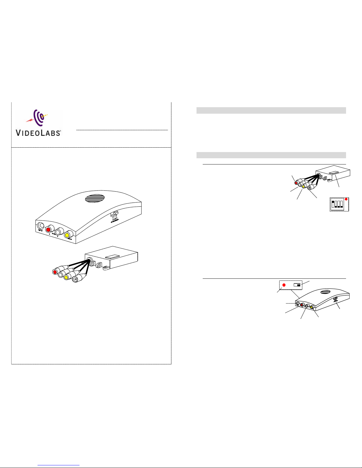
Channel
Selector
Video Connector
Left
(White)
Audio Connector
Right
(Red)
Audio
Connector
ON OFF
12V Power
Connector
Power Indicator
Power Switch
The VideoLabs’ Wireless Audio/Video System transmits live video
through the air instead of hard wires, allowing greater flexibility and
positioning of all VideoLabs cameras. Cameras can now be used in any
location without running a video cable from the camera to the monitor.
The wireless connection can extend over 700 feet.
In the Box:
The following items are included in the VideoLabs Wireless
Audio/Video System
• Transmitter
• Receiver
• 2 power supplies
• Y – power cable
• S-Video(M) to Composite(M) adapter cable (pigtail adapter)
Setup:
Transmitter
The camera outputs are
connected to the transmitter
inputs.
1. Connect the audio outputs
of the camera to the left
(white) and right (red)
audio inputs of the
transmitter. If there is only
one audio output on the
camera, connect it to either
audio input.
2. Use the included pigtail adapter to connect the s-video output to the Video
input of the transmitter. If your camera does not have a female s-video
jack, use the pigtail adaptor included with your camera, or call VideoLabs
customer service to buy a compact connection cable.
3. Lift the red plastic cover off the channel dip switches – put dip switch 1 in
the on position – put 2, 3, and 4 in the off position.
4. Replace the red plastic cover.
5. Plug the power supply into a wall outlet.
6. Plug the other end of the power supply into the female end of the Y power
cable.
7. Connect one of the Y cable male ends to the 12V power connector on the
transmitter, and the other to the 12V power connector on the camera.
Receiver
The receiver outputs are
connected to the monitor or
A/V equipment inputs.
1. Connect the left and
right audio outputs of
the receiver to the left
and right audio inputs
of the monitor. If there
is only one audio
output on the camera,
connect the same (left
or right) output that was used in the transmitter setup.
2. Connect the video output of the receiver to the video input of the monitor.
3. Set the channel selector to 1.
4. Plug the power supply into a wall outlet.
5. Plug the other end of the power supply into the 12V power connector.
6. Switch the power to the ON position.
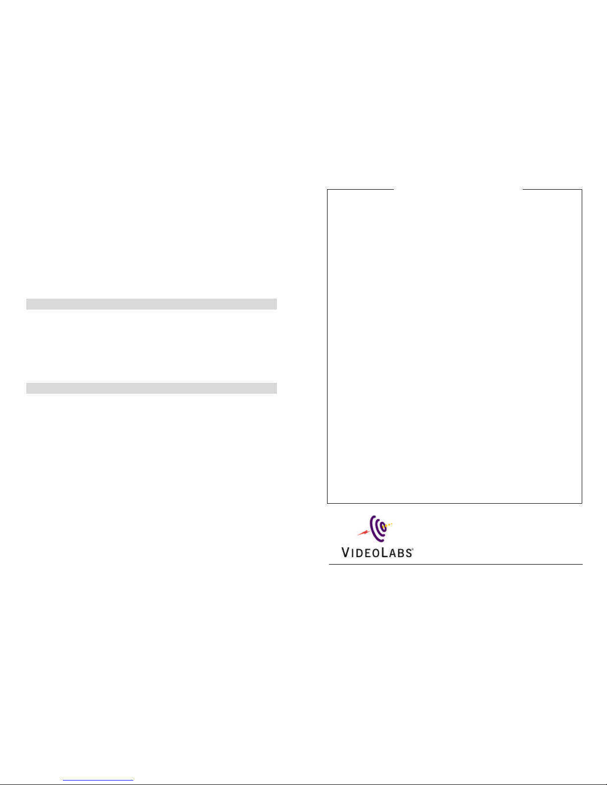
Channel Dip
Switches
Video
Connector
Left Audio
Connector
Right Audio
Connector
12V Power
Connector
ON
1 2 3 4
Wireless A/V
2.4 GHz
Wireless
Transmit
t
er and
R
eceiver System
Installation & User Guide
Page 2
There are four possible channels for the wireless A/V system. Any of the four can be
used, but the receiver must be on the same channel as the transmitter to receive the audio
and video. The channel selector is on the side of the receiver. The channel selector for
the transmitter is under the plastic cap. Only one of the switches should be in the ON
position at a time, the rest should be OFF. The switch that is in the ON position is the
selected channel.
The wireless transmission is omni directional, however best results may be obtained
when the transmitter and receiver are facing each other. Obstructions such as walls and
floors may decrease the maximum distance between the receiver and transmitter.
Interference and noise may be noticed when other transmitters are in use, such as cordless
phones, microwaves, aircraft radar, etc.
If noise is present, try relocating the devices or changing the channel on the transmitter
and receiver.
Care and Cleaning:
• Do not attempt to take the units apart. There are no user serviceable
components inside
• Keep the units away from food and liquid
• Do not operate or store units at temperatures above 1040 F (400 C) or below 32
0
F (00 C)
• Do not operate or store units in high humidity, dusty environments, inclement
weather, or under severe vibration
• Clean exterior of the units by wiping with a clean, damp cloth; do not use any
abrasive chemicals
FCC Regulations
The VideoLabs Wireless A/V device complies with Part 15 of the FCC Rules.
Operation is subject to the following two conditions: (1) this device may not cause
harmful interference, and (2) this device must accept any interference received, including
interference that may cause undesired operation.
This product transmits microwaves at a frequency of 2.4GHz. It is done in a fashion
which meets FCC requirements and limits its ability to interfere with normal radio,
television and communications frequencies. However, it has been designed in such a
fashion that other frequencies may have a tendency to interfere with this product and may
experience some distortion or noise from time to time as these signals may be received.
WARNING: Changes or modifications to this unit not expressly approved by the party
responsible for compliance could void the user's authority to operate the equipment.
NOTE: This equipment has been tested and found to comply with the limits for a Class B
digital device, pursuant to Part 15 of the FCC Rules. These limits are designed to provide
reasonable protection against harmful interference in a residential installation. This
equipment generates, uses, and can radiate radio frequency energy and, if not installed
and used in accordance with the instructions, may cause harmful interference to radio
communications. However, there is no guarantee that interference will not occur in a
particular installation. If this equipment does cause harmful interference to radio or
television reception, which can be determined by turning the equipment off and on, the
user is encouraged to try to correct the interference by one or more of the following
measures:
• Reorient or relocate the receiving antenna.
• Increase the separation between the equipment and receiver.
• Connect the equipment into an outlet on a circuit different from that to which
the receiver is connected.
• Consult the dealer or an experienced radio/TV technician for help.
Warranty Information on Hardware* - One (1) year limited warranty on all parts. VideoLabs
warrants this product against defects in materials and workmanship for a period of one (1) year from
the date of purchase. If VideoLabs receives notice of such defects during the warranty period,
VideoLabs will either, at its option, repair or replace products which prove to be defective.
Exclusions - The above warranty shall not apply to defects resulting from: improper or inadequate
maintenance by customer; customer-supplied software or interfacing; unauthorized modifications or
misuse; operation outside of the environmental specifications for the product; use of incorrect power
supply; or improper site operation and maintenance.
Obtaining Warranty Service - To obtain warranty service, product must be returned to a service
facility designated by VideoLabs. Customer shall prepay shipping charges for product(s) returned to
VideoLabs for warranty service and VideoLabs shall pay for return of the product(s) to customer.
However, customer shall pay all shipping charges, duties and taxes for product(s) returned to
VideoLabs from another country.
VideoLabs Customer Service - If the video equipment is still under warranty, VideoLabs will test,
repair or replace the product(s) without charge. If the video equipment is out of warranty, VideoLabs
will test, then repair the product(s) for the cost of parts and labor. Charges will be estimated by a
technician and confirmed by the customer prior to repair. All wireless components must be returned
to be tested as a complete unit. Repair time for all video equipment is a maximum of two (2)
business days from receiving to outbound shipping. VideoLabs will not accept responsibility for
shipment after the video equipment has left the premises.
VideoLabs Technical Support – VideoLabs technicians will determine and discuss with the
customer the criteria for repair costs and/or replacement. Contact VideoLabs Technical Support
through one of these sources: Phone: 866-384-3245 (U.S. only) or 763-542-0061; E-mail:
[email protected] or Web Site: www.videolabs.com.
RMA Number (Return Merchandise Authorization Number) - Before returning video equipment
for repair or replacement, request an RMA number from VideoLabs Technical Support. Provide the
technician with a return phone number or E-mail and a shipping address. Describe the product(s),
provide serial number(s), the reason for repair or return, and the date of purchase. Include your
assigned RMA number on all correspondence with VideoLabs. Write your assigned RMA number
on the outside of the box when you return the video equipment.
Voided Warranty - This warranty does not apply if the VideoLabs serial number has been removed
or if the product(s) has been disassembled or damaged through misuse, accident, modifications or
unauthorized repair.
Shipping and Handling - VideoLabs will not pay for inbound shipping, transportation or insurance
charges, or accept any responsibility for loss and/or damage from inbound transit. VideoLabs
requires that all overseas returns are shipped via UPS. VideoLabs will pay for outbound shipping,
transportation and insurance charges but will not assume responsibility for loss and/or damage by the
outbound freight carrier.
Products Not Under Warranty - Payment arrangements are required before outbound shipping for
all products that are out of warranty.
*VideoLabs manufactures its hardware products from parts and components that are new or
equivalent to new in accordance with industry-standard practices.
5960 Golden Hills Dr. ? Golden Valley, MN 55416-1040
763-542-0061 ? 800-467-7157 ? Fax 763-542-0069
www.videolabs.com
[email protected]
© 2001 E.mergent, Inc. Reproduction in whole or part without written permission is
prohibited. VideoLabs is a registered trademark of E.mergent, Inc. All rights reserved.
Specifications are subject to chance without notice.
Form Number 110501
Warranty Information
 Loading...