

Page 1

Videojet 2300
Series
Service Manual
P/N - 463001-21
Revision: AA, November 2017
Page 2

Copyright November 2017, Videojet Technologies Inc.(herein referred to as Videojet). All rights
reserved.
This document is the property of Videojet Technologies Inc. and contains confidential and proprietary
information owned by Videojet. Any unauthorized copying, use or disclosure of it without the prior
written permission of Videojet is strictly prohibited. CLARiTY
®
, CLARiSOFT® and CLARiNET® are
registered trademarks.
Videojet Technologies Inc.
1500 Mittel Boulevard Phone: 1-800-843-3610 Offices - USA: Atlanta, Chicago
Wood Dale, IL Fax: 1-800-582-1343 Int’l: Canada, France, Germany, Ireland, Japan, Spain,
60191-1073 USA Int’l Fax: 630-616-3629 Singapore, The Netherlands, and The United Kingdom
www.videojet.com Distributors Worldwide
Page 3

Compliance Information
Warning
For Customers in the U.S.A.
This device complies with Part 15 of the FCC Rules. Operation is subject to
the following two conditions:
1) This device may not cause harmful interference, and
2) This device must accept any interference received, including
interference that may cause undesired operation.
PERSONAL INJURY. Changes or modifications to this unit not
expressly approved by the party responsible for compliance could
void the user’s authority to operate the equipment.
This equipment has been tested and found to comply with the limits for a
Class A digital device, pursuant to Part 15 of the FCC Rules. These limits
are designed to provide responsible protection against harmful
interference when the equipment is operated in a commercial
environment. This equipment generates, uses, and can radiate radio
frequency energy and, if not installed and used in accordance with the
instruction manual, may cause harmful interference to radio
communications. Operation of this equipment in a residential area is likely
to cause harmful interference. In such cases, the users will be required to
correct the interference at their own expense.
Shielded cables must be used with this unit to ensure compliance with
Class A FCC limits.
The user may find the following booklet prepared by the Federal
Communications Commission helpful: How to Identify and Resolve
Radio-TV Interference Problems. This booklet is available from the U.S.
Government Printing Office, Washington, DC 20402, Stock No. 004-0000345-4.
This equipment has been tested and certified for compliance with U.S.
regulations regarding safety.
For Customers in Canada
This digital apparatus does not exceed the Class A limits for radio noise
emissions from digital apparatus set out in the Radio Interference
Regulations of the Canadian Department of Communications.
Rev AA i
Page 4

Videojet 2340, 2351 and 2361 Service Manual
This equipment has been tested and certified for compliance with
Canadian regulations regarding safety.
Pour la Clientèle du Canada
Le present appareil numerique n’emet pas de bruits radioelectriques
depassant les limites applicales aux appareils numerique de las class A
prescrites dans le Reglement sur le brouillage radioelectrique edicte par le
ministere des Communications du Canada.
Cet équipment est certifié CSA.
For Customers in the European Union
This equipment displays the CE mark to indicate conformance to the
following legislation:
EC EMC Directive 2014/30/EU
Essential health and safety requirements relating to electromagnetic compatibility.
EN 61000-6-4 Generic Emissions Standard for Heavy Industrial
Environments
EN 61000-3-2 Harmonic Current Fluctuations
EN 61000-3-3 Volt age Fluctuation and Flicker
EN 61000-6-2 Generic standards - Immunity for industrial
environments
EC Low Voltage Directive 2014/35/EU
Essential health and safety requirements relating to electrical equipment designed for use
within certain voltage limits.
EN 62368-1(IEC 62368-1)
Safety requirements for audio/video, information and communication technology
equipment.
ii
Rev AA
Page 5

EMC Directive
All machinery and ancillary equipment supplied by Videojet are certified
to EN and FCC standards which includes the necessary tests to ensure that
the equipment supplied meets the requirements of the Electromagnetic
Compatibility (EMC) Directive of the European Union and FCC rules
CFR47 relating to electromagnetic emissions.
Under no circumstances should any of the equipment or any of its
interconnecting cables supplied by Videojet be modified or altered in any
way as this may result in the equipment no longer complying with the
Directive and could leave the person or company making such
modifications liable to prosecution from the authorities.
It is also a requirement of the EMC Directive that any other items of
ancillary equipment that may be added to the products supplied by
Videojet (e.g. sensors, connection cables, junction boxes and so on) during
the normal course of an installation, should also be supplied and installed
in accordance with the EMC Directive. The person or company supplying
and installing these ancillary components or assemblies is responsible for
ensuring such compliance and in the event of non-compliance, would be
liable in the event of prosecution by the authorities.
Videojet 2340, 2351 and 2361 Service Manual
It is strongly recommended that all personnel involved in the installation
of equipment should be familiar with the EMC Directive and trained in
the correct installation methods required to ensure compliance of their
installation with the Directive.
The following guidelines intended to highlight the most important areas
of good installation practice when installing the Videojet equipment but
they are not intended to be a substitute for the installers own knowledge
of the Directive nor do they in any way assume responsibility for the
actions of the installer of the equipment.
Using Bought Out Parts for Use in an Equipment Installation
Before purchasing any components for use in an installation of the
Videojetequipment, you should check with the manufacturer that they
have been EMC tested to an EN standard which is relevant to your
equipment and are provided with EMC installation instructions e.g.:
•sensors and encoders
• programmable logic controllers (PLC)
• power supplies
• connection and junction boxes
If you buy components which have not been EMC tested you will have to
do the tests yourself.
Rev AA iii
Page 6

Videojet 2340, 2351 and 2361 Service Manual
Whilst there is no guarantee that an electrical installation made entirely
from EMC complying components will comply with the Directive, it is
more than likely that it will comply, provided the following basic
principles are followed.
Cabling
Cables which connect between items of equipment are a major cause of
radiated emissions and also act as antennae by which radiated
electromagnetic interference can enter an apparatus. It follows that cable
screening and separation is essential to achieve electromagnetic
compatibility. The following guidelines should be followed.
Cables in Enclosures
Cable to cable interference, by means of radiated emissions, can cause
problems within equipment enclosures. For instance, running an
unshielded data cable using a high frequency carrier next to an unshielded
analogue cable would cause carrier pick up in the analogue signal,
possibly to a level which would cause a malfunction of the equipment. It is
therefore necessary to group cables into one of the following four groups:
Group A Unshielded analogue cables
Unshielded cables for DC
Group B Shielded data cables
Shielded analogue cables
Unshielded cables for DC and AC < 60 V
Shielded cables for DC and AC < 280 V
Group C Unshielded cables for DC and AC < 60 V and < 280 V
Group D Unshielded cables for DC and AC > 280 V < 1 kV
Each cable group should be installed in separate cable ducts or cable
bundles in the enclosure.
For parallel runs of cable, there should be at least 100 mm between each
cable group.
Cable groups should only cross at right angles.
Where a shielded cable is used, care must be taken in the earthing of the
shield.
iv
When using a bought in component, the manufacturer's instructions
should be followed, but where no advice is available the guidelines below
can be used.
Rev AA
Page 7

Cables Outside of Enclosures
Figure : Best Practice
The following principles should be observed:
• Always use shielded analogue cables.
• Always shield digital signal cables, unless recommended otherwise
by the manufacturer or testing has shown that a shield is not required.
• Use twisted cables where possible to minimize ground loops; see best
practice example below.
Videojet 2340, 2351 and 2361 Service Manual
• Always run power, signal and returns together to minimize ground
loops.
• Install cables with voltages > 270 V in steel wire armoured cable or
metal conduit.
• Do not install signal cables directly parallel to power cables.
• Avoid using terminal lugs to extend cables.
• Very noisy or high frequency equipment will require cables with
copper braiding.
• Conduit if used should be metal.
• Flexible conduit must have glands which earth the metal liner.
• Steel trunking should not be relied upon for effective shielding.
Shield Termination
Where bought in equipment is being used, the manufacturer’s instructions
for the termination of shields should always be followed. However, where
no advice is given, the following guidelines can be followed:
• Earth the shield at both ends, unless doing so creates an undesirable
earth loop. If this is the case, earth at only one end, preferably at the
end which is closest to the central earthing point.
• Shielded cable should be connected to enclosures using glands which
gives 360° shield to metal contact.
Rev AA v
Page 8

Videojet 2340, 2351 and 2361 Service Manual
Figure : Cable Entry at Box Level
Communication Signals
Communication cables can be affected by radiated emissions to the point
where a malfunction can occur. For instance, if a RS232 communications
cable is run parallel to an unfiltered mains cable, radiated interference can
pass from the mains cable to the communications cable, possibly
corrupting the transmission.
Whether a communications link is a simple RS232 point to point link or a
more complex local area network (LAN), the manufacturer of the
communications equipment should provide instructions on how the
components should be installed and housed, to meet the requirements of
the EMC Directive. Inevitably, the actual installation will have different
cable lengths and numbers of devices from the configuration that the
manufacturer tested. However, due diligence can be shown by observing
the following points:
• Check that the equipment has been tested against relevant European
EMC standards.
• Use the recommended type of shielded cable.
• Use the recommended cable connectors, ensuring good shielding
continuity.
vi
Rev AA
Page 9

Contactors, Relays, Solenoid Valves etc
Unless suitably suppressed, contactors, relays, solenoid valves and other
devices which switch power voltages, will emit electromagnetic noise.
This is because when the operating coil (AC or DC) is switched off,
inductive voltage peaks of several thousand volts can occur. The effects of
these induced voltages may be:
• Arcing across the contacts of mechanical switching devices.
• Contact material damage of mechanical switching devices.
• Operational disturbances of electronic control devices.
• Destruction of electronic switching devices.
• Radio frequency interference due to high frequency electromagnetic
oscillations.
The same effects can also occur when using mechanical contacts to switch
on a load, due to contact bounce. These effects increase as the power of the
coil is increased.
Videojet 2340, 2351 and 2361 Service Manual
Earthing
However by wiring a suppressor in parallel with the load, the detrimental
effects can be significantly reduced. Ideally all loads should be
suppressed.
The positioning of each suppressor is important. Each suppressor should
be positioned as close as possible to its load, to prevent switch-off
oscillations in the current circuit wandering through the supply cables
causing potential emissions.
When designing the layout of an enclosure which contains any relays,
contactors, solenoids or other power switching devices, it is important that
they are kept separate from components switching signal voltages. This
may mean duplicating devices which switch both power and signal
voltages.
Correct earthing of the equipment can be the single most important
consideration in achieving compliance with the EMC Directive. The
equipment must use an incoming earth which is of good quality and good
earth integrity must be maintained between the components which make
up the equipment.
The quality of the incoming earth is generally the responsibility of the end
user, so it should be drawn to his attention in the installation manual that
this earth should be robust, of low impedance and noise free.
To achieve adequate earthing in an electrical apparatus the following
points should be followed:
Rev AA vii
Page 10

Videojet 2340, 2351 and 2361 Service Manual
• All electrically conducting parts should be connected to earth
potential either through their cases or with cable. For small parts
where this is prohibitively difficult, for example isolated motor shafts,
the part may be left unearthed.
• Where connection is made mechanically the joining surfaces must be
conducting (without paint, not anodised, etc.). The paint layer can be
broken using star washers, for example, but the surfaces must be anticorrosion treated with electrically conductive materials if corrosion is
likely. Avoid fasteners such as captive nuts, spring clasps and self
tapping screws. Plastic or anodised fasteners should not be used.
• Signal earths must not be shared with power returns. Single point
earthing is achieved if there is effectively a single earth, with all the
equipment connected to this point.
• Multiple point earthing is an alternative where single point earthing is
not feasible. In multiple point earthing, all equipment is connected to
an earth plane at the closest possible point. The earth plane might be
an equipment chassis or some other large conductive body should be
chosen for the earth plane.
• Earth loops are created when there is more than one earth conduction
path between the equipment and the incoming earth. Such earth loops
should be avoided.
• Avoid coiling earth cables.
• Dissimilar metals should be avoided for bonding purposes, where
water may be present. If dissimilar metals need to be used then coat
the bond with a water repellent material.
• Follow the installation recommendations given by the component
suppliers.
viii
Rev AA
Page 11

Videojet 2340, 2351 and 2361 Service Manual
Support and Training
Contact Information
If you have any questions or need assistance, contact Videojet
Technologies Inc.at 1-800-843-3610 (for all customers within the United
States). Outside the U.S., the customers must contact their Videojet
Technologies Inc.distributor or subsidiary for assistance.
Videojet Technologies Inc.
1500 Mittel Boulevard
Wood Dale, IL 60191-1073 U.S.A.
Phone: 1-800-843-3610
Fax: 1-800-582-1343
International Fax: 630-616-3629
Web: www.videojet.com
Service Program
About TotalSource
The TotalSource program is designed to protect your
investment in Videojet printers and deliver the lowest
total cost of ownership to your operations.
In addition to offering special pricing on Videojet high
quality consumables and parts, TotalSource also
provides comprehensive services and training at
attractive discounts - all designed to help you keep your lines up and
running.
• A complete array of customer services and offerings tailored to meet
your operational needs
• A program designed to maximize your equipment uptime, allowing
you to focus on your most important mission - your company’s
productivity
• A product and service program to support and deliver your ultimate
purchase: a high quality, reliable printed code on your finished
product.
Rev AA ix
Page 12

Videojet 2340, 2351 and 2361 Service Manual
Customer Training
If you wish to perform your own service and maintenance on the printer,
Videojet Technologies Inc.highly recommends you, to complete a
Customer Training Course on the printer.
Note: The manuals are intended to be supplements to (and not replacements for)
Videojet Technologies Inc. Customer Training.
For more information on Videojet Technologies Inc. Customer Training
Courses, call 1-800-843-3610 (within the United States only). Outside the
U.S., customer should contact a Videojet subsidiary office or their local
Videojetdistributor for more information.
x
Rev AA
Page 13

Table of Contents
Compliance Information
For Customers in the U.S.A.. . . . . . . . . . . . . . . . . . . . . . . . . . . . . . . . . . . . i
For Customers in Canada . . . . . . . . . . . . . . . . . . . . . . . . . . . . . . . . . . . . . . i
Pour la Clientèle du Canada . . . . . . . . . . . . . . . . . . . . . . . . . . . . . . . . . . . . ii
For Customers in the European Union. . . . . . . . . . . . . . . . . . . . . . . . . . . . ii
EMC Directive . . . . . . . . . . . . . . . . . . . . . . . . . . . . . . . . . . . . . . . . . . . . . iii
Using Bought Out Parts for Use in an Equipment Installation . . . . . . . iii
Cabling . . . . . . . . . . . . . . . . . . . . . . . . . . . . . . . . . . . . . . . . . . . . . . . . . . . iv
Cables in Enclosures . . . . . . . . . . . . . . . . . . . . . . . . . . . . . . . . . . . . . . . . . iv
Cables Outside of Enclosures . . . . . . . . . . . . . . . . . . . . . . . . . . . . . . . . . . . v
Shield Termination . . . . . . . . . . . . . . . . . . . . . . . . . . . . . . . . . . . . . . . . . . . v
Communication Signals . . . . . . . . . . . . . . . . . . . . . . . . . . . . . . . . . . . . . . vi
Contactors, Relays, Solenoid Valves etc . . . . . . . . . . . . . . . . . . . . . . . . . . vii
Earthing. . . . . . . . . . . . . . . . . . . . . . . . . . . . . . . . . . . . . . . . . . . . . . . . . . . vii
Support and Training
Contact Information . . . . . . . . . . . . . . . . . . . . . . . . . . . . . . . . . . . . . . . . . ix
Service Program . . . . . . . . . . . . . . . . . . . . . . . . . . . . . . . . . . . . . . . . . . . . ix
Customer Training . . . . . . . . . . . . . . . . . . . . . . . . . . . . . . . . . . . . . . . . . . . x
Chapter 1 — Introduction
Videojet 2300 Series Printer. . . . . . . . . . . . . . . . . . . . . . . . . . . . . . . . . . . 1–1
About this Manual . . . . . . . . . . . . . . . . . . . . . . . . . . . . . . . . . . . . . . . . . . 1–2
Related Publications . . . . . . . . . . . . . . . . . . . . . . . . . . . . . . . . . . . . . 1–2
Language Codes. . . . . . . . . . . . . . . . . . . . . . . . . . . . . . . . . . . . . . . . . 1–2
Content Presentation . . . . . . . . . . . . . . . . . . . . . . . . . . . . . . . . . . . . . . . . 1–3
The Word Printer . . . . . . . . . . . . . . . . . . . . . . . . . . . . . . . . . . . . . . . . 1–3
Positional References. . . . . . . . . . . . . . . . . . . . . . . . . . . . . . . . . . . . . 1–3
Units of Measurement. . . . . . . . . . . . . . . . . . . . . . . . . . . . . . . . . . . . 1–3
Safety Information . . . . . . . . . . . . . . . . . . . . . . . . . . . . . . . . . . . . . . . 1–3
Additional Notes . . . . . . . . . . . . . . . . . . . . . . . . . . . . . . . . . . . . . . . . 1–4
User Interface Terminology . . . . . . . . . . . . . . . . . . . . . . . . . . . . . . . 1–4
Abbreviations and Acronyms. . . . . . . . . . . . . . . . . . . . . . . . . . . . . . . . . 1–5
Chapters in the Manual . . . . . . . . . . . . . . . . . . . . . . . . . . . . . . . . . . . . . . 1–6
Chapter 2 — Safety
Introduction. . . . . . . . . . . . . . . . . . . . . . . . . . . . . . . . . . . . . . . . . . . . . . . . 2–2
Safety Conventions Used in the Manual. . . . . . . . . . . . . . . . . . . . . . . . 2–2
Warning Statements . . . . . . . . . . . . . . . . . . . . . . . . . . . . . . . . . . . . . 2–2
Caution Statements . . . . . . . . . . . . . . . . . . . . . . . . . . . . . . . . . . . . . . 2–3
Equipment Safety Guidelines . . . . . . . . . . . . . . . . . . . . . . . . . . . . . . . . . 2–3
Placement of the Printer . . . . . . . . . . . . . . . . . . . . . . . . . . . . . . . . . . . . . 2–4
Rev AA 1
Page 14

Videojet 2340, 2351 and 2361 Service Manual
Ink Safety Guidelines . . . . . . . . . . . . . . . . . . . . . . . . . . . . . . . . . . . . . . . .2–4
Safety Warnings for 2300 Series Printers. . . . . . . . . . . . . . . . . . . . . . . .2–7
Grounding and Bonding . . . . . . . . . . . . . . . . . . . . . . . . . . . . . . . . . .2–7
Electrical Power/Air Supply . . . . . . . . . . . . . . . . . . . . . . . . . . . . . . 2–7
Other Important Guidelines . . . . . . . . . . . . . . . . . . . . . . . . . . . . . . . . . .2–9
Medical Emergencies . . . . . . . . . . . . . . . . . . . . . . . . . . . . . . . . . . . . . . . .2–9
Emergencies Involving Printer Ink . . . . . . . . . . . . . . . . . . . . . . . . .2–9
Chapter 3 — Main Parts
About the Printer . . . . . . . . . . . . . . . . . . . . . . . . . . . . . . . . . . . . . . . . . . .3–1
Print Area. . . . . . . . . . . . . . . . . . . . . . . . . . . . . . . . . . . . . . . . . . . . . . .3–2
Main Parts . . . . . . . . . . . . . . . . . . . . . . . . . . . . . . . . . . . . . . . . . . . . . . . . .3–3
Chapter 4 — Installation
Unpack the Printer . . . . . . . . . . . . . . . . . . . . . . . . . . . . . . . . . . . . . . . . . . 4–1
How to Remove the Shipping Caps . . . . . . . . . . . . . . . . . . . . . . . . . . . .4–2
How to Remove the Shipping Plate . . . . . . . . . . . . . . . . . . . . . . . . . . . . 4–6
Videojet 2340 . . . . . . . . . . . . . . . . . . . . . . . . . . . . . . . . . . . . . . . . . . . .4–6
Videojet 2351 and 2361 . . . . . . . . . . . . . . . . . . . . . . . . . . . . . . . . . . .4–7
Installation Requirements . . . . . . . . . . . . . . . . . . . . . . . . . . . . . . . . . . . .4–8
Functional Requirements . . . . . . . . . . . . . . . . . . . . . . . . . . . . . . . . .4–8
Other Requirements. . . . . . . . . . . . . . . . . . . . . . . . . . . . . . . . . . . . . .4–9
Mounting Considerations . . . . . . . . . . . . . . . . . . . . . . . . . . . . . . . . . . .4–10
Mounting Bracket. . . . . . . . . . . . . . . . . . . . . . . . . . . . . . . . . . . . . . .4–12
How to Connect the Product Sensor . . . . . . . . . . . . . . . . . . . . . . . . . .4–13
Introduction. . . . . . . . . . . . . . . . . . . . . . . . . . . . . . . . . . . . . . . . . . . . 4–13
Type of Product Sensors . . . . . . . . . . . . . . . . . . . . . . . . . . . . . . . . . 4–14
Default Settings. . . . . . . . . . . . . . . . . . . . . . . . . . . . . . . . . . . . . . . . .4–14
How to Connect an Encoder . . . . . . . . . . . . . . . . . . . . . . . . . . . . . . . . . 4–16
How to Connect to the Host Machine Interlocks . . . . . . . . . . . . . . . . 4–17
How to Set the Correct Air Pressure . . . . . . . . . . . . . . . . . . . . . . . . . .4–18
How to Connect Data Communications . . . . . . . . . . . . . . . . . . . . . . .4–20
Port 1 . . . . . . . . . . . . . . . . . . . . . . . . . . . . . . . . . . . . . . . . . . . . . . . . .4–20
Port 2 . . . . . . . . . . . . . . . . . . . . . . . . . . . . . . . . . . . . . . . . . . . . . . . . .4–20
Stand-alone mode. . . . . . . . . . . . . . . . . . . . . . . . . . . . . . . . . . . . . . . 4–21
Network Mode . . . . . . . . . . . . . . . . . . . . . . . . . . . . . . . . . . . . . . . . .4–21
How to Set up Master/Slave Network . . . . . . . . . . . . . . . . . . . . . . . .4–21
Master/Slave Benefits . . . . . . . . . . . . . . . . . . . . . . . . . . . . . . . . . . .4–21
Master/Slave Applications . . . . . . . . . . . . . . . . . . . . . . . . . . . . . . .4–22
Printer Communications . . . . . . . . . . . . . . . . . . . . . . . . . . . . . . . . . 4–22
Physical Installation . . . . . . . . . . . . . . . . . . . . . . . . . . . . . . . . . . . . .4–23
Software Installation. . . . . . . . . . . . . . . . . . . . . . . . . . . . . . . . . . . . . . . .4–24
2
Rev AA
Page 15

CLARiTY Configuration Manager . . . . . . . . . . . . . . . . . . . . . . . . 4–24
How to Install CLARiTY Configuration Manager . . . . . . . . . . . 4–25
Chapter 5 — Printer Setup
Before you Turn On the Printer . . . . . . . . . . . . . . . . . . . . . . . . . . . . . . . 5–1
Turn On the Printer . . . . . . . . . . . . . . . . . . . . . . . . . . . . . . . . . . . . . . . . . 5–2
Insert New Ink Canister . . . . . . . . . . . . . . . . . . . . . . . . . . . . . . . . . . . . . 5–4
Videojet 2300 Priming Procedures. . . . . . . . . . . . . . . . . . . . . . . . . . . . . 5–4
How to Prime the 2340 Printer. . . . . . . . . . . . . . . . . . . . . . . . . . . . . 5–5
How to Prime Videojet 2351 and 2361 Printer. . . . . . . . . . . . . . . 5–12
How to Get High Quality Print . . . . . . . . . . . . . . . . . . . . . . . . . . . . . . 5–22
How to Connect PC to a 2300 Series Printer. . . . . . . . . . . . . . . . . . . . 5–22
CLARiTY Configuration Manager Parameters . . . . . . . . . . . . . . . . . 5–23
How to Select the Correct Printing Mode. . . . . . . . . . . . . . . . . . . . . . 5–29
Setting the Speed in Fixed Speed Mode . . . . . . . . . . . . . . . . . . . . 5–30
Setting the Speed in Encoder mode. . . . . . . . . . . . . . . . . . . . . . . . 5–32
How to Set the Correct Print Direction . . . . . . . . . . . . . . . . . . . . . . . . 5–33
How to Enable or Disable the Printhead. . . . . . . . . . . . . . . . . . . . . . . 5–34
How to Change the Self Cleaning Frequency of Operation. . . . . . . 5–35
How to Enable the Use Debris Pad . . . . . . . . . . . . . . . . . . . . . . . . . . . 5–37
How to Configure Master and Slave Units. . . . . . . . . . . . . . . . . . . . . 5–38
Basic Configuration . . . . . . . . . . . . . . . . . . . . . . . . . . . . . . . . . . . . . 5–38
Advanced Configuration . . . . . . . . . . . . . . . . . . . . . . . . . . . . . . . . 5–44
Using Master/Slave Mode . . . . . . . . . . . . . . . . . . . . . . . . . . . . . . . . . . 5–50
Group Job Select Mode . . . . . . . . . . . . . . . . . . . . . . . . . . . . . . . . . . 5–50
Group Control Mode. . . . . . . . . . . . . . . . . . . . . . . . . . . . . . . . . . . . 5–53
Videojet 2340, 2351 and 2361 Service Manual
Chapter 6 — CLARiTY Operator Interface
Introduction. . . . . . . . . . . . . . . . . . . . . . . . . . . . . . . . . . . . . . . . . . . . . . . . 6–1
Home Page of CLARiTY . . . . . . . . . . . . . . . . . . . . . . . . . . . . . . . . . . . . . 6–2
Screen Description . . . . . . . . . . . . . . . . . . . . . . . . . . . . . . . . . . . . . . . . . . 6–2
Icons . . . . . . . . . . . . . . . . . . . . . . . . . . . . . . . . . . . . . . . . . . . . . . . . . . . 6–2
Data Entry Pad . . . . . . . . . . . . . . . . . . . . . . . . . . . . . . . . . . . . . . . . . . . . . 6–5
Chapter 7 — Maintenance
Introduction. . . . . . . . . . . . . . . . . . . . . . . . . . . . . . . . . . . . . . . . . . . . . . . . 7–1
Routine Maintenance . . . . . . . . . . . . . . . . . . . . . . . . . . . . . . . . . . . . . . . . 7–2
Routine Cleaning . . . . . . . . . . . . . . . . . . . . . . . . . . . . . . . . . . . . . . . . 7–2
Scheduled Maintenance. . . . . . . . . . . . . . . . . . . . . . . . . . . . . . . . . . . . . . 7–3
Replacement Procedure . . . . . . . . . . . . . . . . . . . . . . . . . . . . . . . . . . 7–3
Shutdown Procedure . . . . . . . . . . . . . . . . . . . . . . . . . . . . . . . . . . . . . . . . 7–7
Rev AA 3
Page 16

Videojet 2340, 2351 and 2361 Service Manual
Normal Shutdown . . . . . . . . . . . . . . . . . . . . . . . . . . . . . . . . . . . . . . .7–7
Extended Shutdown. . . . . . . . . . . . . . . . . . . . . . . . . . . . . . . . . . . . . .7–7
Storage Shutdown . . . . . . . . . . . . . . . . . . . . . . . . . . . . . . . . . . . . . . .7–8
Draining the Printers . . . . . . . . . . . . . . . . . . . . . . . . . . . . . . . . . . . . . . . .7–9
Videojet 2340 . . . . . . . . . . . . . . . . . . . . . . . . . . . . . . . . . . . . . . . . . . . .7–9
Videojet 2351 and 2361 . . . . . . . . . . . . . . . . . . . . . . . . . . . . . . . . . .7–17
Preparation for Shipping . . . . . . . . . . . . . . . . . . . . . . . . . . . . . . . . . . . .7–26
Videojet 2351 and Videojet 2361 -
Preparing for Shipping (Wet - Distributor to End User) . . . . . .7–28
Chapter 8 — Troubleshooting
Fault and Warning Messages . . . . . . . . . . . . . . . . . . . . . . . . . . . . . . . . .8–2
Warnings . . . . . . . . . . . . . . . . . . . . . . . . . . . . . . . . . . . . . . . . . . . . . . . 8–2
Faults . . . . . . . . . . . . . . . . . . . . . . . . . . . . . . . . . . . . . . . . . . . . . . . . . .8–3
15 Way I/O Connector . . . . . . . . . . . . . . . . . . . . . . . . . . . . . . . . . . .8–4
Fault and Warning Messages . . . . . . . . . . . . . . . . . . . . . . . . . . . . . . 8–6
Troubleshooting the Faults . . . . . . . . . . . . . . . . . . . . . . . . . . . . . . . . . . 8–27
The Print is not in the Correct Position on the Box . . . . . . . . . . .8–27
The Printed Image is Back to Front or Upside Down . . . . . . . . .8–31
The Printer is Printing but is not Purging and Cleaning . . . . . . 8–32
The Print Quality is Poor. . . . . . . . . . . . . . . . . . . . . . . . . . . . . . . . . 8–34
The Printer is Error Free but not Printing an Image -
Batch Count not Incrementing . . . . . . . . . . . . . . . . . . . . . . . . . . . . 8–37
The Printer is Error Free but not Printing an Image -
Batch Count is Incrementing . . . . . . . . . . . . . . . . . . . . . . . . . . . . . 8–39
The Touchscreen Does Not React When Touched . . . . . . . . . . .8–40
The Printer Reports Ink Level Sensor Errors . . . . . . . . . . . . . . . . 8–41
Ink is Seeping Over The Printhead Front Plate or
Knife Edge . . . . . . . . . . . . . . . . . . . . . . . . . . . . . . . . . . . . . . . . . . . . . 8–42
Ink Leak Issues . . . . . . . . . . . . . . . . . . . . . . . . . . . . . . . . . . . . . . . . .8–44
Monoblock Vacuum Test Procedure . . . . . . . . . . . . . . . . . . . . . . . . . .8–45
Test Results and Solutions . . . . . . . . . . . . . . . . . . . . . . . . . . . . . . .8–45
Poor Quality or Missing Print at the Bottom of the
Printed Image . . . . . . . . . . . . . . . . . . . . . . . . . . . . . . . . . . . . . . . . . .8–46
Print is Missing From the Top of the Printed Image. . . . . . . . . .8–46
The LCD Does not Power Up . . . . . . . . . . . . . . . . . . . . . . . . . . . . . 8–48
The Back Light is On But LCD Image is Not Displayed. . . . . . . 8–49
CLARiTY Reports 'The Battery is Flat' . . . . . . . . . . . . . . . . . . . . . 8–50
The CLARiTY Screen of a Videojet Printer Reports
'Set Printhead Code' . . . . . . . . . . . . . . . . . . . . . . . . . . . . . . . . . . . . .8–50
4
Rev AA
Page 17

Chapter 9 — Illustrated Parts List
Air Valve Assembly . . . . . . . . . . . . . . . . . . . . . . . . . . . . . . . . . . . . . . . . . 9–4
Reservoir Air Filter Assembly . . . . . . . . . . . . . . . . . . . . . . . . . . . . . . . . 9–5
Can Present Microswitch Assembly . . . . . . . . . . . . . . . . . . . . . . . . . . . 9–6
Ink Shut Off Valve Assembly . . . . . . . . . . . . . . . . . . . . . . . . . . . . . . . . . 9–7
Standard LCD Display and Touchscreen . . . . . . . . . . . . . . . . . . . . . . . 9–8
Integral Product Sensor . . . . . . . . . . . . . . . . . . . . . . . . . . . . . . . . . . . . . . 9–9
Ink Reclaim Filter Assembly. . . . . . . . . . . . . . . . . . . . . . . . . . . . . . . . . 9–10
Vent Cap Assembly . . . . . . . . . . . . . . . . . . . . . . . . . . . . . . . . . . . . . . . . 9–11
Main Controller PCB . . . . . . . . . . . . . . . . . . . . . . . . . . . . . . . . . . . . . . . 9–12
Power Supply . . . . . . . . . . . . . . . . . . . . . . . . . . . . . . . . . . . . . . . . . . . . . 9–13
Power Switch. . . . . . . . . . . . . . . . . . . . . . . . . . . . . . . . . . . . . . . . . . . . . . 9–14
Spare Flash Card. . . . . . . . . . . . . . . . . . . . . . . . . . . . . . . . . . . . . . . . . . . 9–14
Air Regulator Filters. . . . . . . . . . . . . . . . . . . . . . . . . . . . . . . . . . . . . . . . 9–15
Vent Fitting . . . . . . . . . . . . . . . . . . . . . . . . . . . . . . . . . . . . . . . . . . . . . . . 9–15
Videojet 2300 Series Printer Part Numbers. . . . . . . . . . . . . . . . . . . . . 9–16
Accessories . . . . . . . . . . . . . . . . . . . . . . . . . . . . . . . . . . . . . . . . . . . . . . . 9–16
Kits . . . . . . . . . . . . . . . . . . . . . . . . . . . . . . . . . . . . . . . . . . . . . . . . . . . . . . 9–18
Tubing Kit . . . . . . . . . . . . . . . . . . . . . . . . . . . . . . . . . . . . . . . . . . . . . 9–18
Hardware Kit . . . . . . . . . . . . . . . . . . . . . . . . . . . . . . . . . . . . . . . . . . 9–18
Swab Cleaning Kit . . . . . . . . . . . . . . . . . . . . . . . . . . . . . . . . . . . . . . 9–19
Cleaning Kit . . . . . . . . . . . . . . . . . . . . . . . . . . . . . . . . . . . . . . . . . . . 9–19
Videojet 2340, 2351 and 2361 Service Manual
Appendix A — Frequently Asked Questions
How Does the Ink Delivery System Work? . . . . . . . . . . . . . . . . . . . . A–1
What Does the Ink Shut Off Valve Do?. . . . . . . . . . . . . . . . . . . . . . . . A–3
Videojet 2351 and Videojet 2361 . . . . . . . . . . . . . . . . . . . . . . . . . . A–3
Videojet 2340, Videojet 2351 and Videojet 2361 . . . . . . . . . . . . . A–3
When I Replace the PCB or Flashcard,
How Do I Restore The Original Parameters? . . . . . . . . . . . . . . . . . . . A–4
How to Clone the Printers. . . . . . . . . . . . . . . . . . . . . . . . . . . . . . . . . . . A–4
How is the Ink Level in the Reservoir Calculated? . . . . . . . . . . . . . . A–6
How Do I Clean the Printhead? . . . . . . . . . . . . . . . . . . . . . . . . . . . . . . A–9
Automatic Cleaning of the Printhead . . . . . . . . . . . . . . . . . . . . . A–9
How to Empty a Videojet 2361 Printhead for
Re-priming. . . . . . . . . . . . . . . . . . . . . . . . . . . . . . . . . . . . . . . . . . . . . . . . . . . . . . . . . . A–11
How to Set Up a Master/Slave Network? . . . . . . . . . . . . . . . . . . . . A–11
Glossary
Rev AA 5
Page 18

Introduction
This chapter contains the following topics:
• Videojet 2300 Series Printer
• About this Manual
• Content Presentation
• Abbreviations and Acronyms
• Chapters in the Manual
1
Videojet 2300 Series Printer
The 2300 Series printers are large character inkjet printers that print
accurate and high resolution text, alphanumeric codes, barcodes and
graphics. The user interface has quick and easy-to-use features.
The 2300 Series printers have an autopurge feature that can flush the
printhead nozzles before every print, at production line speeds. This
feature prevents:
• Operator intervention
• Production line/printing interruptions
•Ink wastage
This feature helps the printers to sustain good print quality across prints.
Rev AA Videojet 2300 Series Printer 1-1
Page 19

Videojet 2340, 2351 and 2361 Service Manual
About this Manual
The Videojet 2300 series Service Manual is written for the service
technicians. The service manual provides the procedures to install,
maintain, and troubleshoot the printer correctly.
Related Publications
The following manuals are available for reference:
• Videojet 2300 series Operator Manual (Part Number 463000).
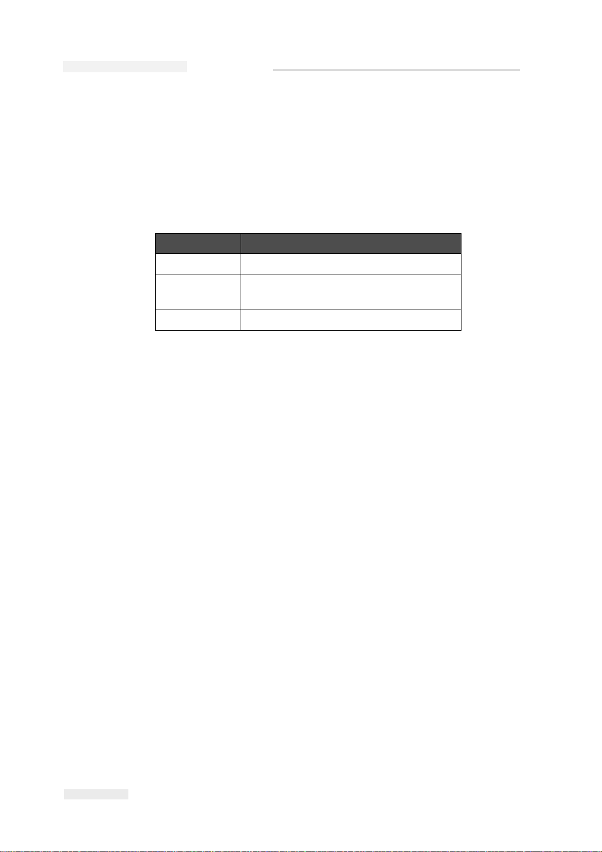
Language Codes
When you order these manuals, make sure to add the 2-digit language
code at the end of the part number. For example, the Dutch version of this
manual is part number 463000-09. The Table 1-1
that identify the translated versions of this manual.
lists the language codes
Code Language Availability (see
note)
01 English (US) * +
02 French *
03 German *
04 Spanish (Universal) *
05 Portuguese Brazilian *
06 Japanese *
07 Russian *
08 Italian *
09 Dutch *
10 Chinese (Simplified) *
11 Arabic *
15 Norwegian *
17 Swedish *
Table 1-1: List of Language Codes
1-2 About this Manual
18 Danish *
19 Greek *
21 English (UK) * +
Rev AA
Page 20

Code Language Availability (see
23 Polish *
24 Turkish *
26 Hungarian *
Table 1-1: List of Language Codes (Continued)
Note: The following symbols in the ‘Availability’ column indicates the following:
(*) - The symbol indicate the availability of Operator Manual
(+) - The symbol indicate the availability of Service Manual
For more information, consult your Videojet distributor or subsidiary.
Content Presentation
Videojet 2340, 2351 and 2361 Service Manual
note)
The manual contains different types of information like safety guidelines,
additional notes, User Interface (UI) concepts and so on. To help you
identify the different types of information, different writing styles that are
used in this manual. This section describes these writing styles.
The Word Printer
The word printer indicates the Videojet 2300 printer, from this point
forward, in this manual.
Positional References
Unless stated to the contrary, positions and directions such as left, right,
front, rear, to the right and to the left given with respect to the printer
when viewed from the front.
Units of Measurement
This manual uses metric units of measurement. The equivalent English
measures are included in parenthesis. For example, 240 mm (9.44 inches).
Safety Information
The safety information includes warning and caution statements.
Rev AA Content Presentation 1-3
Page 21

Videojet 2340, 2351 and 2361 Service Manual
Warning
Caution
Warnings
The warning statements indicate hazards or unsafe practices which may
result in severe personal injury or death.
For example:
The cleaning agent is poisonous if taken internally. Do not drink.
Seek medical attention immediately if ingested.
Caution
The caution statements indicate hazards or unsafe practices that can result
in damage to the equipment.
For example:
Do not fit or remove any connector on the printer when the power is
on, otherwise the printer may get damaged.
Additional Notes
Notes provide additional information about a particular topic.
For example:
Note: You can set the password protection for some functions to prevent any
access that is not authorized.
User Interface Terminology
All the elements of the User Interface (UI) are written in italics. For
example: The Stop button.
1-4 Content Presentation
Rev AA
Page 22

Abbreviations and Acronyms
Abbreviation Expansion
EAN European Article Number
EMC Electromagnetic compatibility
PC Personal Computer
PCB Printed Circuit Board
PNP Positive-Negative-Positive
USB Universal Serial Bus
Table 1-2: Abbreviations and Acronyms
Videojet 2340, 2351 and 2361 Service Manual
Rev AA Abbreviations and Acronyms 1-5
Page 23

Videojet 2340, 2351 and 2361 Service Manual
Chapters in the Manual
This manual is divided into 10 chapters. An introduction to the topics that
each chapter covers is shown in Table 1-3.
Chapter No. Chapter Description
1. Introduction Contains the information about this manual and
writing styles used in this manual.
2. Safety Contains the safety and hazard information
3. Main Parts Describes the main parts of the printer
4. Installation Describes the procedures to install the 2300
series printer and configure the CLARiTY
software.
5. Printer Setup Describes the setup procedures of the printer
before operation.
6.
7. Maintenance Contains the maintenance procedures of the
8. Troubleshooting Contains the troubleshooting procedures
9. Illustrated Parts List Contains the illustrated parts list and spare parts
10. Appendix A Contains the answers to frequently asked
CLARiTY
Interface
Operator
Describes the CLARiTY user Interface
printer.
list.
questions
Table 1-3: List of Chapters
1-6 Chapters in the Manual
Rev AA
Page 24

Safety
Caution
Warning
2
This chapter contains the following topics:
•Introduction
• Safety conventions used in this manual
• Equipment safety guidelines
• Placement of the printer
• Ink safety guidelines
• Safety Warnings for 2300 Series Printers
• Medical emergencies
EQUIPMENT DAMAGE. Read this chapter thoroughly before
attempting to install, operate, service, or maintain this equipment.
PERSONAL INJURY. The intended use of this printer is to print
information directly onto a product. Follow the installation and
operating instructions at all times. Only trained personnel should
carry out maintenance or repair. Use of this equipment for any other
purposes may lead to serious personal injury.
Rev AA 2-1
Page 25

Videojet 2340, 2351 and 2361 Service Manual
Warning
Introduction
The policy of Videojet Technologies Inc. is to manufacture non-contact
printing/coding systems and ink supplies that meet high standards of
performance and reliability. Therefore, we employ strict quality control
techniques to eliminate the potential for defects and hazards in our
products.
The safety guidelines provided in this chapter are intended to educate the
operator on all safety issues so that the operator can operate the printer
safely.
Safety Conventions Used in the Manual
Specific safety information is listed throughout this manual in the form of
Warning and Caution statements. Pay close attention to these statements
as they contain important information that help in avoiding potential
hazards to yourself or to the equipment.
Warning Statements
• Warning statements are used to indicate hazards or unsafe practices
that may result in personal injury or death.
• They have a triangular symbol with an exclamation mark to the
immediate left of the text.
• They are always preceded by the word “Warning”.
• They are always found before the step or information referring to the
hazard.
For example:
PERSONAL INJURY. The next step, “Cleaning the Printhead,” must
be performed by service or maintenance personnel. Qualified
personnel are those who have successfully completed the training
courses, have sufficient experience with the printer, and are aware of
the potential hazards to which they are exposed.
2-2 Introduction
Rev AA
Page 26

Caution Statements
Caution
Warning
Warning
• Caution statements are used to indicate hazards or unsafe practices
that can result in equipment or property damage.
• They have a triangular symbol with an exclamation mark to the
immediate left of the text.
• They are always preceded by the word “Caution”.
• They are always found before the step or information referring to the
hazard.
Example:
EQUIPMENT DAMAGE. Never turn off the printer by switching the
AC power switch to the Off (O) position. Before pressing the Off key,
allow the printer to complete the three and a half minute shutdown
sequence. Failure in following this procedure prevents the printer
from drawing the ink in the ink return line, back into the reservoir.
This may cause the ink to dry in the ink return line, resulting in
problems when you turn the printer on again.
Videojet 2340, 2351 and 2361 Service Manual
Equipment Safety Guidelines
This section contains important safety guidelines pertaining to the
operation and handling of the printer and associated equipment.
PERSONAL INJURY. While performing maintenance or repair
work, disconnect the mains supply unless it is absolutely necessary
to leave the supply on while carrying out adjustments.
PERSONAL INJURY. All electrical wiring and connections must
comply with applicable local codes. Consult the appropriate
regulatory agency for further information.
Rev AA Equipment Safety Guidelines 2-3
Page 27

Videojet 2340, 2351 and 2361 Service Manual
Warning
Warning
Warning
PERSONAL INJURY. Do not, under any circumstances, remove or
obstruct any warning, caution, or instruction labels present on the
printer.
Placement of the Printer
PERSONAL INJURY. Do not place the printer in a hazardous
location. Hazardous locations might create an explosion, leading to
personal injury.
Hazardous locations, as defined in the United States, are those areas that
may contain hazardous materials in a quantity sufficient to create an
explosion. These are defined in Article 500 of the National Electrical Code
ANSI/NFPA 70–1993.
Outside the United States, you must ensure compliance with all local
regulations regarding equipment placement in potentially hazardous
locations.
Ink Safety Guidelines
This section provides important safety guidelines pertaining to the use
and handling of inks. Read the appropriate MSDS for more information.
PERSONAL INJURY. Always observe the following safety
guidelines when using or handling inks.
For continued protection against possible fire hazard, use only
Videojet supplies with a flash point no lower than -22 C (-8 F) and
boiling point no lower than 56 C (133 F).
2-4 Placement of the Printer
Rev AA
Page 28

Videojet 2340, 2351 and 2361 Service Manual
Warning
Warning
Warning
Warning
Warning
PERSONAL INJURY. The printer ink is volatile and flammable. It
must be stored and handled according to local regulations. Work
only in areas with good ventilation.
PERSONAL INJURY. Do not smoke or use a naked flame in the
vicinity of the printer ink.
Immediately after use, remove any tissue or cloth that becomes
saturated with the ink. Dispose all such items in accordance with the
local regulations.
Only full bottles are recommended for use when replenishing ink;
partially filled bottles must be disposed in accordance with the local
regulations.
PERSONAL INJURY. Do not smoke when you are near the printer
or printhead. If the printer exhaust fumes are subjected to an ignition
source, it may result in an explosion or fire.
PERSONAL INJURY. Wear safety glasses with side shields (or
equivalent eye protection) when handling ink. If it splashes on your
eyes, flush your eyes with water for 15 minutes and consult a
physician immediately.
PERSONAL INJURY. Wear butyl rubber gloves when handling ink.
Avoid contact with skin and mucous membranes (nasal passage,
throat). Upon contact with skin, remove any contaminated clothing
and wash the area with soap and water. Consult a physician if
irritation persists.
Rev AA Ink Safety Guidelines 2-5
Page 29

Videojet 2340, 2351 and 2361 Service Manual
Warning
Warning
Warning
PERSONAL INJURY. Do not pour the ink into sinks, sewers, or
drains. Waste disposal must comply with local regulations. Contact
the appropriate regulatory agency for further information.
PERSONAL INJURY. Read and understand the Material Safety Data
Sheet (MSDS) before using the printer ink. An MSDS exists for each
type of ink. The appropriate sheet or sheets are supplied along with
the shipped product.
Ensure that you retain all MSDSs for future reference in case you
need to consult a physician regarding an ink-related accident.
Additional copies of MSDSs are available upon request, and can be
obtained by contacting the Videojet Customer Service Department at
1-800–843–3610. Outside the U.S., customers should contact a
subsidiary Videojet office or their local Videojet distributor.
PERSONAL INJURY. Certain inks are flammable and must be stored
appropriately. Storage must comply with local regulations. Contact
the appropriate regulatory agency for further information. The label
on the bottle or the MSDS indicates if a particular ink is flammable or
not.
2-6 Ink Safety Guidelines
Rev AA
Page 30

Videojet 2340, 2351 and 2361 Service Manual
Warning
Warning
Warning
Warning
Warning
Safety W arnings for 2300 Series Printers
Grounding and Bonding
PERSONAL INJURY. Always prevent static discharge from
occurring. Use proper Grounding and Bonding methods.
PERSONAL INJURY. Always bond conductive equipment together
with approved cables to maintain them at the same potential and
minimize static discharge. For example, printhead to metal service
tray.
Electrical Power/Air Supply
PERSONAL INJURY. Before opening or removing any printer
covers, ensure that the mains power is disconnected and compressed
air supplies are switched off.
PERSONAL INJURY. This equipment must be installed with a
locally positioned mains supply isolation device. This can be either a
plug and socket or a switch disconnected or circuit breaker in
accordance with IEC 60947-3 or IEC 60947-2.
PERSONAL INJURY. Always isolate equipment from the mains and
remove mains power connector to the printer before attempting any
maintenance or repair on any part of the product.
Rev AA Safety Warnings for 2300 Series Printers 2-7
Page 31

Videojet 2340, 2351 and 2361 Service Manual
Warning
Warning
Warning
Warning
PERSONAL INJURY. Before connecting compressed air supply to
Videojet 2340, 2351 and 2361, ensure that the air regulator is
switched OFF.
PERSONAL INJURY. Ensure that any cables from the printer are
secured to avoid chance of movement into walkways and becoming
a trip hazard.
PERSONAL INJURY. There will be sections of the Videojet 2340,
2351 and 2361 control board that will be permanently powered via
the on-board lithium battery - therefore it is essential that the board
should never be placed onto nor stored in or on any conductive
surface (including conductive, plastic bags etc.) as this would flatten
the battery and/or potentially result in battery overheating. The
battery cannot be replaced by the customer.
PERSONAL INJURY. Ensure that all external energy sources are
isolated from the printer before opening the outer casing. This
includes the mains power cable and I/O cable assembly (if used).
2-8 Safety Warnings for 2300 Series Printers
Rev AA
Page 32

Other Important Guidelines
Warning
Warning
Warning
Warning
PERSONAL INJURY. Do not point the printhead directly and in
close proximity to the eyes, unless the printer is switched off and
isolated from the mains and compressed air supplies.
PERSONAL INJURY. Read any warning or hazard information
supplied with the ink or consumable products. When using any
chemicals, always wear protective gloves and only use in wellventilated areas.
Videojet 2340, 2351 and 2361 Service Manual
PERSONAL INJURY. The Videojet 2340, 2351 and 2361 printer is
supplied with warning symbols for power supply and compressed
air. If any part of these symbols become damaged, worn or removed
they must be immediately replaced.
Medical Emergencies
This section provides important medical information in case of an
accident.
In the event of a medical emergency, contact a physician
immediately.
Emergencies Involving Printer Ink
If the incident involves the printer ink, carry the bottle and/or MSDS with
you to the physician’s office. These items contain important information
that the physician may require, to provide the precise medical treatment.
Rev AA Other Important Guidelines 2-9
Page 33

Main Parts
This chapter contains the following topics:
• About the printer
• Main Parts
About the Printer
The Videojet 2340, 2351, and 2361 printers are auto-purging ink jet
printers. The design of the printer enables the printer to print high
resolution text, barcodes and graphics. These printers are easy to use and
cost effective.
3
The 2300 series printers use the CLARiTY operator interface as a standard.
The interface is a part of the printer (that is you are not required to connect
the printers to an external Personal Computer (PC) for normal operation).
The icons in the interface provide easy navigation to the operator. The
Slave units do not have the interface.
An external PC is required only to configure the printer and download the
messages into the printer.
The auto-purging printhead makes sure that there is a consistent and high
quality code during the production period. This printhead does not use
more than the required amount of ink. The ink is supplied through non
pressurised, ink canisters that are installed in the canister chute which
make the printers clean and easy to use.
Rev AA About the Printer 3-1
Page 34

Videojet 2340, 2351 and 2361 Service Manual
Warning
Caution
Print Area
The print area for the 2300 series printers is shown in Table 3-1.
Printer Type Print Area
Videojet 2340
Videojet 2351
Videojet 2361
Table 3-1: Print Area
There will be sections of the Videojet control board that will be
permanently powered via the on-board Lithium battery. It is
essential that the board should never be placed onto nor stored in or
on any conductive surface (including conductive, plastic bags etc.) as
this would flatten the battery and/or potentially result in battery
overheating.
If the control board or printer is to be stored for any extended
duration, battery link LK5 can be removed and put onto only one of
the link posts until the board/printer is ready to be used. This
reduces battery drain. The battery has an expected five years life
span at normal ambient temperatures (0-40 C).
17 mm
53 mm
70 mm
x 2000 mm
x 2000 mm
x 2000 mm
3-2 About the Printer
Rev AA
Page 35

Main Parts
1. USB Port
2. I/O, Ethernet and Communications
Connectors
3. External Product Sensor (photoeye)
4. Air Inlet Connector
5. Mains Power Inlet
6. Printer Status LED
7. Power Switch
8. Ink Canister
9. CLARiTY Operator Interface
Figure 3-1: Printer Parts - Videojet 2340
1
2
3
2
4
5
8
6
7
Figure 3-2: Printer Parts - Videojet 2351 and 2361
1. USB Port
2. I/O, Ethernet and Communications
Connectors
3. Air Inlet Connector
4. External Product Sensor (photoeye)
5. Mains Power Inlet and Switch
6. Printer Status LED
7. Ink Canister
8. CLARiTY Operator Interface
Videojet 2340, 2351 and 2361 Service Manual
The following shows the main components of the printer with the
connection.
9
1
8
7
2
4
5
6
2
3
Rev AA Main Parts 3-3
Page 36

Videojet 2340, 2351 and 2361 Service Manual
1
2
3
Figure 3-3: Printhead - Videojet 2340
1. Internal Product Sensor
2. Printhead
3. Debris Collection Pad
Figure 3-4: Printhead - Videojet 2351 and 2361
1. Internal Product Sensor
2. Printhead
3. Debris Collection Pad
1
2
3
3-4 Main Parts
Rev AA
Page 37

Installation
This chapter contains the following topics:
• List of parts present in the printer package
• The procedure to remove the shipping caps and shipping plate
• Installation requirements
• Mounting considerations
• The procedure to connect print signals, encoder, host machine
interlocks, correct air pressure, data communications, and Master/
Slave Network
4
• The procedure to install the CLARiTY
Unpack the Printer
Unpack the printer, and make sure that all the parts listed in the Table 4-1
are present, and are not damaged.
Printer Type Contents
Videojet 2340
Printer
Videojet 2351
Printer
Videojet 2351
Slave Printer
CD-ROM including CLARiTY Configuration Manager
Air Regulator
QA Documentation and CE Certificate
CD-ROM including CLARiTY Configuration Manager
Air Regulator
QA documentation and CE certificate
CD-ROM including CLARiTY Configuration Manager
Air Regulator
QA documentation and CE certificate
Table 4-1: Printer Package List
Rev AA Unpack the Printer 4-1
Page 38

Videojet 2340, 2351 and 2361 Service Manual
Warning
Printer Type Contents
Videojet 2361
Printer
Videojet 2361
Slave Printer
CD-ROM including CLARiTY Configuration Manager
Air Regulator
QA documentation and CE certificate
CD-ROM including CLARiTY Configuration Manager
Air Regulator
QA documentation and CE certificate
Table 4-1: Printer Package List (Continued)
How to Remove the Shipping Caps
PERSONAL INJURY. Make sure that the mains power cable is
disconnected and the compressed air is switched off before opening
or removing printer covers.
4-2 How to Remove the Shipping Caps
Rev AA
Page 39

Videojet 2340, 2351 and 2361 Service Manual
1
1
1
Figure 4-1: Videojet 2340 Printer
1. Screws (x6)
1
Figure 4-2: Videojet 2351 and 2361Printer
1. Screws (x2)
Do the following tasks to remove the shipping caps:
1 Using a screwdriver remove the screws (six screws for Videojet 2340
and two screws for Videojet 2351 and 2361) that are attached to the
cover, and open the printer (see Figure 4-1 and Figure 4-2).
Rev AA How to Remove the Shipping Caps 4-3
Page 40

Videojet 2340, 2351 and 2361 Service Manual
Shipping Cap
Figure 4-3: Shipping Cap
2
1
Figure 4-4: Stainless Steel Fitting
1. Stainless Steel Fitting
2. Polyurethane Pipe
2 Remove the shipping cap from the ink reservoir (see Figure 4-3). Store
the cap at the indicated place for future use.
3 Remove the stainless steel fitting (Item 1, Figure 4-4) from the end of
the polyurethane pipe (Item 2).
4 Replace the shipping cap with the stainless steel fitting. Make sure
that the nylon washer is placed between the stainless steel fitting and
the Videojet ink reservoir.
Note: The stainless steel fitting has a vent hole on one edge.
4-4 How to Remove the Shipping Caps
Rev AA
Page 41

Videojet 2340, 2351 and 2361 Service Manual
2
1
Figure 4-5: Fit the Pipe
1. Knurled Flange Nut
2. Vent Hole
Figure 4-6: Vent Cap
5 Fit the polyurethane pipe onto the stainless steel fitting and hand
tighten the knurled flange nut (Item 1, Figure 4-5).
6 Refit the vent cap under the two retainers on ink reservoir.
Note: Make sure that the vent hole on the stainless steel fitting is in line with
material lining of vent cap. The material lining is present to capture ink mist
vented from reservoir spreading into the body of the printer.
Vent Cap
Rev AA How to Remove the Shipping Caps 4-5
Page 42

Videojet 2340, 2351 and 2361 Service Manual
Figure 4-7: Remove Shipping Plate
How to Remove the Shipping Plate
Videojet 2340
A new Videojet 2340 printer has a protective shipping plate covering the
nozzle array.
Do the following tasks to remove the shipping plate:
1 Remove the screws from the front and carefully remove the shipping
plate as shown in Figure 4-7.
Screws
2 Replace the screws into the printhead after removing the shipping
plate.
Store the shipping plate for the following reasons:
• To protect the printer when it is transported.
• To store the printer when it is unused for a long time.
Note: When you do not want to use the printer for some time, refit the clean
shipping plate carefully taking great care not to slide or wipe the print face.
4-6 How to Remove the Shipping Plate
Rev AA
Page 43

Videojet 2351 and 2361
Figure 4-8: Remove Protection Plate
Figure 4-9: Shipping Plate with Sealing
The shipping plate should be removed during priming for Videojet 2351
and 2361
Do the following tasks to remove the shipping plate:
1 Remove the two screws, that secure the shipping plate to the front of
the printhead (see Figure 4-8).
Videojet 2340, 2351 and 2361 Service Manual
Screws
2 Remove and retain the shipping plate along with orifice sealing plate
for future use.
Rev AA How to Remove the Shipping Plate 4-7
Page 44
Videojet 2340, 2351 and 2361 Service Manual
Installation Requirements
To install 2300 series printer successfully, the following inputs must be
available at the site of the printer installation:
Functional Requirements
The Table 4-2 provides the functional requirements of the 2300 series
printer.
Inputs Requirements
Power 100-240 VAC, 1~50/60Hz, 1.5-0.5A
Compressed
Air
Print Signal See “Print Signal” on page 4-8.
Table 4-2: Installation Requirements
Print Signal
Print signalling can be achieved through the following methods:
• A 24 VDC signal from a PNP sensor (available in diffuse sensor kit or
retro-reflective sensor kit that is supplied separately)
• The volt free print signal contacts, standard with every 2300 series
printer.
Note: All 2300 series printers contain an integral product sensor. However,
if the integral sensor is used, the printer cannot perform the printhead selfcleaning cycle.
It is highly recommended that a correctly screened, EMC Compliant,
remotely mounted retro-reflective product sensor is used wherever
possible.
6 Bar, dry, uncontaminated
Dust and dirt are the main causes of premature printhead failure. The
autopurge feature of the printer automatically cleans the printhead,
keeping it at its best operating condition. This feature also helps increase
the life of the printhead and ensures high quality printing.
Operating with a remotely mounted sensor will allow sufficient time for
the self-cleaning printhead cycle to activate between products as long as
the sensor is located in such a position that any product takes at least 0.4s
to travel from the print sensor to the print line. The distance will change
depending on the fastest speed of the line but the time is an absolute.
Sufficient spacing should be allowed so that there is at least 0.4s between
the products to allow automatic printhead cleaning.
Note: Ink will not flow from the canister, if the self-cleaning printhead cycle is
not operating.
4-8 Installation Requirements
Rev AA
Page 45

Other Requirements
Warning
In addition, a retro reflective sensor will reduce the possibility of false
print triggering, caused by product undulations, which can occasionally
occur with a diffused sensor. This is called the Print Gate function.
Sufficient space is required to mount the printer allowing easy access to
the ink canister and the CLARiTY touch screen.
If the product conveying equipment varies in speed, the Videojet encoder
kit will be required.
If barcodes are to be printed or high quality graphics are to be printed then
the use of an encoder to measure speed variations is critical for correct
operation.
It is essential that the Videojet 2300 printers are used with a fully
screened encoder. Failure to do so may result in equipment damage
and product malfunction. Any equipment damage resulting from
the use of incorrect or unscreened encoders will not be covered by
the equipment warranty.
Videojet 2340, 2351 and 2361 Service Manual
A suitable storage area for replacement ink canisters, dry with a
temperature between 2°C - 35ºC (35°F - 95°F) is required. Note that the ink
has a shelf life of 12 months.
If the printer is not being used, it should also be stored between 2°C - 35ºC
(35°F - 95°F) and if not used for more than two weeks, the unit should be
drained.
Rev AA Installation Requirements 4-9
Page 46

Videojet 2340, 2351 and 2361 Service Manual
Mounting Considerations
The 2300 series printer is shipped dry that is all the ink has been drained
from the system after final test.
In the shipped/dry state, the printer can be freely handled and positioned
in any orientation. However, extreme care should be taken around the
printhead area during handling.
The printer will require priming before operation. This process is
described in “Videojet 2300 Priming Procedures” on page 5-4.
The printhead is designed to operate only in a vertical orientation and
once filled with ink, care must be taken to ensure that it is kept in its
upright position.
The upright position presents a vertical printhead array, which is
designed to print onto vertical substrates, for example, side wall of a
cardboard case or tray.
The Table 4-3 provides the height of the vertical printhead array for 2300
series printers.
Printer Printhead Array
(Height)
Videojet 2340 17 mm
Videojet 2351 53 mm
Videojet 2361 70 mm
Table 4-3: Printhead Array Height
Mounting holes are provided on the printer sidewall, to attach to a
conveyor. To view the mounting holes of Videojet 2340 printer see
Figure 4-10 on page 4-11. To view the mounting holes of Videojet 2351 and
Videojet 2361 printer, see Figure 4-11 on page 4-11.
To view the Videojet 2340, Videojet 2351 and Videojet 2361 outline
dimensions, refer to Operator Manual.
4-10 Mounting Considerations
Rev AA
Page 47

Mounting Holes
Figure 4-10: Videojet 2340 Mounting Holes
Mounting Holes
Figure 4-11: Mounting Holes - Videojet 2351 and Videojet 2361
Videojet 2340, 2351 and 2361 Service Manual
Rev AA Mounting Considerations 4-11
Page 48

Videojet 2340, 2351 and 2361 Service Manual
Figure 4-12: Printer Mounting Bracket
Mounting Bracket
It is recommended to mount the printer to the side of the conveyor using
the printer bracket (Figure 4-12).
The mounting bracket for the 2300 series printers has been specifically
designed to allow quick and easy installation.
The features of the mounting bracket are:
• The mounting bracket enables the printer to be adjusted in the vertical
and horizontal planes, to allow a variety of products to be
accommodated.
• User friendly locking handles on the mounting bracket allow the
position of the printer to be quickly and easily adjusted during
production set up.
• The upright pole of the bracket may be angled up to +/- 20 degrees
from the vertical axis (Y axis in Figure 4-12) to accommodate inclined
conveyors. This is a rotation of the printer about the Z axis, in the X-Y
plane.
The printer must not be pitched up or down in the opposite direction (i.e.
a rotation about the X axis in the Y-Z plane)
4-12 Mounting Considerations
Rev AA
Page 49

Videojet 2340, 2351 and 2361 Service Manual
2
1
3
4
5
6
7
1. RS232 Communications Port
2. USB Port
3. External Product Sensor
(photoeye)
4. Air Inlet Connector
5. Mains Input Connector
6. I/O Connector
7. Network Port
Figure 4-13: Connections for Print Signal - Videojet 2340
2
1
3
4
5
6
7
1. RS232 Communications
Port
2. USB Port
3. Air Inlet Connector
4. External Product Sensor
(photoeye)
5. Mains Input Connector
6. I/O Connector
7. Network Port
Figure 4-14: Connections for Print Signal - Videojet 2351 and 2361
How to Connect the Product Sensor
Introduction
The Videojet 2300 series are supplied with an integral product sensor,
located on the front of the product, directly above the printhead (Figure 413 and Figure 4-14).
This sensor allows out of the box operation with no additional interfacing
required. However, it is highly recommended to use the external product
sensor to allow activation of the self-cleaning printhead cycle.
Rev AA How to Connect the Product Sensor 4-13
A connector for an external product sensor is located on the side of the
Videojet printer (see Figure 4-13).
Page 50

Videojet 2340, 2351 and 2361 Service Manual
15way Male
D-Type
SIG
PNP
Sensor
24 VDC
Figure 4-15: PNP Sensor (Print Sensor) Wiring
Type of Product Sensors
2300 series printers are configured to use any of the following product
sensors:
• Integral product sensor (recommended for print gating and
troubleshooting only).
• Optional retro-reflective sensor.
• Diffuse beam print sensor (standard).
• Alternatively, via volt-free or 24V contacts accessible with the optional
I/O cable.
Default Settings
The table provides the default settings of 2300 series printers.
Note: These settings are CLARiTY Configuration Manager settings and cannot
be set at the CLARiTY touch screen.
Printers Sensor Type
Videojet 2340 External
Videojet 2351 External
Videojet 2361 External
Table 4-4: Default
As default the setting for initializing the print cycle is Positive Edge
(leading edge of the product) triggering.
Figure 4-15 and Figure 4-16 on page 4-15 show the connections required
for 'volt-free' or 24 V operation utilizing the optional I/O cable.
4-14 How to Connect the Product Sensor
Rev AA
Page 51

Videojet 2340, 2351 and 2361 Service Manual
Figure 4-16: Volt-free Contact Wiring
15way Male
D-Type
SIG
Print Signal
Relay Contact
24VDC
1
2
3
4
1. 10-30 VDC
2. No connection
3. 0V
4. Normally Open Output
Figure 4-17: Remote Product Sensor Connector
In addition, the 15-way D-Type (male) connector, located on the side of
the Videojet printer, is also used for I/O connectivity, e.g. warning and
fault outputs, encoder, line selection.
The Remote Product Sensor connector, located on the side of the Videojet
printer. See Figure 4-17 for the following connections:
• 10-30 VDC
• No connection
•0 V
• Normally Open Output
Rev AA How to Connect the Product Sensor 4-15
Page 52

Videojet 2340, 2351 and 2361 Service Manual
Encoder
+24 V
Phase ASignal
Phase-B
Signal
0V
Figure 4-18: Encoder Wiring
How to Connect an Encoder
Encoders are used to track the speed of the conveyor and must be
connected via the 15 way D-type I/O connector mounted on the side of
the Videojet printer (see Figure 4-13 on page 4-13).
An encoder kit, is supplied complete with an I/O cable that connects
directly into the 15 way D-type connector, located on the side of the
Videojet printer.
In addition, the 15-way-D-Type (male) connector, located on the side of
the printer is also used for I/O connectivity, for example, warning and
fault outputs, encoder, line connection.
Note: The encoder settings are CLARiTY Configuration Manager parameters
and can not be set at the CLARiTY touch screen.
Figure 4-18 shows the 15 way D-Type pin connections.
4-16 How to Connect an Encoder
Rev AA
Page 53

Videojet 2340, 2351 and 2361 Service Manual
How to Connect to the Host Machine Interlocks
The 15-way D-type connector, located on the side of the 2300 series
printers (see Figure 4-13 on page 4-13) also has connections for a variety of
useful interlock and annunciation signals for use with the host packaging
machine or conveying system.
Note: The power (current) supplied from the Videojet printer is very low,
100mA Maximum. Therefore, the internal power supply should not be used for
powering indicator lamps (Fault, Warning, and Print) and a separate power
supply should be used to provide power.
Using CLARiTY Configuration Manager the outputs can be configured to
provide additional functionality in order to help integration with outside
systems.
Table 4-5 summarizes these inputs and outputs
Pin Purpose
1 24V DC Supply
2 Print (PNP)
30V DC
4 Line Select 0 (IN)
5 Line Select 1 (IN)
6 Line Select 2 (IN)
7 Fault Out (COM)
8 Fault Out (N/O) Output 1
9 Warning Outp ut (PNP) Output 2
10 Spare Output (PNP) Output 3
11 Line - Strobe (IN)
12 0V DC
13 Line Select 3 /External Print Gating Sensor (IN)
14 Encoder Channel B (IN)
15 Encoder Channel A (IN)
Table 4-5: Input and Output Pins
Note: The fault contacts (7, 8) change state as the printer enters and exits a
fault condition.
Rev AA How to Connect to the Host Machine Interlocks 4-17
Page 54

Videojet 2340, 2351 and 2361 Service Manual
3
2
1
Figure 4-19: Air Regulator
1. Videojet 2340 2.5 Bar
2. Videojet 2351/Videojet 2361 4.5 Bar
3. Control Knob
How to Set the Correct Air Pressure
Note: Before connecting compressed air supply to the 2300 series printer, ensure
the air regulator control knob has been turned off.
The air regulator (see Figure 4-19) should be mounted as close to the
printer as possible and in a position where the control knob and pressure
gauge are easily accessible.
Note: Air pressure can be viewed on the controller diagnostics (on printer
touchscreen, navigate to Tools > Diagnostics > Printhead > Inputs > Pressure
Sensor).
Connect dry, uncontaminated compressed air to the 6-mm connector of
the air regulator.
A second air line should be connected between the remaining 6-mm 'Air
Out' push fitting on the air regulator and the 6-mm Air In push fitting
located on the side of the Videojet printer.
4-18 How to Set the Correct Air Pressure
Rev AA
Page 55

Videojet 2340, 2351 and 2361 Service Manual
Warning
Turning the air regulator control knob clockwise will increase the air
pressure to the Videojet printer.
Note: The air pressure should be set in accordance to the printer model as shown
in Figure 4-19 on page 4-18 and Table 4-6.
Operating outside the recommended air pressure may cause
damage to the printer.
Make sure to use one air regulator per printhead. If you connect a
regulator between printheads, this will result in insufficient air supply if
both printheads purge/print at the same time. Low air pressure will cause
multiple problems including insufficient vacuum to reclaim the ink.
The table provides the recommended air pressure for 2300 series printers.
Printers Air Pressure
Videojet 2340 2.5 bar
Videojet 2351 4.5 bar
Videojet 2361 4.5 bar
Table 4-6: Recommended Air Pressure
Moisture filters located in the air regulator bowls should be replaced on a
regular basis, to ensure air to the Videojet printer remains dry and free
from contamination.
Rev AA How to Set the Correct Air Pressure 4-19
Page 56

Videojet 2340, 2351 and 2361 Service Manual
How to Connect Data Communications
Communications ports are provided with every 2300 series printers:
RS232 serial communications port x 2 (9-way male D-type connector,
located on the side of the Videojet 2351 and 2361 printer).
Note: Videojet 2340 has only one RS232 Serial Communications Port (Port 1).
Port 1
Pin Connection
1 Data Carrier Detect (DCD)
2 Receive Data (Rx)
3 Transmit Data (Tx)
4 Data Terminal Ready (DTR)
5 G round
Port 2
6 Data Set Ready (DSR)
7 Request To Send (RTS)
8Clear To Send (CTS)
9 Ring Indicator (RI)
Table 4-7: Pins of Port1
Pin Connection
2 Receive Data (Rx)
3 Transmit Data (Tx)
5Ground
Table 4-8: Pins of Port 2
Ethernet 10baseT/100baseTX high speed network port (RJ45 connector,
located on the side of the Videojet).
Videojet is primarily designed to communicate with CLARICOM
standard Package Coding Management Systems, such as CLARiSOFT
Image Design Software.
CLARiTY operating system can be configured to work in one of two
modes:
•Stand-alone mode
•Network mode
4-20 How to Connect Data Communications
Rev AA
Page 57

Stand-alone mode
Download to CLARiTY using a standard PC null-modem cable (twisted 9way D-type, female to female) connected between PC COM1 port and
CLARiTY RS232 port of the 2300 series printer or by Ethernet connection.
Network Mode
1 Create images on a PC using CLARiSOFT
2 Download to CLARiTY using Ethernet TCP/IP network and
CLARiNET network software.
3 Images (Jobs) can be requested from the CLARiTY touch screen or can
be selected and downloaded from any networked PC workstation that
is running CLARiNET.
Videojet 2340, 2351 and 2361 Service Manual
How to Set up Master/Slave Network
Master/Slave Benefits
Videojet Master/Slave capability is an enhancement to the Videojet
product range that allows you to control up to four Videojet printers from
a single CLARiTY operator interface.
A mixture of Videojet 2340, Videojet 2351 or Videojet 2361 printers can be
used in Master/Slave network, resulting in:
• An easier to use coding system - simpler setup of multiple printers
• Reduced printer setup time - a single point of setup
• A reduction in setup mistakes from human error - only one entry of
data rather than several
• A lower cost coding solution when multiple printers are required to
fulfill a coding application through the use of the new Videojet Slave
printer without LCD.
• All achieved without an additional controller or PC on the production
line.
Rev AA How to Set up Master/Slave Network 4-21
Page 58

Videojet 2340, 2351 and 2361 Service Manual
Master/Slave Applications
Master/Slave applications are typically used when:
• Coding more than one side of a box is required
• When two or more printheads are required to code onto the same side
of the box
• When control for multiple printers is required from a single location
In addition Master/Slave networks can create a very cost effective
solution where the print area required is higher than that of a single
printhead.
Examples: Videojet 2361 printhead (70 mm) + Videojet 2340 printhead
(17 mm) = Print height of 87 mm, both printers controlled from a single
CLARiTY screen
Or
Videojet 2361 printhead (70 mm) + Videojet 2351 head (53 mm) = Print
height of 123 mm, both printers controlled from a single CLARiTY screen
Or
Videojet 2361 printhead (70 mm) + Videojet 2361 head (70 mm) = Print
height of 140 mm, both printers controlled from a single CLARiTY screen
Master/Slave Terminology
Level 1: Group Job Select, allows connection of up to four standard 2300
series printers (with LCD's), with Job selection available only from the
printer configured as the Master. This mode greatly reduces potential
Operator errors when you enter variable data.
All other functions are performed at each local printer's LCD panel.
Level 2: Group Control, allows connection of one standard Videojet (with
LCD) acting as the Master, to up to three Videojet Slave (with or without
LCD) printers.
All Job selection, Setup, Diagnostics and Error reporting are performed at
the Master printer only.
Printer Communications
Initially, the printer will be configured through CLARiTY Configuration
Manager using RS232 connectivity. The Master/Slave group can be
configured through RS232 or Ethernet connectivity.
4-22 How to Set up Master/Slave Network
Rev AA
Page 59

Physical Installation
Figure 4-20: Connection Box
When only two Videojet printers (one Master, one Slave) are required and
there is no requirement to connect the Master/Slave group to an external
network, a two printer interconnection cable may be used to connect
directly between the Ethernet ports of the two printers.
All other cables (e.g. I/O cable) must be connected as for standalone
printers.
Where more than two printers are to be connected together or connection
to a network is required, the two Printer Connection Box or 3-4 Printer
Connection Box complete with Ethernet patch cables is required.
The Connection Box allows up to four Videojet printers (one Master and
three Slaves) to be connected together, allowing them to share common
encoder and print signals as well as providing Ethernet connectivity via
the integral network switch (hub).
In addition, the connection box also allows the group of printers to be
connected to a wider Ethernet network.
Videojet 2340, 2351 and 2361 Service Manual
Figure 4-20 shows a two printer Connection Box, showing the five port
connections for the network switch, integral I/O cables (2 off) and encoder
lead.
Rev AA How to Set up Master/Slave Network 4-23
Page 60

Videojet 2340, 2351 and 2361 Service Manual
Figure 4-21: CLARiTY Configuration Manager Screen
Software Installation
CLARiTY Configuration Manager
As coding and labelling equipment becomes increasingly versatile for a
wider range of applications, the number of variable parameters within a
printer can become very large.
Although printers are pre-programmed with so-called Default Values, as
the breadth of applications increase, the likelihood of the Defaults being
ideal for an application reduces. This can give rise to a large and
cumbersome menu tree of options for users to contend with.
The CLARiTY Configuration Manager aims to remove this problem,
leaving the printer with a small and manageable number of operating
variables, whilst maintaining the application flexibility of the machine.
Figure 4-21, shows a typical CLARiTY Configuration Manager screen.
Most printer variables are set at the point of installation. These variables
are set to tailor the printer to the application.
In the majority of cases, once set, these variables only need to be changed
if the application for the printer changes.
4-24 Software Installation
Rev AA
Page 61

Videojet 2340, 2351 and 2361 Service Manual
The CLARiTY Configuration Manager is a user-friendly PC software
program, which provides the following basic features:
• Complete set of printer variables
• Save/Retrieve a set of variable values to a PC file for later/repeat
use, or for taking backup or restoring of printer setup parameters.
• Download a set of variable parameters to the printer’s CLARiTY
control system for non-volatile (permanent) memory storage in the
printer
• Upload set of variable parameters from the printer, for review/
compare/modification
As a result, the 2300 series printer only retains a small number of
operating variables for the user to change.
In addition to making the CLARiTY Operating system less complicated
and more user friendly, an increased level of printer system security is
also added, as configuration variables can only be accessed from a
connected PC.
If a Videojet printer operates in stand-alone mode (i.e. not networked), the
PC should be linked for the period of uploading and downloading of the
configuration variables only. The PC should then be removed.
In a networked environment, system administrators have the ability to
directly access the printer, whilst Line Operators can access operating
variables on the CLARiTY operating system only.
How to Install CLARiTY Configuration Manager
Do the following tasks to install CLARiTY Configuration Manager:
1 Insert the CD-ROM with the CLARiTY Configuration Manager. The
installation routine will automatically start.
2 Follow the on-screen instructions.
Note: If auto run facility is disabled in your PC, the installation routine will
not start automatically.
3 Click Start, followed by Run and then type into the dialog box -
D:\setup.exe followed by OK
Note: D: is the drive letter of the PCs CD-ROM drive. If your CD drive is
different, substitute the letter D with the appropriate drive letter.
Rev AA Software Installation 4-25
Page 62

Printer Setup
This chapter describes the following:
• Turn on 2300 series Printer
• The priming procedures of 2340, 2351, and 2361 printers
• How to Get High Quality Print
• CLARiTY Configuration Manager Setup
• Using Master/Slave Mode
5
Before you Turn On the Printer
The following checks must be made before you turn on the 2300 series
printer:
1 The printer is mounted in its working position.
Note: Mount the printer level front to back and no greater than 20 degrees
from side to side.
2 The printer is connected to the main power supply.
3 The printer is connected to the compressed air supply.
4 The air regulator is turned on and set to:
• 2.5 bar for the Videojet 2340
• 4.5 bar for the Videojet 2351
• 4.5 bar for the Videojet 2361
5 The internal ink reservoir shipping cap is removed and replaced with
the air pipe and stainless steel fitting.
6 The vent cap is correctly fitted and aligned.
7 The printhead shipping plate is removed.
Rev AA Before you Turn On the Printer 5-1
Page 63

Videojet 2340, 2351 and 2361 Service Manual
Power Switch
Figure 5-1: Power Switch
Figure 5-2: CLARiTY Home Page
Turn On the Printer
Do the following tasks to turn on the 2300 Series Printer:
1 Press the power switch on the rear of the unit (for Videojet 2340) to
turn on the printer (see Figure 5-1).
Note: Power switch is located on the side of the unit for Videojet 2351 and
2361.
2 During the startup sequence, the printer performs a number of self-
diagnostic checks. These checks take approximately 90 seconds to
complete.
3 When the self-diagnostic checks are complete, the CLARiTY Home
page appears (see Figure 5-2).
5-2 Turn On the Printer
Rev AA
Page 64

Videojet 2340, 2351 and 2361 Service Manual
Figure 5-3: Fault Message
Figure 5-4: Out of Ink Message
4 If there is no ink in the system, CLARiTY displays that there is a fault
in the system (see Figure 5-3).
5 Touch
FAULT on the title bar. The fault message Out Of Ink appears.
Rev AA Turn On the Printer 5-3
Page 65

Videojet 2340, 2351 and 2361 Service Manual
Figure 5-5: FAULT Report
6 Touch FAULT again. The fault report is displayed.
7 Insert the ink canister then follow the procedure to prime the printer.
Insert New Ink Canister
Refer to procedure ‘Add Ink’ in the chapter ‘Equipment Operation’ in
Videojet 2300 series Operator Manual.
Videojet 2300 Priming Procedures
Videojet 2300 series printers are shipped in a dry state. The printer must
be primed after you fill the printer with the ink to function correctly.
Priming removes any air pockets within the printhead.
Note: This procedure is necessary to get the best print resolution from the printer.
The filling and priming procedures are different for each type of printer.
Note: Make sure that the correct priming procedure for the correct Videojet model
is performed.
5-4 Insert New Ink Canister
Rev AA
Page 66

How to Prime the 2340 Printer
Figure 5-6: Prime Printhead
Note: The priming operation is necessary for the continuous performance of the
printer and the procedure must be followed carefully.
Note: The procedure is displayed as step by step on screen instructions and
requires user confirmation at each step to continue.
Do the following tasks to prime the 2340 printer:
1 Make sure that a new ink canister is inserted into the printer.
2 Make sure that the air pressure is set to 2.5 Bar.
3 Navigate to Tools > Setup > Consumables. The Consumables screen
appears (see Figure 5-6).
Videojet 2340, 2351 and 2361 Service Manual
Rev AA Videojet 2300 Priming Procedures 5-5
Page 67

Videojet 2340, 2351 and 2361 Service Manual
Figure 5-7: Priming Printhead Message
Figure 5-8: Priming Printhead Message
4 Touch Prime Printhead. CLARiTY displays the first Priming Printhead
screen. The screen displays the message ‘Filling Ink Reservoir’ (see
Figure 5-7).
Note: Follow the instructions on the screen.
5 Follow the instruction displayed on the screen (see Figure 5-8) and
remove the two screws that hold the front cover of the printhead front
plate (see Figure 5-9 on page 5-7).
5-6 Videojet 2300 Priming Procedures
Rev AA
Page 68

Videojet 2340, 2351 and 2361 Service Manual
1
2
Figure 5-9: Remove Front Cover
1. Screws
2. Front Cover
Figure 5-10: Printhead Message
6 Remove the drainage screw by three turns (see Figure 5-10 and
Figure 5-11 on page 5-8).
Note: You must be careful and prevent any contact with the printhead
shown in Figure 5-11 on page 5-8.
Rev AA Videojet 2300 Priming Procedures 5-7
Page 69

Videojet 2340, 2351 and 2361 Service Manual
1
2
Figure 5-11: Printhead Jetting Face
1. Printhead Jetting Face
2. Drainage Screw
Figure 5-12: 2340 Front End View
7 Insert a small piece of 4-mm drainage pipe into the hole in the
anodized aluminium protection plate (see Figure 5-12).
Note: The drain hole is found below the front block.
Front End Drainage Pipe
5-8 Videojet 2300 Priming Procedures
Rev AA
Page 70

Videojet 2340, 2351 and 2361 Service Manual
Figure 5-13: Priming Printhead Message
Figure 5-14: Priming Printhead Wait Message
8 Put a small canister or piece of absorbent cloth below the drainage
pipe to collect any spilled fluid (see Figure 5-13).
The printer will then start cycling at a high repeat rate, while the
printhead is priming (see Figure 5-14).
Rev AA Videojet 2300 Priming Procedures 5-9
Page 71

Videojet 2340, 2351 and 2361 Service Manual
Figure 5-15: Priming Printhead Message
Figure 5-16: Priming Printhead Message
9 After one minute (approximately), CLARiTY screen appears as shown
in Figure 5-15.
10 Tighten the drainage screw (see Figure 5-16) within 15 seconds.
Note: The drainage screw must be tight before the prime cycle stops.
5-10 Videojet 2300 Priming Procedures
Rev AA
Page 72

Videojet 2340, 2351 and 2361 Service Manual
Figure 5-17: Priming Printhead Complete
CLARiTY displays a message to replace the front cover
(see Figure 5-17).
11 Carefully remove the drainage pipe from underneath the front block
and remove any excess ink where the tube is plugged in and also
around the drainage screw.
Note: Extreme care should be taken around the printhead area.
12 Replace the front plate and attach with the two screws.
The priming procedure is complete and you can start the printer
operation.
Rev AA Videojet 2300 Priming Procedures 5-11
Page 73

Videojet 2340, 2351 and 2361 Service Manual
23 1
Figure 5-18: Internal Components
1. Pinch Clamp
2. Red Ink Valve
3. Ink Canister
How to Prime Videojet 2351 and 2361 Printer
Figure 5-18 shows the printer components required in the priming
process.
Note: The priming operation is necessary for the continuous performance of the
printer and the procedure must be followed carefully.
Note: The procedure is displayed as step by step on screen instructions and
requires user confirmation at each step to continue.
Note: An empty ink canister is required during the priming procedure.
Read the messages that appear on the CLARiTY Operator Screen to help
you through the process. The CLARiTY Operator Screen displays the
action that is required in each step.
Do the following tasks to prime the 2351/61 printer:
1 Switch on the printer and allow the printer to start. Then the Home
page of CLARiTY appears.
2 Make sure that a new ink canister is added to the printer.
3 Make sure that the air pressure is set to 4.5 Bar.
5-12 Videojet 2300 Priming Procedures
Rev AA
Page 74

Videojet 2340, 2351 and 2361 Service Manual
Figure 5-19: Priming Screens
Figure 5-20: Filling Ink Reservoir Message
4 Navigate to Tools > Setup > Consumables.
5 Select Prime Printhead. Read the notes on the following screen
carefully (see Figure 5-20). Touch the Yes button to continue to the
confirmation screen.
Rev AA Videojet 2300 Priming Procedures 5-13
Page 75

Videojet 2340, 2351 and 2361 Service Manual
Figure 5-21: Confirmation for Filling Ink Reservoir Message
Figure 5-22: Confirmation of Ink and Air Supply Message
6 Touch No to exit or touch Yes to continue to the next screen.
7 Confirm the instructions on the screen (see Figure 5-22), and then
touch OK when ready.
Note: Follow the instructions in the Priming Printhead screen to make sure
that the procedure is complete.
5-14 Videojet 2300 Priming Procedures
Rev AA
Page 76

Videojet 2340, 2351 and 2361 Service Manual
Screws
Figure 5-23: Remove Nozzle Plate Securing Screws
Figure 5-24: Install Shipping Plate Message
8 If shipping plate is already installed, continue from Step 9 on
page 5-16.
If shipping plate is not installed:
a. Remove the two screws that attach the nozzle plate to the printhead
as shown in Figure 5-23.
b. Install the shipping plate with orifice sealing on the nozzle plate
using retained screws (see Figure 5-24 and Figure 5-25 on
page 5-16).
Rev AA Videojet 2300 Priming Procedures 5-15
Page 77

Videojet 2340, 2351 and 2361 Service Manual
Figure 5-25: Printhead with Shipping Plate
Shipping Plate
Figure 5-26: Remove Cover Screws Message
9 Confirm the shipping/priming plate is installed and open the printer
cover by removing the two screws. Touch OK when complete (see
Figure 5-26).
Note: Follow the order of the instructions on the screen to complete the
procedure correctly.
5-16 Videojet 2300 Priming Procedures
Rev AA
Page 78

Videojet 2340, 2351 and 2361 Service Manual
Pinch Clamp
Figure 5-27: Close Pinch Clamp
Red Ink Valve
Figure 5-28: Open Red Valve Message
10 Close the pinch clamp on reclaim tube at top of the filter
(see Figure 5-27).
11 Open the red ink valve (see Figure 5-28).
Rev AA Videojet 2300 Priming Procedures 5-17
Page 79

Videojet 2340, 2351 and 2361 Service Manual
Figure 5-29: Fill Ink Reservoir Message
Figure 5-30: Priming Printhead Message
12 Touch OK to start filling the ink reservoir. This step will take
approximately 3 minutes and will inform the user when complete
(see Figure 5-29).
13 Touch OK to start the priming process (see Figure 5-30).
5-18 Videojet 2300 Priming Procedures
Rev AA
Page 80

Videojet 2340, 2351 and 2361 Service Manual
Figure 5-31: Red Ink Valve Closure
Figure 5-32: Open Pinch Clamp Message
Pinch Clamp
14 Close the red ink valve (see Figure 5-31).
Red Ink Valve
15 Open the pinch clamp from reclaim tube at the top of filter (see
Figure 5-32).
Rev AA Videojet 2300 Priming Procedures 5-19
Page 81

Videojet 2340, 2351 and 2361 Service Manual
Figure 5-33: Shipping Plate Removal Message
Screws
Figure 5-34: Remove Shipping Plate
16 Remove the shipping plate. Follow the instructions below to remove
the shipping plate.
a. Remove the two screws, that secure the shipping plate to the front
of the printhead (see Figure 5-34).
5-20 Videojet 2300 Priming Procedures
Rev AA
Page 82

Videojet 2340, 2351 and 2361 Service Manual
Figure 5-35: Shipping Plate with Sealing
Figure 5-36: Priming Complete Message
b. Remove and retain the shipping plate along with orifice sealing
plate for future use.
17 Confirm the shipping plate is removed and close the printer cover
using screws. Touch OK to exit (see Figure 5-36).
The printer is primed and can start the operation.
Rev AA Videojet 2300 Priming Procedures 5-21
Page 83

Videojet 2340, 2351 and 2361 Service Manual
Figure 5-37: Connect the Printer
How to Get High Quality Print
Refer to the Chapter Equipment Operation of Videojet 2300 Operator
Manual.
How to Connect PC to a 2300 Series Printer
Do the following tasks to connect a PC to a 2300 Series printer:
1 Use the null-modem cable and connect the PC COM1 port to the
CLARiTY controller.
2 Run the CLARiTY Configuration Manager on the PC.
3 Wait for the printer status pane (at the bottom left of the window) to
report Connection Active. If the status just displays Not connected (as
shown in Figure 5-37), then disable or shut down any other
applications running on the PC that are using the COM port.
4 The coder icon turns green, after the printer status pane reports
Connection Active.
5 Press the Upload button the progress of the operation will be displayed
in the status pane.
6 The list of folders containing the configuration parameters will appear
in the parameter listing (in the right hand frame of the Configuration
Manager).
7 By opening the required folders, and editing the individual
parameters, for example: Registration, Print direction and so on,
changes can be made to the operation of the printer.
5-22 How to Get High Quality Print
Rev AA
Page 84

Videojet 2340, 2351 and 2361 Service Manual
CLARiTY Configuration Manager Parameters
This section details all of the parameters that can be found in release 11 of
the CLARiTY Software 402080.
Refer to the Chapter Equipment Operation of Videojet 2300 printers. As
the functionality changes these parameters may also change. Details of
these changes can be found in the release notes for the software. Where
identical parameters are used for different elements (for example: for
Com1, Com2), only one set is explained.
Parameter Comment
EnableFilterMonitoring Determines whether the printer monitors the
filter. When set to the default yes, the filter life
is monitored. When set to no, the Filter
Change Required warning will not be reported.
FilterServiced This parameter is triggered by the service
engineer when a filter is replaced. This action
indicates to the printer that the filter has been
replaced and resets the filter monitoring.
UseDebrisPad Indicates that a debris collection pad is used to
help maintain the cleanliness of the reclaim
path. If this parameter is set to Yes, the printer
monitors the service life of the pad and
prompts the user to replace the pad when
required.
Enabled Either enables or disables the printhead
operation.
Mirrored Image When set to yes the printer print a mirrored
image.
PrintOrientation Sets the orientation of the print to 0° or 180°
ResetImageSequence When using Image Separators, this
determines whether the sequence resets on
the printer going Offline or continues from the
image last printed.
EncoderMode Quadrature is the preferred default opt i on but
single phase is permitted for legacy
installations.
EncoderNumberof Lines This must match the number of lines or pulse
the encoder used gives on one revolution.
EncoderWheelDiameter
HMM
The diameter of the encoder wheel used in
0.01 mm i.e. 5305 would be for a wheel
diameter of 53.05 mm
Table 5-1: CLARiTY Configuration Manager Parameters
Rev AA CLARiTY Configuration Manager Parameters 5-23
Page 85

Videojet 2340, 2351 and 2361 Service Manual
Parameter Comment
FixedPrintSpeed The speed at which the object to be printed on
FixedSpeedPrinting When set to Yes, fixed speed printin g is
will travel at in Fixed Speed Mode.
enabled. Note that this is not recommended for
high quality and barcode printing.
ExternalPrintSensor
EdgeTrigger
This determines whether a rising or falling
edge acts as the print sensor trigger.
PositiveEdgeLine Select This determines whether the line select input is
triggered by either a rising or falling edge.
PressureSensor Enabled By switching this off, backwards compatibility
for the control PCB is maintained for legacy
printers that did not have the print sensor
fitted. Not recommended for printers that do
have the sensor fitted.
PrintGating Used to prevent false printing; Print Gating
requires a print signal and an additional print
sensor being triggered in order for a print to be
made. Print signals without the additional "box
present" signal are counted as missed prints.
Five missed prints will trigger a warning on the
printer screen.
PrintGatingMode Tells the system whether the "box present"
signal is taken from an internal or external
sensor.
PrintSensorMode Sets the print sensor to be either from an
external sensor or to use the internal sensor.
PrintSensortoPrintLineGap A critical parameter which is the distance in
OutputConfiguration Allows each of the outputs to be con figured for
AutomaticCleaning Cycles This enables/disables the automatic cleaning
IdleCleaningDelay This is the time in minutes between automatic
Table 5-1: CLARiTY Configuration Manager Parameters (Continued)
5-24 CLARiTY Configuration Manager Parameters
mm between the print sensor and the print line
of the printer.
specific use by the user.
utility . It is only active if an external print trigger
is used which is mounted at least 0.4s away
from the print line.
cleaning cycles when the printer is ONLINE
but not printing. This parameter is not
controlled by the Automatic Cleaning Cycles
parameter.
This time is the same when the printer is
OFFLINE as well.
Rev AA
Page 86

Videojet 2340, 2351 and 2361 Service Manual
Parameter Comment
MicropurgeAirBlastTime The micropurge air blast time (mS) can be
adjusted using this parameter. Unless
absolutely necessary, this parameter should
not be changed.
PrintDensity The density of the print can be adjusted using
this parameter in fixed steps; 100%, 70%,
50%, 33% and 25%. Below 100% the printer
will use correspondingly less ink as well as
being able to print at a faster maximum speed.
I.e. at 50% print density the printer can at twice
the 100% print density speed. Note that an
encoder must be used for this capability.
PrintDirection The direction of the product moving across the
printer is set here.
PrintsPerCleaning Cycle This is the number of prints between automatic
print cycles. It is recommended that this figure
be reduced to the smallest number that is
practicable keeping in mind the environment
and routine maintenance of the reclaim line
filters and collector.
RegistrationDelay If required a registration delay can be entered
here. It is recommended that the registration
be built into the job image to maintain flexibility
on a job by job basis.
BarCodeFineAdjust To use this parameter correctly, which is used
to fine tune the drop size to ensure optimum
bar code print quality, a Bar Code Test Image
should be printed. On inspection of this print,
the lowest readable figure within the image
should be entered into this parameter.
Day of Month Codes These codes are the default codes for these
sections. Other codes can be entered here.
These codes correspond to their equivalents in
the Date Field properties within CLARiSOFT.
Day of Week Codes These codes are the default codes for these
sections. Other coders can be entered here.
These codes correspond to their equivalents in
the Date field properties within CLARiSOFT.
Hour Codes These codes are the default codes for these
sections. Other coders can be entered here.
These codes correspond to their equivalents in
the Date field properties within CLARiSOFT.
Table 5-1: CLARiTY Configuration Manager Parameters (Continued)
Rev AA CLARiTY Configuration Manager Parameters 5-25
Page 87

Videojet 2340, 2351 and 2361 Service Manual
Parameter Comment
Minute Codes These codes are the default codes for these
Week of Year Codes These codes are the default codes for these
Year of Decade Codes These codes are the default codes for these
Enable Line Selection With Line Selection enabled, job files can be
sections. Other coders can be entered here.
These codes correspond to their equivalents in
the Date field properties within CLARiSOFT.
sections. Other coders can be entered here.
These codes correspond to their equivalents in
the Date field properties within CLARiSOFT.
sections. Other coders can be entered here.
These codes correspond to their equivalents in
the Date field properties within CLARiSOFT.
allocated to different production lines in
advance. This requires different inputs to be
utilized to accept the line selection inputs as
well as the synchronization signal and of
course the print signal. In this way different
jobs can be automatically selected depending
on the inputs/pattern.
LineSelectionMode This parameter determines the method of
selection for the Line Select feature. Binary
Inputs takes the decimal value of the 4 binary
inputs when the sync. signal is seen to give the
line number. Binary Hot Bits takes each bit for
one line e.g. Bit 0 = Line 1 selected. The sync.
signal is still required.
NumberofLines This is the nu m be r of lines th at are expe ct ed
for the line select feature.
PrinterCodes - Factory ID These values are used by CLARiSOFT to fill in
automatically certain fields within the job file.
The CLARiSOFT reference for this field is
User ID
Line ID The CLARiSOFT reference for this field is Line
Reference
Machine ID The CLARiSOFT reference for this field is
Equipment Reference
Print Head Mapping Printhead1
This should always be set to 1 for non-Master/
Slave coders and set to 1 for Master coders in
Master/Slave systems. Slave Units should
have this set to the printhead number required.
Printhead2 This parameter is only used by the Master as
Table 5-1: CLARiTY Configuration Manager Parameters (Continued)
5-26 CLARiTY Configuration Manager Parameters
the map of the Slave Printers numbers.
Rev AA
Page 88

Videojet 2340, 2351 and 2361 Service Manual
Parameter Comment
Printhead3 This parameter is only used by the Master as
the map of the Slave Printers numbers.
Printhead4 This parameter is only used by the Master as
the map of the Slave Printers numbers.
ResetPrintLimitOnStartup This p arameter is only effective when using
allocations. This parameter determines
whether the print limit is reset i.e. behave as
though no print have been made previously or
carry on with the current number of prints
completed.
Shift Codes - Number of
Shifts
It is possible to enter the number of shifts that
are used in the customer's facility. Once
entered each shift can be given its operating
properties such as which days are worked and
what the starting time is. The shift code itself is
automatically entered by the coder into the
Shift Code field as used in the Time field
properties in CLARiSOFT.
Star t Of Day The roll over of date fields can be offset using
the Start of Day parameter. In this way the
coders date can be enabled such that it will
happen at 03:00 when the new shift starts
rather than at 00:00.
TransmittedField -
CharacterSet
Various character sets can be used although
the most common would be ASCII.
ParseEscapeSequences This feature allows for control characters to be
imbedded into the body of the text messages.
Decimal values of the ASCII characters are
used. These are required to be embedded
within \ characters. For example the command
STX has a decimal value of 2 so within the text
field in the job file \0002\ needs to be inserted.
TriggerMode This determines what triggers the transmission
of the data. The options are either the
Selection of the Job or Transmitted when the
field is printed.
UpdateQueue -
MaxQueueLength
This parameter determines the length of the
print queue. The queue is used with Line
selection Mode as well as with jobs with
Allocations that have been sent via Text
Communications.
ComPort1 - BaudRate CLARiTY Configuration Manager uses 115200
FlowControl CLARiTY Configuration Manager uses None
Table 5-1: CLARiTY Configuration Manager Parameters (Continued)
Rev AA CLARiTY Configuration Manager Parameters 5-27
Page 89

Videojet 2340, 2351 and 2361 Service Manual
Parameter Comment
Usage CLARiTY Configuration Manager uses
DatabaseLocation This parameter is normally set to Local
EnableUserTestPrint This enables the Test Print button on the Home
JobSelectionMode Using CLARiNET and Remote Database
CLARiTY. Other uses for the serial ports
include, Text Communications, ZPL Emulation
or Transmitted Field.
meaning the coder's internal memory.
However using CLARiNET the database can
be Remote accessed via a network.
page.
parameter , the job selection can be changed to
Tiered mode rather than by Product Code.
TCPIP BinaryCommsNetworkPort
The value of 3001 should be entered here if
TCPIP communications is required for
CLARiTY Configuration Manager or Binary
Communications. A value of 0 not valid for
correct operation.
DefaultGateway If communications over different connected
networks is required, the IP address of the
gateway needs to be entered here.
IPAddress A valid IP address is required.
SubnetMask A val id Subnet Mask is required.
TextCommunications -
NetworkPort
A non-zero value needs to be entered here i.e.
3003. 3002 should not be used as Master/
Slave communications uses this.
ZLPEmulation - NetworkPort A non-zero value needs to be entered here i.e.
3004.
TextCommsParameterFile This is the communications file character set.
UserInterfaces -
CLARiTY - Language
Passwords -
EnablePasswords
This parameter displays the set language of
the CLARiTY system.
This enables the use of password protection
for access to the various set up and
diagnostics screens accessible using the
CLARiTY touch screen.
Level 1 - Mask Tick the boxes to password protect the areas
Name This is the name of the level of protection.
Password The p assword. This has no ef fect on CLARiTY
Table 5-1: CLARiTY Configuration Manager Parameters (Continued)
5-28 CLARiTY Configuration Manager Parameters
that require limited access.
Configuration Manager.
Rev AA
Page 90

Videojet 2340, 2351 and 2361 Service Manual
Parameter Comment
PromptonCLARiTY
UpdateDetect
RecalibrateTouchscreen This allows the touchscreen to be recalibrated
SetScreenContrastToDefault Over time the screen contrast can drift. This
CLARiTY
LastUpdated This is the time and date of the last archive
®
Config - Archive
With this set to Yes, the system will recognize
any CLARiTY update files present on the USB
key that are contained in the CLARiTY Update
folder.
if the setting is too far out for this operation to
be chosen from the touch screen.
action resets the default value.
This is the name of the last archive taken from
this coder.
taken from this coder.
Table 5-1: CLARiTY Configuration Manager Parameters (Continued)
How to Select the Correct Printing Mode
The printer can be setup in two printing modes:
• Fixed Speed Mode
•Encoder Mode
Fixed Speed Mode
Fixed Speed mode should only used when the speed of the conveyor is
constant and critical information, such as barcodes are not to be printed.
Note: If Fixed Speed mode is selected and the linear speed of the conveyor should
change, the length of the image printed will either increase or reduce accordingly.
Encoder Mode
Encoder mode is an accurate way of measuring conveyor speed. The
encoder monitors speed changes in the conveyor and compensates for
these changes during the printing cycle. Therefore, if barcodes are to be
printed, encoder mode is essential to ensure the dimensions of the barcode
are correct.
The required printing mode can only be selected through CLARiTY
Configuration Manager.
Rev AA How to Select the Correct Printing Mode 5-29
Page 91

Videojet 2340, 2351 and 2361 Service Manual
Figure 5-38: Select Encoder Mode
Figure 5-39:
Figure 5-38 shows encoder mode selected, with a quadrature encoder.
Setting the Speed in Fixed Speed Mode
Do the following tasks to set the speed in Fixed Speed mode:
1 Using a tachometer, a measurement of the conveyor speed in mm/s
should be taken and the value entered into the Fixed Speed parameter
setting.
2 Using CLARiTY Configuration Manager select Fixed Speed Printing
mode, as shown in Figure 5-39.
3 On the screen of CLARiTY, navigate to Tools > Set Up > Printhead.
5-30 How to Select the Correct Printing Mode
Rev AA
Page 92

Videojet 2340, 2351 and 2361 Service Manual
Figure 5-40: Select Fixed Speed
Figure 5-41: Enter Print Speed
Figure 5-42: Select Max, Min or Default
4 Select Print Speed, as shown in Figure 5-40.
5 Select Print Speed using the + and - icons.
6 Clear the data window and type in a new value using the keypad, as
shown in Figure 5-41.
7 Choose a setting from the Min, Max or Default values.
8 Touch OK icon.
9 Touch Home icon to return to the Home page.
Rev AA How to Select the Correct Printing Mode 5-31
Page 93

Videojet 2340, 2351 and 2361 Service Manual
Figure 5-43: Encoder Mode Parameter
Setting the Speed in Encoder mode
When encoder mode is selected, the printer will monitor the speed of the
conveyor through the encoder. Therefore, no speed parameters need to be
entered at CLARiTY.
Do the following tasks to set up Encoder mode:
1 Encoder mode is selected via CLARiTY Configuration Manager, as
shown in Figure 5-43.
2 From CLARiTY Configuration Manager, select Encoder Mode.
3 Select either a single phase or quadrature encoder.
4 Change the Fixed Speed Printing parameter to No, save the parameter
changes and download to the printer.
5-32 How to Select the Correct Printing Mode
Rev AA
Page 94

Videojet 2340, 2351 and 2361 Service Manual
Figure 5-44: Select Printing Speed
How to Set the Correct Print Direction
As standard, the printers are shipped with the print direction set as, Leftto-Right.
If the print direction is incorrect, the setting can be changed in the
CLARiTY Configuration Manager or the Coder, as shown in Figure 5-44.
Rev AA How to Set the Correct Print Direction 5-33
Page 95

Videojet 2340, 2351 and 2361 Service Manual
Warning
Figure 5-45: Printhead Enabled and Disabled
How to Enable or Disable the Printhead
Disabling the printhead will cause the unit not to print.
Do the following tasks to enable or disable the printhead:
1 From the Home page of CLARiTY, navigate to Tools > Setup >
Printhead.
2 In the Enabled screen, select whether to enable or disable the
printhead and touch OK. Figure 5-45, shows the printhead Enabled
and Disabled.
5-34 How to Enable or Disable the Printhead
Rev AA
Page 96

Videojet 2340, 2351 and 2361 Service Manual
Figure 5-46: Prints Per Cleaning
How to Change the Self Cleaning Frequency of Operation
When used with a remote product sensor, the printer has the ability to self
clean the printhead before prints. To maximize filter life, the Videojet is set
to clean the printhead for every tenth box.
However, in harsh, dusty environments the self cleaning cycle may be
required more frequently in order to keep high print quality.
The printer includes a configurable parameter, Prints per Cleaning Cycle
to allow an end user to set the self cleaning cycle in accordance with the
factory environment. This can be accessed from the screen of CLARiTY, as
shown in Figure 5-46.
As default the value is set at 10.
Do the following tasks to change the parameter in CLARiTY:
1 From the Home page touch Tools icon.
2 Navigate through Setup > Printhead and scroll down to Prints per
Cleaning Cycle, and enter the new value required.
Rev AA How to Change the Self Cleaning Frequency of Operation 5-35
Page 97

Videojet 2340, 2351 and 2361 Service Manual
Figure 5-47: Prints Per Cycle
3 Once the new value has been entered, touch the OK button to confirm,
followed by the Home icon.
Alternatively, this parameter can be changed in CLARiTY
Configuration Manager as shown in Figure 5-47.
4 Change the Prints Per Cleaning parameter to the value required.
5 Save the parameter changes.
6 Download to the printer.
5-36 How to Change the Self Cleaning Frequency of Operation
Rev AA
Page 98

Videojet 2340, 2351 and 2361 Service Manual
Figure 5-48: Enable Debris Pad
How to Enable the Use Debris Pad
The debris collection pad is a rectangular felt pad placed at bottom of
collector cup.
The setting can be changed in the CLARiTY Configuration Manager or the
Coder, as shown in Figure 5-48.
Rev AA How to Enable the Use Debris Pad 5-37
Page 99

Videojet 2340, 2351 and 2361 Service Manual
How to Configure Master and Slave Units
To configure Master/Slave mode, CLARiTY Configuration Manager is
required.
The printers may be configured using a serial cable or a network
connection. However, this procedure assumes that a standard null modem
cable is being used.
The following section describes two modes of operation for a Master/
Slave group of printers.
• If the group is to be used as a standalone group, Basic Configuration
will be sufficient.
• If the group is to be connected to a wider area network, Advanced
Configuration will be required.
Note: If a printer has previously been configured to Advanced Configuration
mode, this setting will be saved as the standard default configuration for the
printer.
Basic Configuration
This section describes how to setup the Master and Slave group of printers
for Basic Configuration.
Configure the Slave Printers
Establish communications between CLARiTY Configuration Manager to
the first Slave printer.
Do the following tasks to configure the Slave printers:
1 Right click on the New Coder icon when the icon turns green.
5-38 How to Configure Master and Slave Units
Rev AA
Page 100

Videojet 2340, 2351 and 2361 Service Manual
Figure 5-49: Set as Slave Command
Figure 5-50: CLARiTY Master/Slave dialog box
2 Select Set as Slave, as shown in drop-down table shown in Figure 5-49.
The dialog box as shown in Figure 5-50 appears.
Rev AA How to Configure Master and Slave Units 5-39
 Loading...