

Page 1

VideoIQ
User Guide
Release 3.0
Page 2

Copyright Copyright © 2010 VideoIQ, Inc. All rights reserved.
This document may not be copied or otherwise reproduced, in whole or in part, except as
specifically permitted under US and international copyright law, without the prior written
consent from VideoIQ.
Document: 1049107 Revision C (April 2009).
Disclaimer THE INFORMATION IN THIS DOCUMENT IS SUBJECT TO CHANGE WITHOUT NOTICE. VIDEOIQ
Software license
agreement
ASSUMES NO RESPONSIBILITY FOR INACCURACIES OR OMISSIONS AND SPECIFICALLY
DISCLAIMS ANY LIABILITIES, LOSSES, OR RISKS, PERSONAL OR OTHERWISE, INCURRED AS A
CONSEQUENCE, DIRECTLY OR INDIRECTLY, OF THE USE OR APPLICATION OF ANY OF THE
CONTENTS OF THIS DOCUMENT. FOR THE LATEST DOCUMENTATION, CONTACT YOUR LOCAL
SUPPLIER OR VISIT US ONLINE AT WWW.VIDEOIQ.NET.
This publication may contain examples of screen captures and reports used in daily
operations. Examples may include fictitious names of individuals and companies. Any
similarity to names and addresses of actual businesses or persons is entirely coincidental.
IMPORTANT: THIS END-USER LICENSE AGREEMENT (“AGREEMENT”) IS A LEGAL AGREEMENT
BETWEEN VIDEOIQ AND YOU. READ THE FOLLOWING TERMS AND CONDITIONS CAREFULLY
BEFORE INSTALLING OR USING THIS SOFTWARE. THIS AGREEMENT PROVIDES A LICENSE
FROM VIDEOIQ TO USE THE SOFTWARE. IT ALSO CONTAINS WARRANTY INFORMATION,
DISCLAIMERS, AND LIABILITY LIMITATIONS. INSTALLING AND/OR USING THE SOFTWARE
CONFIRMS YOUR AGREEMENT TO BE BOUND BY THESE TERMS AND CONDITIONS. IF YOU DO
NOT AGREE WITH THESE TERMS AND CONDITIONS, DO NOT INSTALL OR USE THE SOFTWARE
OR, IF ALREADY INSTALLED, IMMEDIATELY CEASE ALL USE OF THE SOFTWARE AND
PROMPTLY UNINSTALL ALL COMPONENTS OF THE SOFTWARE.
1. License. In this Agreement, you, the purchaser of the rights granted by this Agreement, are
referred to as You or Your, whether an individual or a business entity of any kind. Subject to
the terms and conditions of this Agreement, VideoIQ Inc., a Delaware corporation, (“VIDEOIQ”)
grants You a nonexclusive license to use the accompanying software (including any upgrades,
modified versions, updates, additions and copies of the software furnished to You during the
term of the Agreement) (“Software”), and all associated media, printed materials, and
electronic documentation accompanying the Software (“Documentation”). In this Agreement,
the Software and Documentation are referred to as the Licensed Product.
All rights to and in the Licensed Product, including, but not limited to, copyrights, patents,
trademarks, and trade secrets, belong to VIDEOIQ, and VIDEOIQ retains title to each copy of
the Software. Your license to the software is for use with VideoIQ equipment. You may install
the Software on as many PC clients as necessary solely to manage and use your VideoIQ
equipment. You may not transfer or distribute the Licensed Product to others, in electronic
format or otherwise, for any other use, and this Agreement shall automatically terminate in
the event of such a transfer or distribution. You may not sell, rent, lease, or sublicense the
Software. You may copy the Licensed Product for backup purposes.
2. Term. This Agreement is effective until terminated. You may terminate this Agreement by
uninstalling all components of the Software and returning the Licensed Product to VIDEOIQ.
VIDEOIQ may terminate this Agreement if You breach any of these terms and conditions. Upon
termination of this Agreement by VIDEOIQ, You agree to immediately uninstall all components
of the Software and either destroy or return the Licensed Product to VIDEOIQ. All provisions of
this Agreement relating to (i) disclaimer of warranties; (ii) limitations on liability, remedies,
and damages; and (iii) VIDEOIQ’s proprietary rights, shall survive termination of this
Agreement..
3. Object code. The Software is delivered in object code only. You may not alter, merge,
modify, adapt, or translate the Software, nor decompile, disassemble, reverse engineer, or
otherwise reduce the Software to a human-perceivable form, in whole or in part, nor create
derivative works or programs based on the Software. The Software shall only be used with the
equipment specified by VIDEOIQ..
Page 3

4. Limited warranty. VIDEOIQ does not warrant that the operation of the Software. VIDEOIQ
does warrant that the media on which the Software is furnished will be free from defects in
materials and workmanship under normal use for a period of ninety (90) days from the date of
delivery (Media Warranty Period). Your exclusive remedy under this limited warranty for
nonconforming Software shall be repair or replacement of the Software, in the sole discretion
of VIDEOIQ. To obtain a repair or replacement of nonconforming Software, contact VIDEOIQ
Customer Service toll free at 888 351-1758 or online at www.videoiq.net during the Software
Warranty Period.
EXCEPT AS EXPRESSLY PROVIDED ABOVE, THE LICENSED PRODUCT IS PROVIDED “AS IS”
WITHOUT WARRANTY OF ANY KIND, EITHER EXPRESSED OR IMPLIED, INCLUDING, BUT NOT
LIMITED TO, IMPLIED WARRANTIES OF MERCHANTABILITY OR FITNESS FOR A PARTICULAR
PURPOSE AND, EXCEPT AS EXPRESSLY PROVIDED ABOVE, YOU ASSUME THE ENTIRE RISK AS
TO THE QUALITY AND PERFORMANCE OF THE LICENSED PRODUCT.
5. Limitation of liability. VIDEOIQ’S SOLE OBLIGATION OR LIABILITY UNDER THIS AGREEMENT
IS THE REPAIR OR REPLACEMENT OF NONCONFORMING SOFTWARE AND/OR DEFECTIVE
MEDIA ACCORDING TO THE LIMITED WARRANTY ABOVE. IN NO EVENT WILL VIDEOIQ BE
LIABLE FOR ANY DAMAGES, WHETHER CONSEQUENTIAL, INCIDENTAL, INDIRECT, SPECIAL,
EXEMPLARY OR PUNITIVE, NOR FOR ANY LOSS OF DATA, LOSS OF PROFITS, OR LOST
SAVINGS, ARISING OUT OF USE OF OR INABILITY TO USE THE SOFTWARE OR
DOCUMENTATION (OR ANY HARDWARE FURNISHED WITH THE SOFTWARE), EVEN IF VIDEOIQ
HAS BEEN ADVISED OF THE POSSIBILITY OF SUCH DAMAGES, NOR FOR ANY CLAIM BY ANY
THIRD PARTY.
6. General. Any hardware provided to You by VIDEOIQ shall not be exported or re-exported in
violation of any export provisions of the United States or any other applicable jurisdiction. Any
attempt to sublicense, assign, or transfer any of the rights, duties, or obligations hereunder
shall be void. This Agreement shall be governed by and interpreted under the laws of the
United States of America as to federal questions and of the Commonwealth of Massachusetts
as to matters of state law without regard to conflicts of law provisions. You hereby consent to
the exclusive jurisdiction of the state and federal courts located in Boston, Massachusetts, to
resolve any disputes arising under or in connection with this Agreement, with venue in
Boston, Massachusetts.
7. Restricted rights legend. The Licensed Product is provided with RESTRICTED RIGHTS. In the
event the United States Government or an agency thereof is granted a license to the Licensed
Product, the following additional terms apply to such license: Restricted Computer Software,
as defined in the Commercial Computer Software–Restricted Rights clause at Federal
Acquisition Regulations 52.227-19, and the restrictions as provided in subparagraphs (c)(1)
and (c)(2) thereof; and as applicable, the Government’s rights to use, modify, reproduce,
release, perform, display, or disclose the Software also are restricted as provided by
paragraphs (b)(2) and (b)(3) of the Rights in Noncommercial Technical Data and Computer
Software–Small Business Innovative Research (SBIR) Program clause at DFARS 252.227-
7018.
8. Trademarks, copyrights and patents. VIDEO IQ is a registered trademark of VideoIQ, Inc.
Other trade names used in this document may be trademarks or registered trademarks of
VIDEOIQ, the manufacturers or vendors of the respective products. The Licensed Product is
protected by US Copyright law and other rights. You acknowledge that you have been notified
of these trademark, copyright and patent rights and will not knowingly infringe them.
9. Intended use. You agree to use this product only for the purpose it was designed for. For the
latest product information, refer to the data sheet and user documentation, contact your local
supplier or go to www.videoiq.net.
10. Privacy Laws. Privacy laws addressing video or audio surveillance vary by country, state,
city and region. Video and/or audio recording of people or places, with or without consent of
one or both parties, may be prohibited. VIDEOIQ will not be held responsible for any illegal
actions committed by Your use of VIDEOIQ Software or equipment. You are responsible for
meeting any and all applicable government regulations, including but not limited to any local,
state, federal law, rule, ordinance, regulation or the like.
Page 4

YOU ACKNOWLEDGE THAT YOU HAVE READ AND UNDERSTAND THIS AGREEMENT AND AGREE
TO BE BOUND BY ITS TERMS. YOU FURTHER AGREE THAT THIS AGREEMENT IS THE
COMPLETE AND EXCLUSIVE STATEMENT OF THE AGREEMENT BETWEEN YOU AND VIDEOIQ,
AND SUPERSEDES ANY PROPOSAL OR PRIOR AGREEMENT, ORAL OR WRITTEN, AND ANY
OTHER COMMUNICATION RELATING TO THE SUBJECT MATTER OF THIS AGREEMENT.
Page 5

Page 6

Table of Contents
1. Getting Started. . . . . . . . . . . . . . . . . . . . . . . . . . . . . . . . . . . . . . . . . . . . . . . . 1
Preparing to Install Your iCVR . . . . . . . . . . . . . . . . . . . . . . . . . . . . . . . . . . . . . . . . . . . . . . 1
Configuring Your PC for DHCP . . . . . . . . . . . . . . . . . . . . . . . . . . . . . . . . . . . . . . . . . . . . . . 2
Discovering the iCVR’s DHCP Assigned IP Address . . . . . . . . . . . . . . . . . . . . . . . . . . . . . 3
Configuring Port Forwarding . . . . . . . . . . . . . . . . . . . . . . . . . . . . . . . . . . . . . . . . . . . . . . . . 3
Aiming the Camera for Best Performance. . . . . . . . . . . . . . . . . . . . . . . . . . . . . . . . . . . . . . 4
2. Installing the iCVR Camera. . . . . . . . . . . . . . . . . . . . . . . . . . . . . . . . . . . . . . 6
iCVR Camera Connections . . . . . . . . . . . . . . . . . . . . . . . . . . . . . . . . . . . . . . . . . . . . . . . . . 6
Installing Your iCVR . . . . . . . . . . . . . . . . . . . . . . . . . . . . . . . . . . . . . . . . . . . . . . . . . . . . . . 7
Selecting the Best Camera Preset . . . . . . . . . . . . . . . . . . . . . . . . . . . . . . . . . . . . . . . . . . . 8
Focusing the Camera . . . . . . . . . . . . . . . . . . . . . . . . . . . . . . . . . . . . . . . . . . . . . . . . . . . . . 9
3. Installing the iCVR Encoder . . . . . . . . . . . . . . . . . . . . . . . . . . . . . . . . . . . . 10
iCVR Encoder Connections. . . . . . . . . . . . . . . . . . . . . . . . . . . . . . . . . . . . . . . . . . . . . . . . 10
Connecting the Encoder to a Camera . . . . . . . . . . . . . . . . . . . . . . . . . . . . . . . . . . . . . . . . 11
Connecting a PTZ Camera to the Encoder . . . . . . . . . . . . . . . . . . . . . . . . . . . . . . . . . . . . 11
4. Installing the Dome Camera . . . . . . . . . . . . . . . . . . . . . . . . . . . . . . . . . . . . 13
Dome Camera Connections . . . . . . . . . . . . . . . . . . . . . . . . . . . . . . . . . . . . . . . . . . . . . . . 14
Installing the Dome Camera . . . . . . . . . . . . . . . . . . . . . . . . . . . . . . . . . . . . . . . . . . . . . . . 15
Selecting the Best Camera Preset . . . . . . . . . . . . . . . . . . . . . . . . . . . . . . . . . . . . . . . . . . 18
Adjusting and Focusing the Camera . . . . . . . . . . . . . . . . . . . . . . . . . . . . . . . . . . . . . . . . . 19
5. Installing and Uninstalling View. . . . . . . . . . . . . . . . . . . . . . . . . . . . . . . . . 22
System Requirements . . . . . . . . . . . . . . . . . . . . . . . . . . . . . . . . . . . . . . . . . . . . . . . . . . . . 22
Installing the View Software . . . . . . . . . . . . . . . . . . . . . . . . . . . . . . . . . . . . . . . . . . . . . . . 22
Uninstalling View . . . . . . . . . . . . . . . . . . . . . . . . . . . . . . . . . . . . . . . . . . . . . . . . . . . . . . . . 25
6. Using the View Interface . . . . . . . . . . . . . . . . . . . . . . . . . . . . . . . . . . . . . . . 27
Running the View Application . . . . . . . . . . . . . . . . . . . . . . . . . . . . . . . . . . . . . . . . . . . . . . 27
View Toolbar . . . . . . . . . . . . . . . . . . . . . . . . . . . . . . . . . . . . . . . . . . . . . . . . . . . . . . . . . . . 28
VideoIQ Menu . . . . . . . . . . . . . . . . . . . . . . . . . . . . . . . . . . . . . . . . . . . . . . . . . . . . . . . . . . 28
Status Bar . . . . . . . . . . . . . . . . . . . . . . . . . . . . . . . . . . . . . . . . . . . . . . . . . . . . . . . . . . . . . 28
Displaying Version Information . . . . . . . . . . . . . . . . . . . . . . . . . . . . . . . . . . . . . . . . . . . . . 29
Exiting the View Application . . . . . . . . . . . . . . . . . . . . . . . . . . . . . . . . . . . . . . . . . . . . . . . 29
7. User Accounts . . . . . . . . . . . . . . . . . . . . . . . . . . . . . . . . . . . . . . . . . . . . . . . 30
Default User Accounts. . . . . . . . . . . . . . . . . . . . . . . . . . . . . . . . . . . . . . . . . . . . . . . . . . . . 30
Changing a Login Password . . . . . . . . . . . . . . . . . . . . . . . . . . . . . . . . . . . . . . . . . . . . . . . 30
Page 7

VideoIQ User Guide
Adding a User Account . . . . . . . . . . . . . . . . . . . . . . . . . . . . . . . . . . . . . . . . . . . . . . . . . . .33
Copying User Accounts and Permissions From A Camera . . . . . . . . . . . . . . . . . . . . . . . .36
Editing a User Account. . . . . . . . . . . . . . . . . . . . . . . . . . . . . . . . . . . . . . . . . . . . . . . . . . . .37
Deleting a User Account . . . . . . . . . . . . . . . . . . . . . . . . . . . . . . . . . . . . . . . . . . . . . . . . . .38
Modifying User Permissions. . . . . . . . . . . . . . . . . . . . . . . . . . . . . . . . . . . . . . . . . . . . . . . .40
8. Configuring View Preferences . . . . . . . . . . . . . . . . . . . . . . . . . . . . . . . . . .43
Configuring View Preferences . . . . . . . . . . . . . . . . . . . . . . . . . . . . . . . . . . . . . . . . . . . . . .43
9. Administering Cameras . . . . . . . . . . . . . . . . . . . . . . . . . . . . . . . . . . . . . . . .46
Camera List Icons . . . . . . . . . . . . . . . . . . . . . . . . . . . . . . . . . . . . . . . . . . . . . . . . . . . . . . .47
Camera Shortcuts Toolbar . . . . . . . . . . . . . . . . . . . . . . . . . . . . . . . . . . . . . . . . . . . . . . . . .48
Discovering Cameras. . . . . . . . . . . . . . . . . . . . . . . . . . . . . . . . . . . . . . . . . . . . . . . . . . . . .48
Adding a Camera . . . . . . . . . . . . . . . . . . . . . . . . . . . . . . . . . . . . . . . . . . . . . . . . . . . . . . . .48
Edit Connections . . . . . . . . . . . . . . . . . . . . . . . . . . . . . . . . . . . . . . . . . . . . . . . . . . . . . . . .50
Exporting and Importing the Camera Tree. . . . . . . . . . . . . . . . . . . . . . . . . . . . . . . . . . . . .50
Renaming a Camera . . . . . . . . . . . . . . . . . . . . . . . . . . . . . . . . . . . . . . . . . . . . . . . . . . . . .53
Creating a Camera Group . . . . . . . . . . . . . . . . . . . . . . . . . . . . . . . . . . . . . . . . . . . . . . . . .54
Deleting a Camera Group . . . . . . . . . . . . . . . . . . . . . . . . . . . . . . . . . . . . . . . . . . . . . . . . .55
Displaying Camera Information . . . . . . . . . . . . . . . . . . . . . . . . . . . . . . . . . . . . . . . . . . . . .55
Deleting a Camera From the Camera List . . . . . . . . . . . . . . . . . . . . . . . . . . . . . . . . . . . . .56
Upgrading Firmware. . . . . . . . . . . . . . . . . . . . . . . . . . . . . . . . . . . . . . . . . . . . . . . . . . . . . .57
Upgrading Multiple iCVRs . . . . . . . . . . . . . . . . . . . . . . . . . . . . . . . . . . . . . . . . . . . . . . . . .58
Saving Camera Settings to Backup . . . . . . . . . . . . . . . . . . . . . . . . . . . . . . . . . . . . . . . . . .59
Restoring Camera Settings from Backup. . . . . . . . . . . . . . . . . . . . . . . . . . . . . . . . . . . . . .60
Restoring Camera Settings to Default Values . . . . . . . . . . . . . . . . . . . . . . . . . . . . . . . . . .60
Using the Force Login . . . . . . . . . . . . . . . . . . . . . . . . . . . . . . . . . . . . . . . . . . . . . . . . . . . .61
Reviewing User Connections . . . . . . . . . . . . . . . . . . . . . . . . . . . . . . . . . . . . . . . . . . . . . . .61
Configuring Camera Settings . . . . . . . . . . . . . . . . . . . . . . . . . . . . . . . . . . . . . . . . . . . . . . .62
Configuring Basic Network Settings. . . . . . . . . . . . . . . . . . . . . . . . . . . . . . . . . . . . . . . . . .63
Configuring Advanced Network Settings . . . . . . . . . . . . . . . . . . . . . . . . . . . . . . . . . . . . . .64
Configuring HD Video Settings . . . . . . . . . . . . . . . . . . . . . . . . . . . . . . . . . . . . . . . . . . . . .65
Configuring D1 Basic Video Settings . . . . . . . . . . . . . . . . . . . . . . . . . . . . . . . . . . . . . . . . .66
Configuring D1 Advanced Video Settings . . . . . . . . . . . . . . . . . . . . . . . . . . . . . . . . . . . . .68
Configuring Audio Input and Output. . . . . . . . . . . . . . . . . . . . . . . . . . . . . . . . . . . . . . . . . .70
Configuring Encoder Settings . . . . . . . . . . . . . . . . . . . . . . . . . . . . . . . . . . . . . . . . . . . . . .71
Configuring PTZ Settings . . . . . . . . . . . . . . . . . . . . . . . . . . . . . . . . . . . . . . . . . . . . . . . . . .72
Configuring Input/Output Settings . . . . . . . . . . . . . . . . . . . . . . . . . . . . . . . . . . . . . . . . . . .75
Configuring Storage and Compression Settings . . . . . . . . . . . . . . . . . . . . . . . . . . . . . . . .76
Configuring Date and Time Settings . . . . . . . . . . . . . . . . . . . . . . . . . . . . . . . . . . . . . . . . .78
Configuring Analytics Settings . . . . . . . . . . . . . . . . . . . . . . . . . . . . . . . . . . . . . . . . . . . . . .79
Configuring Email Settings. . . . . . . . . . . . . . . . . . . . . . . . . . . . . . . . . . . . . . . . . . . . . . . . .80
Configuring FTP/HTTP. . . . . . . . . . . . . . . . . . . . . . . . . . . . . . . . . . . . . . . . . . . . . . . . . . . .81
10. Viewing Live Video. . . . . . . . . . . . . . . . . . . . . . . . . . . . . . . . . . . . . . . . . . . .84
Viewing Live Video. . . . . . . . . . . . . . . . . . . . . . . . . . . . . . . . . . . . . . . . . . . . . . . . . . . . . . .84
Page 8

Viewing Live Video Across Two Monitors . . . . . . . . . . . . . . . . . . . . . . . . . . . . . . . . . . . . . 85
Using the Live Alarm Pop-Up Window . . . . . . . . . . . . . . . . . . . . . . . . . . . . . . . . . . . . . . . 87
Using Zoom . . . . . . . . . . . . . . . . . . . . . . . . . . . . . . . . . . . . . . . . . . . . . . . . . . . . . . . . . . . . 90
Using IQTrack . . . . . . . . . . . . . . . . . . . . . . . . . . . . . . . . . . . . . . . . . . . . . . . . . . . . . . . . . . 92
Listening to Audio . . . . . . . . . . . . . . . . . . . . . . . . . . . . . . . . . . . . . . . . . . . . . . . . . . . . . . . 94
Alarm Events . . . . . . . . . . . . . . . . . . . . . . . . . . . . . . . . . . . . . . . . . . . . . . . . . . . . . . . . . . . 95
11. Alarms. . . . . . . . . . . . . . . . . . . . . . . . . . . . . . . . . . . . . . . . . . . . . . . . . . . . . . 97
Sorting Alarm List . . . . . . . . . . . . . . . . . . . . . . . . . . . . . . . . . . . . . . . . . . . . . . . . . . . . . . . 97
Refreshing Alarm List . . . . . . . . . . . . . . . . . . . . . . . . . . . . . . . . . . . . . . . . . . . . . . . . . . . . 98
Viewing Alarm Events . . . . . . . . . . . . . . . . . . . . . . . . . . . . . . . . . . . . . . . . . . . . . . . . . . . . 98
Refreshing an Object of Interest . . . . . . . . . . . . . . . . . . . . . . . . . . . . . . . . . . . . . . . . . . . 100
Acknowledging an Alarm Event. . . . . . . . . . . . . . . . . . . . . . . . . . . . . . . . . . . . . . . . . . . . 101
Saving Alarm Clips to a Hard Drive . . . . . . . . . . . . . . . . . . . . . . . . . . . . . . . . . . . . . . . . . 102
Emailing Alarm Clips . . . . . . . . . . . . . . . . . . . . . . . . . . . . . . . . . . . . . . . . . . . . . . . . . . . . 102
Exporting Full Alarm Events . . . . . . . . . . . . . . . . . . . . . . . . . . . . . . . . . . . . . . . . . . . . . . 103
12. Exporting . . . . . . . . . . . . . . . . . . . . . . . . . . . . . . . . . . . . . . . . . . . . . . . . . . 105
Exporting Full Alarm Events . . . . . . . . . . . . . . . . . . . . . . . . . . . . . . . . . . . . . . . . . . . . . . 105
Export Page. . . . . . . . . . . . . . . . . . . . . . . . . . . . . . . . . . . . . . . . . . . . . . . . . . . . . . . . . . . 107
Copying Alarm Events. . . . . . . . . . . . . . . . . . . . . . . . . . . . . . . . . . . . . . . . . . . . . . . . . . . 108
Burning Alarm Event Files to CD. . . . . . . . . . . . . . . . . . . . . . . . . . . . . . . . . . . . . . . . . . . 108
Emailing Alarm Events . . . . . . . . . . . . . . . . . . . . . . . . . . . . . . . . . . . . . . . . . . . . . . . . . . 109
Playing an Alarm Event . . . . . . . . . . . . . . . . . . . . . . . . . . . . . . . . . . . . . . . . . . . . . . . . . . 109
13. Search. . . . . . . . . . . . . . . . . . . . . . . . . . . . . . . . . . . . . . . . . . . . . . . . . . . . . 112
Building a Video Search . . . . . . . . . . . . . . . . . . . . . . . . . . . . . . . . . . . . . . . . . . . . . . . . . 112
Searching for a Specific Object (Appearance Search) . . . . . . . . . . . . . . . . . . . . . . . . . . 114
14. Rules. . . . . . . . . . . . . . . . . . . . . . . . . . . . . . . . . . . . . . . . . . . . . . . . . . . . . . 117
Configuring Detection Rules and Actions . . . . . . . . . . . . . . . . . . . . . . . . . . . . . . . . . . . . 118
Adding a Region of Interest. . . . . . . . . . . . . . . . . . . . . . . . . . . . . . . . . . . . . . . . . . . . . . . 124
Configuring a Line of Interest . . . . . . . . . . . . . . . . . . . . . . . . . . . . . . . . . . . . . . . . . . . . . 126
Configuring an Object of Interest. . . . . . . . . . . . . . . . . . . . . . . . . . . . . . . . . . . . . . . . . . . 128
Renaming an ROI or LOI. . . . . . . . . . . . . . . . . . . . . . . . . . . . . . . . . . . . . . . . . . . . . . . . . 129
Adding an ROI or LOI to a Rule . . . . . . . . . . . . . . . . . . . . . . . . . . . . . . . . . . . . . . . . . . . 129
Editing Rules . . . . . . . . . . . . . . . . . . . . . . . . . . . . . . . . . . . . . . . . . . . . . . . . . . . . . . . . . . 130
Enabling and Disabling Rules . . . . . . . . . . . . . . . . . . . . . . . . . . . . . . . . . . . . . . . . . . . . . 130
Deleting Rules . . . . . . . . . . . . . . . . . . . . . . . . . . . . . . . . . . . . . . . . . . . . . . . . . . . . . . . . . 131
15. Archiving . . . . . . . . . . . . . . . . . . . . . . . . . . . . . . . . . . . . . . . . . . . . . . . . . . 132
Configuring Archive Settings . . . . . . . . . . . . . . . . . . . . . . . . . . . . . . . . . . . . . . . . . . . . . . 132
Creating an Archive Schedule. . . . . . . . . . . . . . . . . . . . . . . . . . . . . . . . . . . . . . . . . . . . . 134
Canceling An Archive Schedule . . . . . . . . . . . . . . . . . . . . . . . . . . . . . . . . . . . . . . . . . . . 135
Saving Archived Events to a Mapped Drive . . . . . . . . . . . . . . . . . . . . . . . . . . . . . . . . . . 135
Page 9

VideoIQ User Guide
16. Web Access to Cameras . . . . . . . . . . . . . . . . . . . . . . . . . . . . . . . . . . . . . .137
Accessing the Camera via Internet Explorer . . . . . . . . . . . . . . . . . . . . . . . . . . . . . . . . . .137
Viewing Live Video. . . . . . . . . . . . . . . . . . . . . . . . . . . . . . . . . . . . . . . . . . . . . . . . . . . . . .138
Recent Alarms . . . . . . . . . . . . . . . . . . . . . . . . . . . . . . . . . . . . . . . . . . . . . . . . . . . . . . . . .139
Configuring Preferences . . . . . . . . . . . . . . . . . . . . . . . . . . . . . . . . . . . . . . . . . . . . . . . . .140
Configuring Network Settings. . . . . . . . . . . . . . . . . . . . . . . . . . . . . . . . . . . . . . . . . . . . . .142
Advanced Tasks. . . . . . . . . . . . . . . . . . . . . . . . . . . . . . . . . . . . . . . . . . . . . . . . . . . . . . . .143
Logging Off the Camera. . . . . . . . . . . . . . . . . . . . . . . . . . . . . . . . . . . . . . . . . . . . . . . . . .143
17. Maintenance Window. . . . . . . . . . . . . . . . . . . . . . . . . . . . . . . . . . . . . . . . .144
Testing the HTTPS Connection . . . . . . . . . . . . . . . . . . . . . . . . . . . . . . . . . . . . . . . . . . . .144
Upgrading the Camera Firmware. . . . . . . . . . . . . . . . . . . . . . . . . . . . . . . . . . . . . . . . . . .145
Restarting the Camera . . . . . . . . . . . . . . . . . . . . . . . . . . . . . . . . . . . . . . . . . . . . . . . . . . .145
Collecting Camera Logs . . . . . . . . . . . . . . . . . . . . . . . . . . . . . . . . . . . . . . . . . . . . . . . . . . . . . . . . . 146
A. Frequently Asked Questions. . . . . . . . . . . . . . . . . . . . . . . . . . . . . . . . . . .153
B. View Error Messages . . . . . . . . . . . . . . . . . . . . . . . . . . . . . . . . . . . . . . . . .155
C. iCVR Config Tool . . . . . . . . . . . . . . . . . . . . . . . . . . . . . . . . . . . . . . . . . . . .156
Accessing the Config Tool . . . . . . . . . . . . . . . . . . . . . . . . . . . . . . . . . . . . . . . . . . . . . . . .156
Configuring an iCVR . . . . . . . . . . . . . . . . . . . . . . . . . . . . . . . . . . . . . . . . . . . . . . . . . . . .156
Page 10

Introduction
VideoIQ products are professional, high-quality IP cameras and Encoders with
built-in analytics, content-aware video storage, and intelligent networking. These
intelligent surveillance products recognize humans, vehicles, boats, and
suspicious objects, and can notify you when someone breaches user-defined
rules.
About This Guide
The VideoIQ User Guide is designed to help you:
Install an iCVR camera
Attach a camera to the Encoder
Install and configure the VideoIQ View software
Requesting Technical Support
If you have any problems installing or configuring your VideoIQ hardware or
software, review the User Guide. If you’re unable to resolve your problem, please
call VideoIQ Technical Support at 888-351-1758, Monday-Friday 8AM-6PM EST.
Page 11

1
Getting Started
This chapter describes:
Preparing to Install Your iCVR
Configuring Your PC for DHCP
Discovering Your IP Address Through DHCP
Configuring Port Forwarding
Aiming the Camera for Best Performance
Preparing to Install Your iCVR
Before installing your iCVR verify that you have:
Network connection: A Cat5 (or greater) network drop with connection
back to the network switch or router.
Mounting hardware (enclosure, brackets, etc): For exterior
applications, the iCVR must be installed in an IP66 (or greater) rated
housing.
IP addressing scheme: By default the iCVR is set to acquire an address
via DHCP. If you’re using a static IP assignment, the IP address subnet
and gateway information should be determined before installation time.
Power connection: PoE is the preferred method for powering the iCVR.
12VDC or 24VAC power options are also available. Power consumption is
typically 8W, maximum 12.9W. Ensure an adequate cable and power
source are available at the installation point.
Lens selection: Lenses should be selected and adjusted so that the
objects to be detected are visible for at least 4-5 seconds, and are taller
than 5% of the height of the field of view.
Note: Lens selection is not required for the dome camera.
Router port-forwarding setup: If a remote site will be connecting to the
PC or Laptop: With the View software installed to verify iCVR setup and
Scene lighting: In most situations some external lighting (visible or IR)
iCVR to receive alarms or manage settings, then appropriate ports need
to be opened in the exterior firewall (443, 554, 5401, 20022).
operation.
will be required to capture sufficient object detail for recognition.
Page 12
VideoIQ User Guide2
Configuring Your PC for DHCP
When your monitoring workstation is on the same subnetwork as your iCVR, the
View software connects to the iCVR automatically. For the View software to find
the iCVR, your workstation must be configured for automatic IP addressing
(DHCP). In this mode, it will also get an IP address in the same subnet:
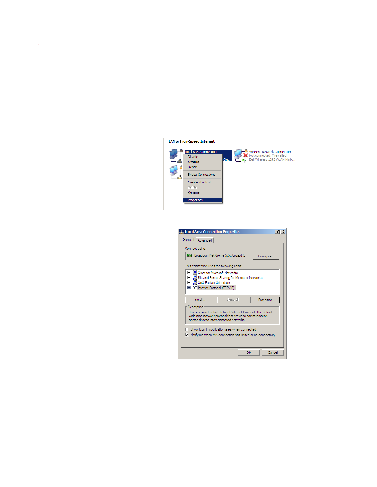
1. Open Network Connections in the Control Panel on your PC.
2. Right-click the icon for your local area network connection and select
Properties.
3. Click Internet Protocol, then click Properties.
Page 13
Getting Started
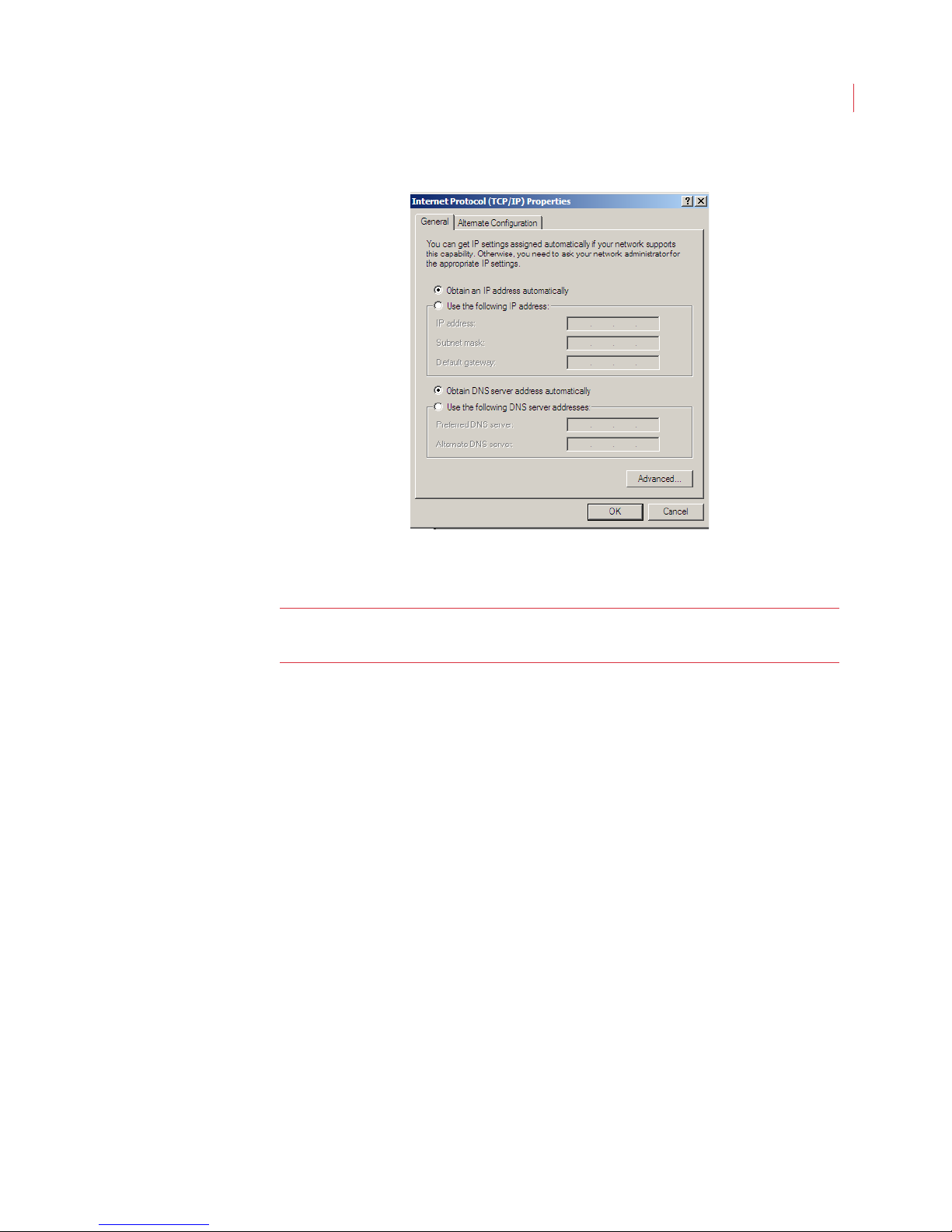
4. Verify that the Obtain an IP address automatically button is selected.
3
5. Click the Alternate Configuration tab and verify the Automatic Private IP
address option is selected.
Note: The iCVR uses zeroconf for auto discovery. An IP address in the
169.254.x.x range will automatically be assigned to the iCVR.
Discovering the iCVR’s DHCP Assigned IP Address
The first time a camera is turned on it’s configured for DHCP. If there is a DHCP
server available to give it an address, the camera will acquire that address. If
there is not a DHCP server on the network, the camera will automatically acquire
the following:
IP Address:169.254.238.51
Subnet Mask:255.255.0.0
This is the same subnet that Windows defaults to when it cannot find a DHCP
server. Therefore both devices default to the same network and will be able to
communicate.
Configuring Port Forwarding
Software ports are numbered connections that a computer uses to sort types of
network traffic. For security reasons, only common ports for services such as
HTTP or FTP are open by default; most other ports on routers are closed so that
unauthorized traffic cannot flow through them.
Port forwarding lets a router accept a connection request coming in on its WAN
(internet) interface and directs it to an IP address on its LAN (private network)
interface. When port forwarding is configured on a router, the router looks at the
Page 14

VideoIQ User Guide4
port number of a connection request coming in on its WAN port and forwards the
connection request to the appropriate IP address through its LAN port.
When you connect to iCVRs through the internet or across a WAN, your IT manager must configure the routers connected to the iCVRs for port forwarding. The
following ports are used for each iCVR:
Port Function Default Value Type
Control Port Secure communication
between View and the iCVR
takes place through this port
HTTPS Port Encrypted file transfer and
web access to the camera
take place through this port.
Choose to run the camera over
HTTPS or HTTP
HTTP Port File transfer and web access
to the camera take place
through this port. Choose to
run the camera over HTTP or
HTTPS.
RTSP Port Data that controls the video
stream goes through this port.
Audio Output Port When a speaker is attached to
the iCVR, audio transmits
through this port.
5401 TCP
443 TCP
80 TCP
554 UDP and TCP
20022 UDP
Aiming the Camera for Best Performance
Selecting the right field of view will make a significant difference in performance.
The key factors to consider when positioning an iCVR are:
Object Size: In order for an object to be accurately classified, its height
should be greater than 20 pixels (about 1/20th the height of the image)
and less than 320 pixels (about 2/3rd the height of the image).
Expected Object Velocity: The iCVR needs to be able to observe a
moving object for approximately 2 seconds before classifying it. Fast
moving vehicles might require a wider field of view so that the iCVR is
able to observe them for more than a few frames.
Blockages: An object needs to appear unblocked for several frames in
order for its classification to be accurate. When the iCVR is used
outdoors, it is acceptable for an object to be blocked during some part of
the time that it’s in the field of view, but a full view of the object is
necessary for a good fraction of that time. When the iCVR is configured
for indoor analytics, it can detect the head and shoulders of a person.
Angle and Perspective: The iCVR expects the ground plane to be
roughly horizontal, i.e., people walking in the field of view are mostly
upright and don’t appear to be tilted due to perspective distortion. The
Page 15

Getting Started
system will function accurately if it is mounted roughly 10 feet or higher
from the ground and tilted no more than 60 degrees off horizontal.
Reflected light: The iCVR should be positioned so that light sources,
including the sun, don’t shine directly into the lens. Indirect light sources
should also be carefully considered. While the iCVR uses an ultra wide
dynamic range imager, optical imperfections in the enclosure or the lens
might temporarily blind it.
5
Page 16
2
Installing the iCVR Camera
This chapter describes:
iCVR Camera Connections
Installing Your iCVR
Selecting the Best Camera Preset
Focusing Your Camera
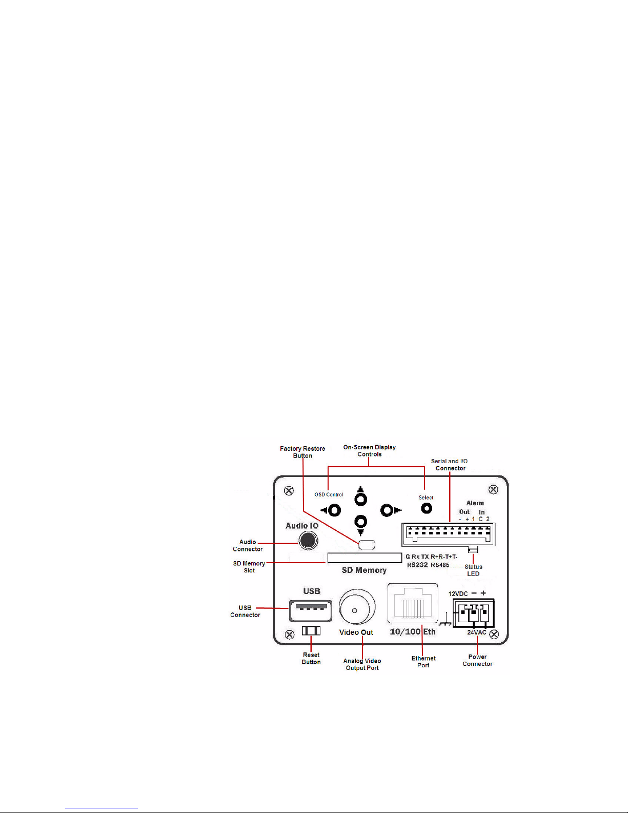
iCVR Camera Connections
Page 17

VideoIQ User Guide7
iCVR Connections Function
On-Screen Display Controls Allows you to navigate the on-screen menu of the iCVR with
the Up/Down/Left/Right/Select buttons. You must hold the
Select button for the on-screen menu to display.
SD Memory Slot Used only with the diskless iCVR for optional video storage.
Audio Connector Output port that allows you to connect a speaker and stream
audio.
Soft Reset Button Allows you to reboot the camera.
Factory Restore Button When used in conjunction with the soft reset button, returns
the camera to its default settings and clears all stored
settings and video.
USB Connector Used for iCVR image upgrades when upgrade doesn’t take
place through the View software.
Analog Video Output Port Allows you to view video on a standard analog monitor.
Ethernet Port Used for network communications, and can also be used to
power the iCVR (PoE).
Power Connector Connection for 12V DC or 24V AC power (connectors
included).
Serial and I/O Connector Provides connection for 2 alarm inputs and 1 alarm output,
along with RS-485 and RS-232 data communication.
Status LED Displays as red when the camera is starting up; displays as
green when the camera is ready.
Installing Your iCVR
1. Install a C- or CS-mount lens on your iCVR. When using a C-mount lens, first
insert the included 5mm spacer, and then install the lens.
Use a manual iris lens for indoor applications.
Use an auto-iris lens for outdoor use.
2. After mounting the lens, connect the auto-iris cable to the port on the side of
the camera.
3. Mount the iCVR for best detection of the scene. When installed outside or in
a dusty, cold or humid environment, you should protect the iCVR camera with
a weather-proof housing heater and cooler, such as the VIQ-HO-SHF24.
4. Connect your iCVR to the IP network with an Ethernet cable.
5. Connect audio, alarm, and other connections if needed.
6. Connect a portable analog monitor to the Video Output port.
7. Connect power to you iCVR. You can use:
Power over Ethernet (802.3af class 3)
12 VDC (use the included connector)
24 VAC (use the included connector)
Page 18
Installing the iCVR Camera
You can connect more than one power supply if redundant power is desired. The
iCVR will switch over to the second power source automatically if the first power
source is lost.
Note: When the iCVR is powered up, it displays its IP address for three minutes.
Record this address for future use.
Selecting the Best Camera Preset
The iCVR bundles an extensive range of electronic settings in four easy-to-use
presets. In most cases the preset value is the only camera setting you need to
change. You can access these options through the on-screen display:
8
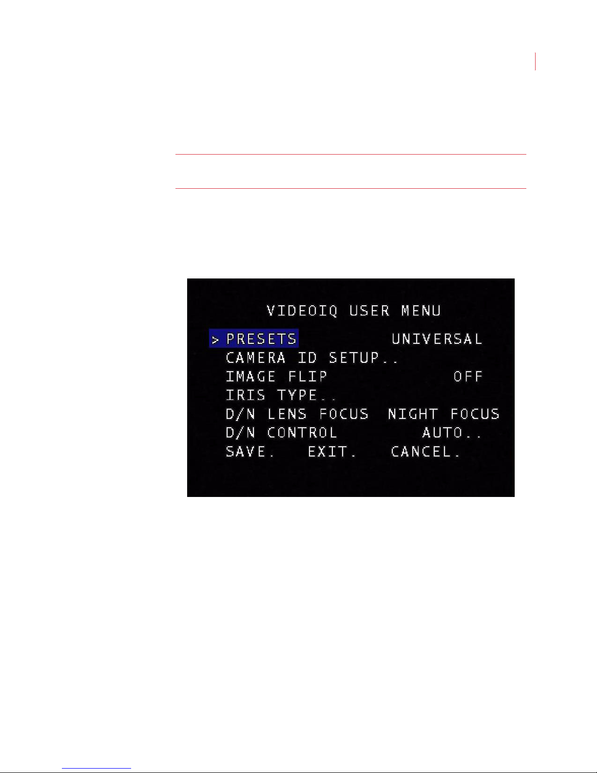
1. Turn on the on-screen display by holding down the Select button on the back
of the camera for five seconds. The cursor should be positioned on the
PRESETS option.
2. Use the right arrow button on the back of the camera to select one of the
following options:
UNIVERSAL: This is the default setting and is ideal for mixed
INDOOR: For indoors with incandescent or high energy lighting.
FLUORESCENT: For indoors with fluorescent lighting.
OUTDOOR: For all outdoor applications.
3. Press the down button until you reach SAVE. Press the Select button to save
all your settings.
environments, such as indoors with nearby windows.
Page 19
VideoIQ User Guide9
Note: You can change the camera presets and settings remotely from the
VideoIQ View administration application. See Chapter 9: Administering
Cameras.
Focusing the Camera
1. Use your portable analog monitor to aim the camera and adjust the lens’ field
of view and focus for the clearest picture.
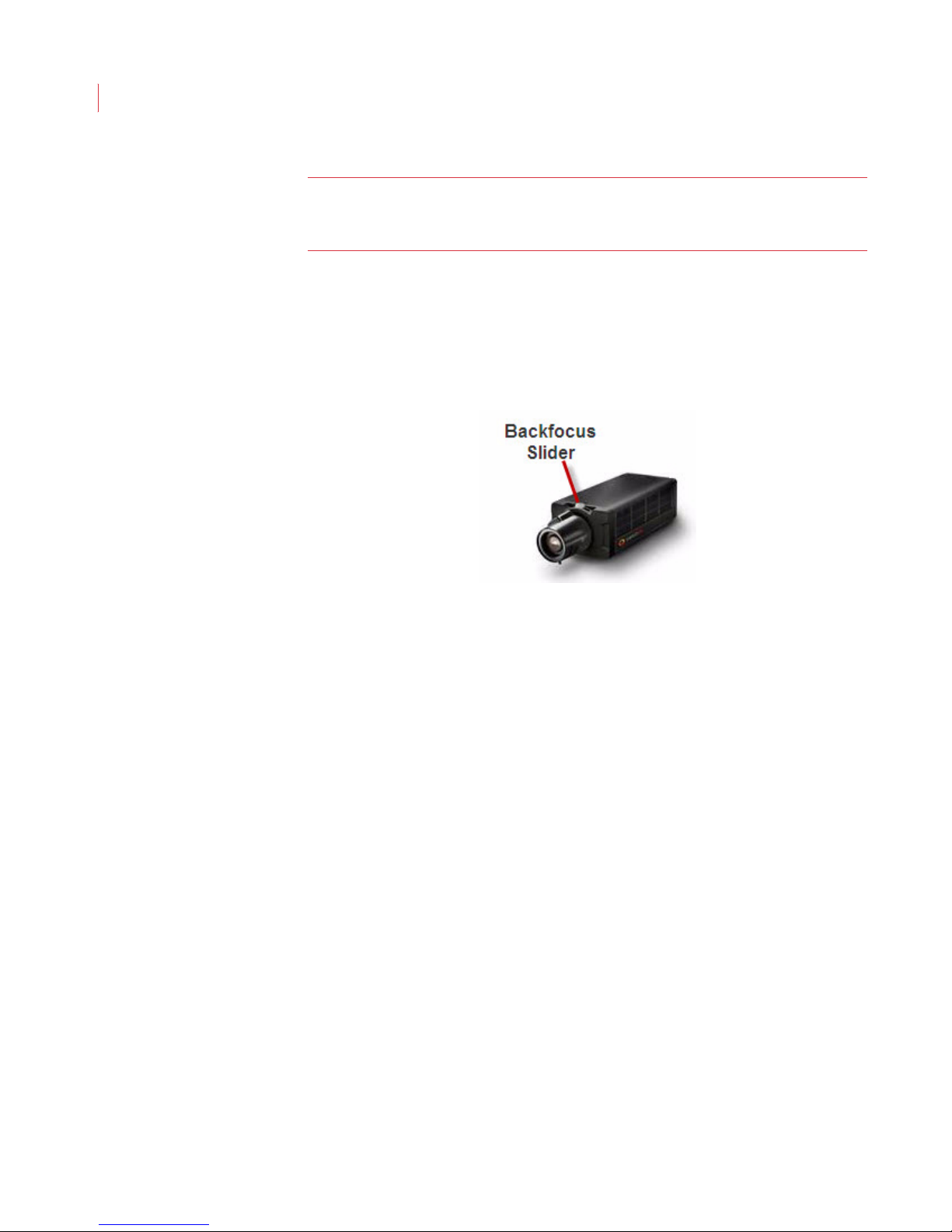
3. Change the position of the back-focus slider if you need to extend the focus
range of your lens.
4. If you are using a manual lens, manually adjust the iris for optimum night-
viewing, and focus the lens.
5. If you are using an auto-iris lens, open the iris completely before focusing the
camera to assure proper focus at night. The iCVR comes equipped with an
easy way of doing this:
a. Turn on the on-screen display menu (see above).
b. Press the down button to scroll to IRIS TYPE and verify that it is set for
AUTO.
c. Press the down button to scroll to D/N LENS FOCUS.
d. Press the right arrow button until NIGHT FOCUS is selected. This opens
the iris fully to simulate nighttime.
e. Focus the lens for the best possible overall clarity.
f. Press the right arrow button to select DAY FOCUS. Verify the focus.
g. Repeat DAY and NIGHT settings until focus is optimized for all conditions.
6. When focus is complete, set it back to DAY FOCUS for normal auto-iris oper-
ation.
7. When you are finished, press the down arrow to scroll to SAVE. Press the
SELECT button to save your settings.
Page 20
3
Installing the iCVR Encoder
This chapter describes:
iCVR Encoder Connections
Connecting the Encoder to a Camera
Connecting a PTZ Camera to the Encoder
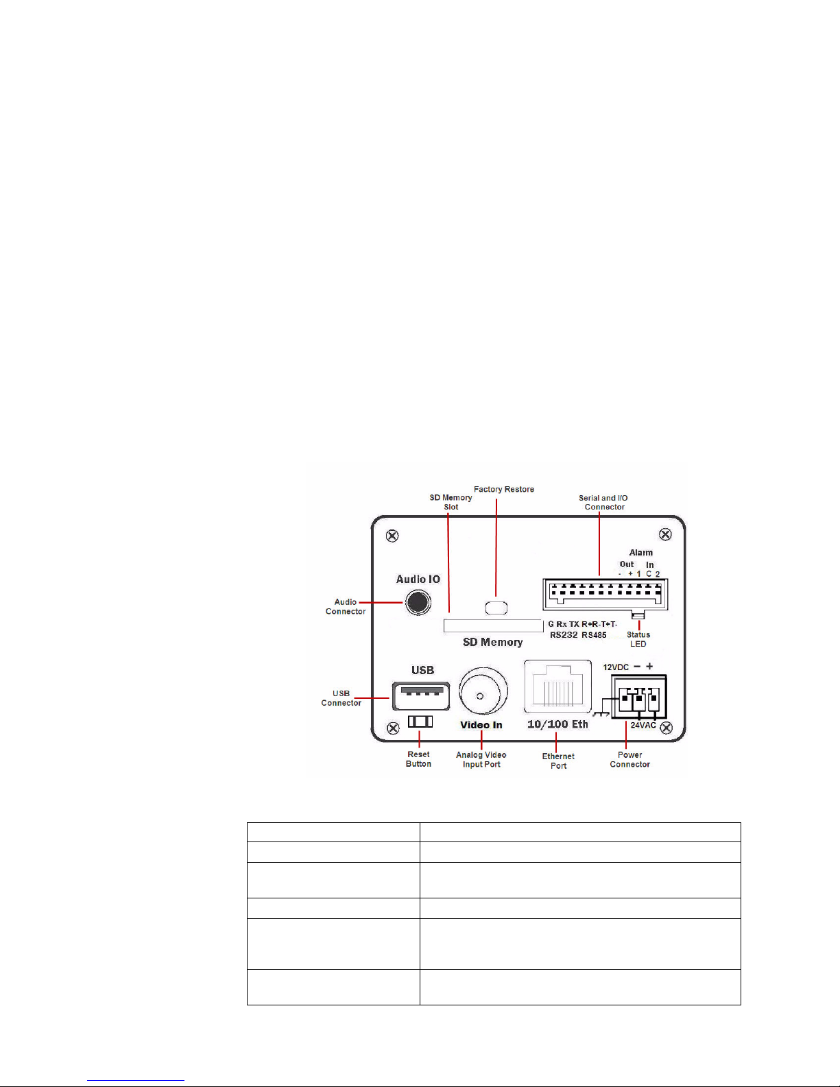
iCVR Encoder Connections
iCVR Connections Function
SD Memory Slot Used only with the diskless iCVR for optional video storage.
Audio Connector Output port that allows you to connect a speaker and stream
Reset Button Allows you to reboot the camera.
Factory Restore Button When used in conjunction with the soft reset button, returns
USB Connector Used for iCVR image upgrades when upgrade doesn’t take
audio.
the camera to its default settings and clears all stored
settings and video.
place through the View software.
Page 21

VideoIQ User Guide11
iCVR Connections Function
Analog Video Input Port Allows you to view video on a standard analog monitor.
Ethernet Port Used for network communications, and can also be used to
power the iCVR (PoE).
Power Connector Connection for 12V DC or 24V AC power (connectors
included).
Serial and I/O Connector Provides connection for 2 alarm inputs and 1 alarm output,
along with RS-485 and RS-232 data communication.
Status LED Displays as red when the camera is starting up; displays as
green when the camera is ready.
Connecting the Encoder to a Camera
The VideoIQ Encoder lets you use any standard analog security camera as an
iCVR. To connect a camera to the Encoder you will need a:
75 Ohm coaxial cable
Ethernet cable
Power:12 VDC, 24 VAC or Power over Ethernet
1. Connect the coaxial cable to the Video In port of the Encoder and the
Video Out port of the camera.
2. Connect the Encoder to the IP network with an Ethernet cable.
3. Connect power to the Encoder. You can use one of the following:
Power over Ethernet (802.3af class 3)
12 VDC (use the included connector)
24 VAC (use the included connector)
You can connect more than one power supply if redundant power is desired. The
iCVR will switch over to the second power source automatically if the first power
source is lost.
Connecting a PTZ Camera to the Encoder
When connecting a PTZ camera to the Encoder you will need the coaxial and
Ethernet cables listed above, as well as a:
Two-wire cable for a half-duplex PTZ
or
Four-wire cable for a full-duplex PTZ
1. Follow steps 1-3 above.
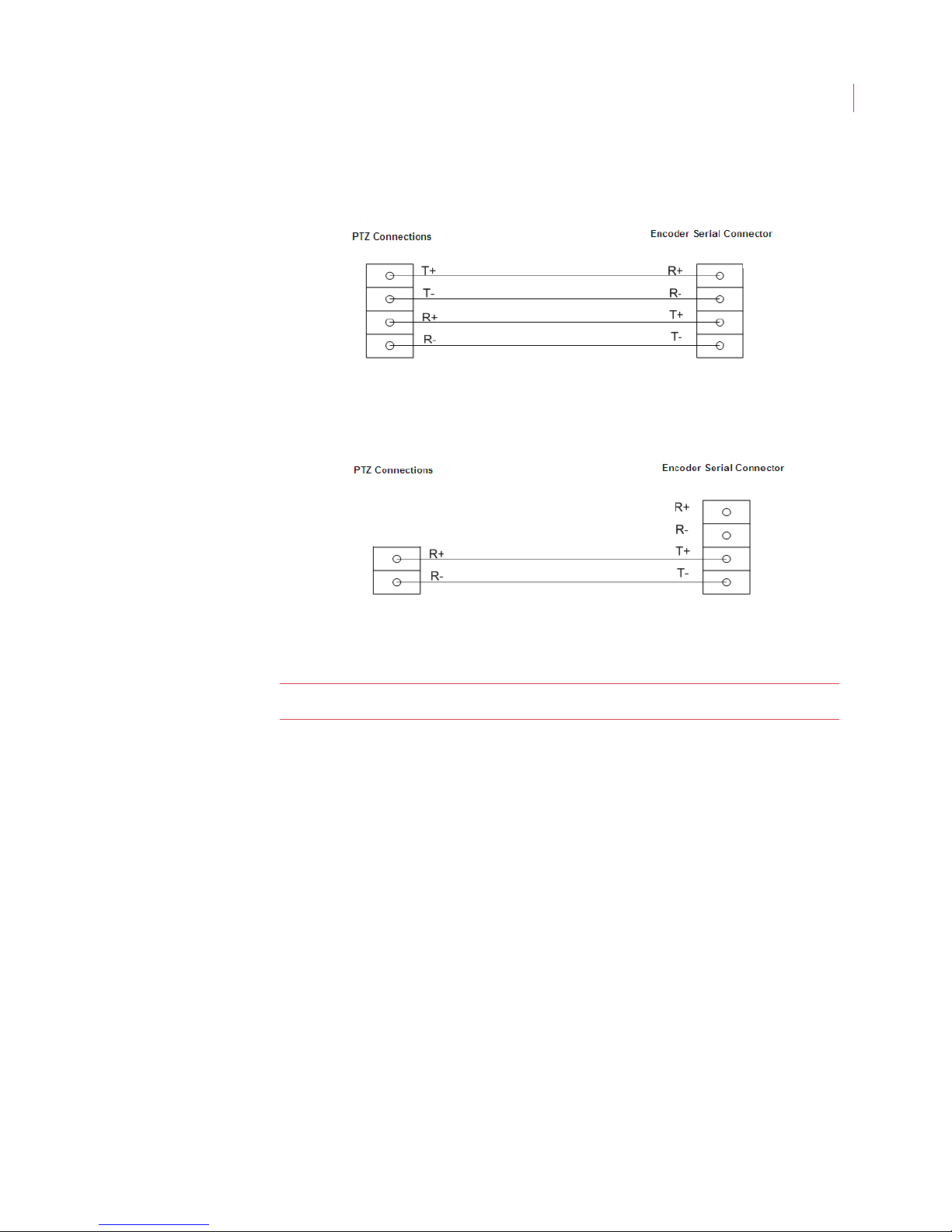
2. For a full-duplex camera, connect the four-wire cable to the serial
connector on the back panel of the Encoder and to the PTZ camera. The
T+ and T- cables from the PTZ should connect to the R+ and R- slots on
Page 22
Installing the iCVR Encoder
the Encoder serial connector, and the R+ and R- cables from the camera
should connect to the T+ and T- slots.
3. For a half-duplex camera, connect the R+ and R- cables from the camera
to the T+ and T- slots on the Encoder.
12
Once the camera has been connected to the Encoder see Configuring Encoder
Settings on page 43 to use the View software features.
Note: The Encoder supports only Pelco P and Pelco D PTZ cameras.
Page 23

4
Installing a Dome Camera
This chapter describes:
Dome Camera Connections
Installing a Dome Camera
Selecting the Best Camera Preset
Adjusting and Focusing the Camera
Page 24
VideoIQ User Guide14
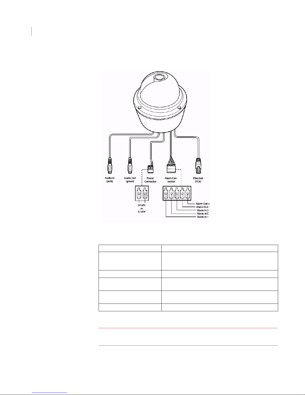
Dome Camera Connections
Dome Connections Function
Audio Connector Connection cable that allows you to connect a microphone
Line Out Connector Connection cable that allows you to connect a speaker.
Ethernet Port Used for network communications, and can also be used to
Power Connector Connection for 12V DC or 24V AC power (connectors
Alarm I/O Connector Provides connection for 2 alarm inputs, 1 alarm output.
Note: The illiustration above shows an outdoor dome camera. Indoor dome
and use the Talk button on the Alarm screen to stream
audio.
power the iCVR (PoE).
included).
camera do not include all of the connections pictured.
Page 25
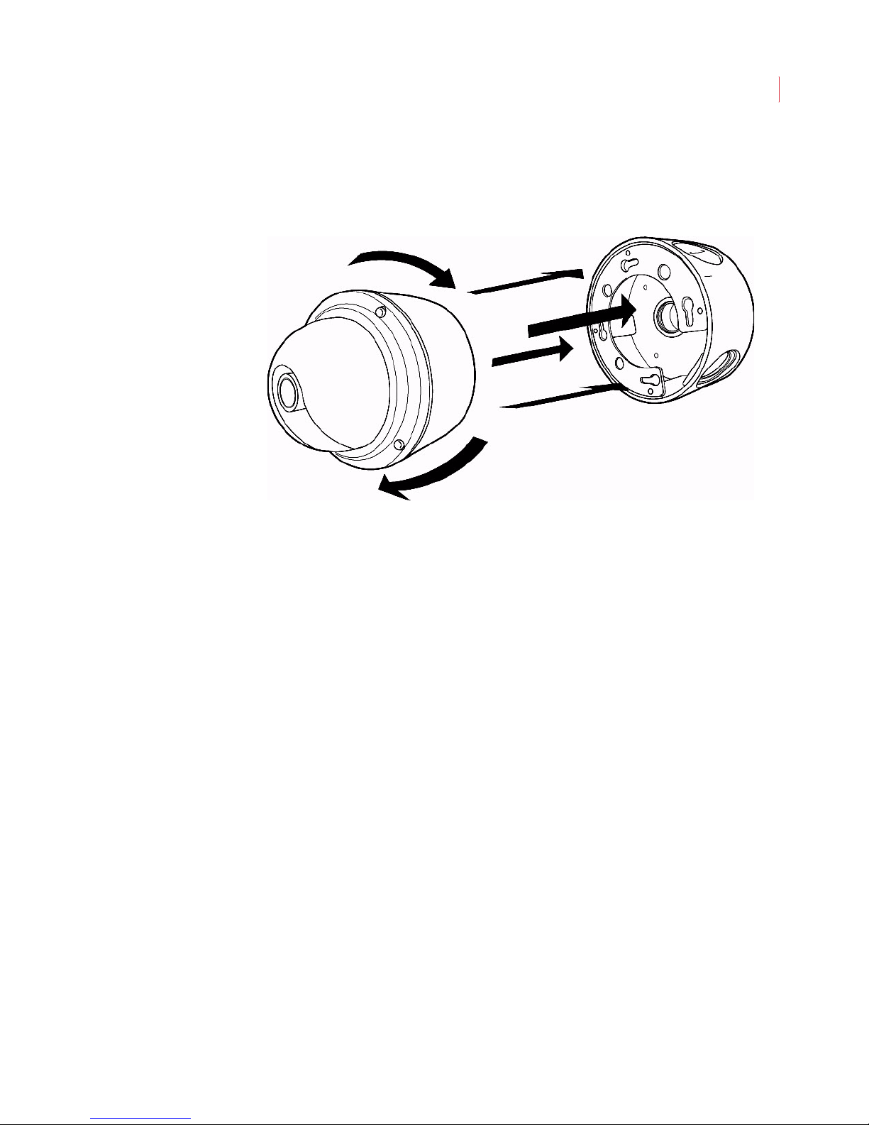
Installing a Dome Camera
Surface Mount
Installing a Dome Camera
15
1. Determine where you want to mount the camera. Peel the back off of the
adhesive alignment template and place it on the wall.
2. Drill pilot holes using the drill guide marks.
3. Align the holes in the back of the mount base with the holes on the wall.
4. Use the enclosed screws to attach the mount base to the wall.
5. Thread the cables into the mount base.
6. Align the spring-loaded fasteners on the back of the camera with the keyholes
on the mount.
7. Turn the camera clockwise until it locks in place.
8. Point and focus the lens using the steps below.
Page 26
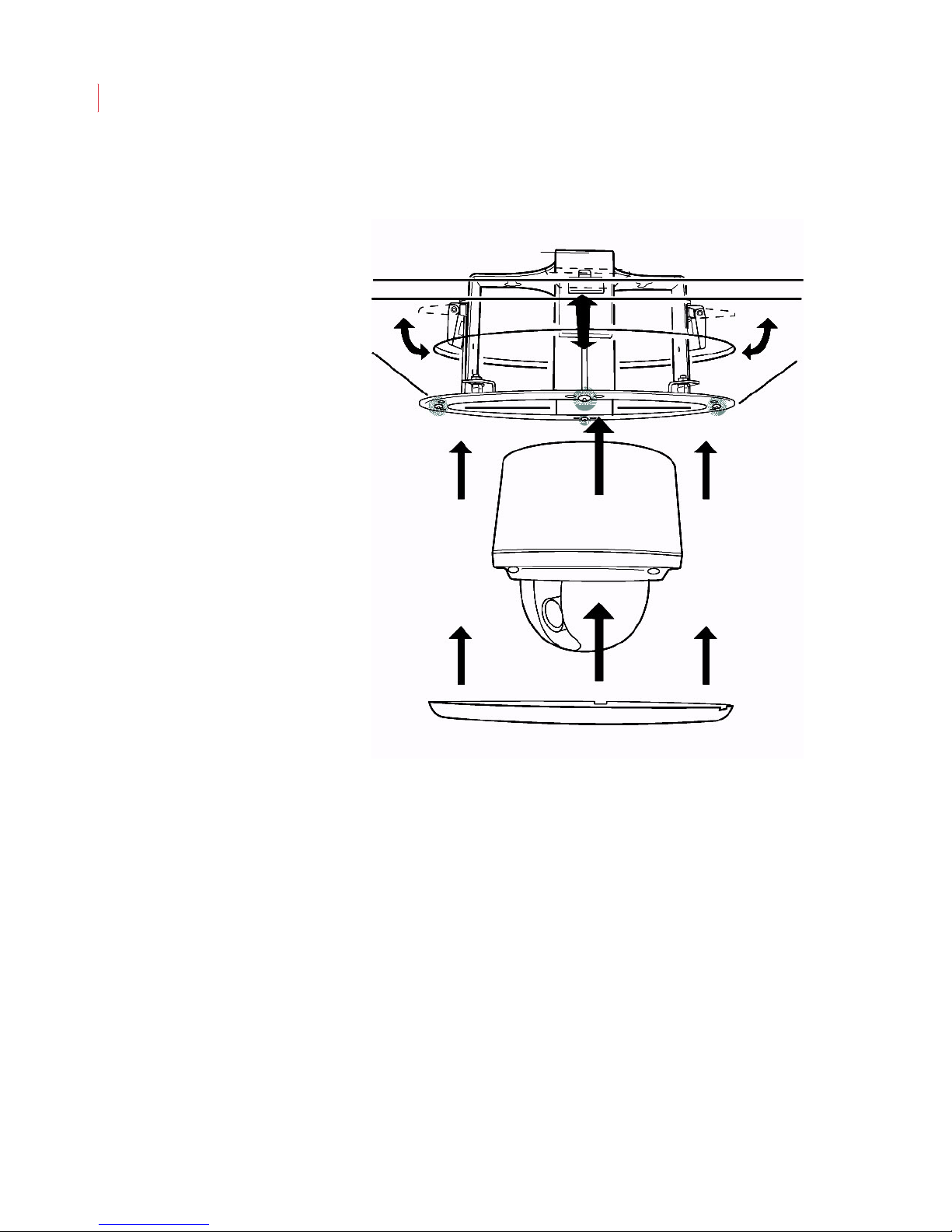
VideoIQ User Guide16
Flush Mount
1. Determine where you want to mount the camera. Peel the back off of the
2. Insert the mounting plate into the ceiling hole and tighten the support screws
3. Thread the cables through the mounting plate.
4. Align the spring-loaded fasteners on the back of the camera with the keyholes
5. Turn the camera clockwise until it locks in place.
6. Point and focus the lens using the steps below.
7. Place the trim ring over the dome of the camera, aligning the locking tabs with
adhesive ceiling hole template and place it on the ceiling. Cut away the ceiling
material.
(highlighted).
on the mounting plate.
the slots on the mounting plate. Press down.
Page 27
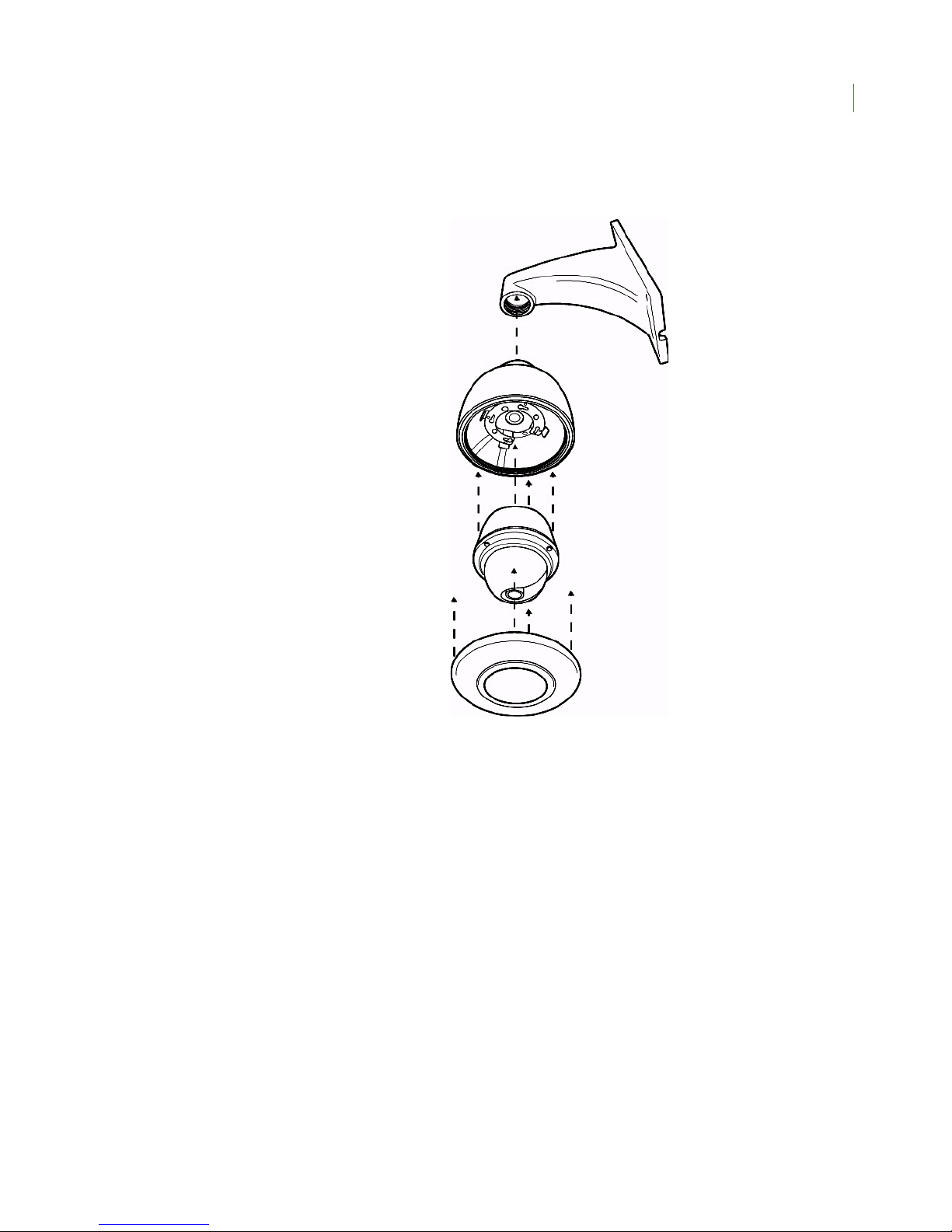
Pendant Mount from the Wall
Installing a Dome Camera
17
1. Determine where you want to mount the camera. Place the mount plate
against the wall and secure it using the enclosed screws. You may need to
drill pilot holes.
2. Thread the cables through the mount plate.
3. Place the camera inside the pendant, running the camera cables through the
opening at the top of the pendant.
4. Align the arrow on the front of the camera dome with the arrow on the rim of
the pendant.
5. Turn the camera clockwise until it locks in place.
6. Screw the pendant into the arm of the mount plate.
7. Tighten the set screws on the front of the arm.
8. Point and focus the lens using the steps below.
9. Attach the trim ring to the bottom of the pendant.
Page 28
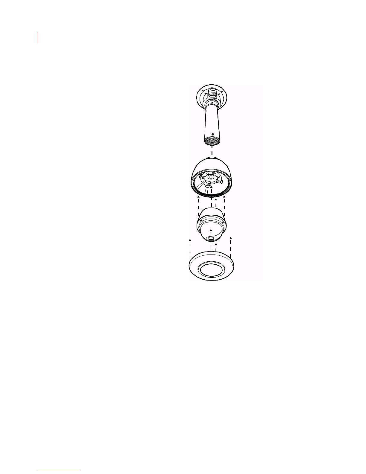
VideoIQ User Guide18
Pendant Mount from the Ceiling
1. Determine where you want to mount the camera. Place the mount plate
against the ceiling and secure it using the enclosed screws. You may need to
drill pilot holes.
2. Thread the cable connections through the side of the ceiling mount plate.
Thread them through the extension tube; then screw the tube into the mount
plate.
3. Place the camera inside the pendant, running the camera cables through the
opening at the top of the pendant.
4. Align the arrow on the front of the camera dome with the arrow on the rim of
the pendant.
5. Turn the camera clockwise until it locks in place.
6. Screw the pendant into the extension tube.
7. Point and focus the lens using the steps below.
8. Tighten the set screws on the mount plate and extension tube.
9. Attach the trim ring to the bottom of the pendant.
Page 29
Installing a Dome Camera
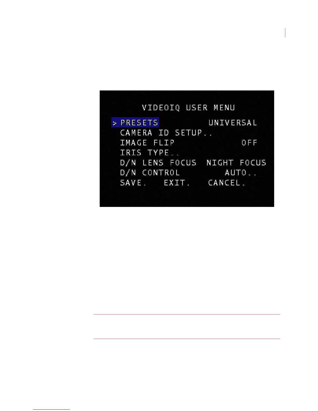
Selecting the Best Camera Preset
The iCVR bundles an extensive range of electronic settings in four easy-to-use
presets. In most cases the preset value is the only camera setting you need to
change. You can access these options through the on-screen display:
19
1. Turn on the on-screen display by holding down the Select button on the
service board of the camera for five seconds. The cursor should be
positioned on the PRESETS option.
2. Use the right arrow button on the back of the camera to select one of the
following options:
UNIVERSAL: This is the default setting and is ideal for mixed
environments, such as indoors with nearby windows.
INDOOR: For indoors with incandescent or high energy lighting.
FLUORESCENT: For indoors with fluorescent lighting.
OUTDOOR: For all outdoor applications.
3. Press the down button until you reach SAVE. Press the Select button to save
all your settings.
Note: You can change the camera presets and settings remotely from the
VideoIQ View administration application. See Chapter 9: Administering
Cameras.
Page 30
VideoIQ User Guide20
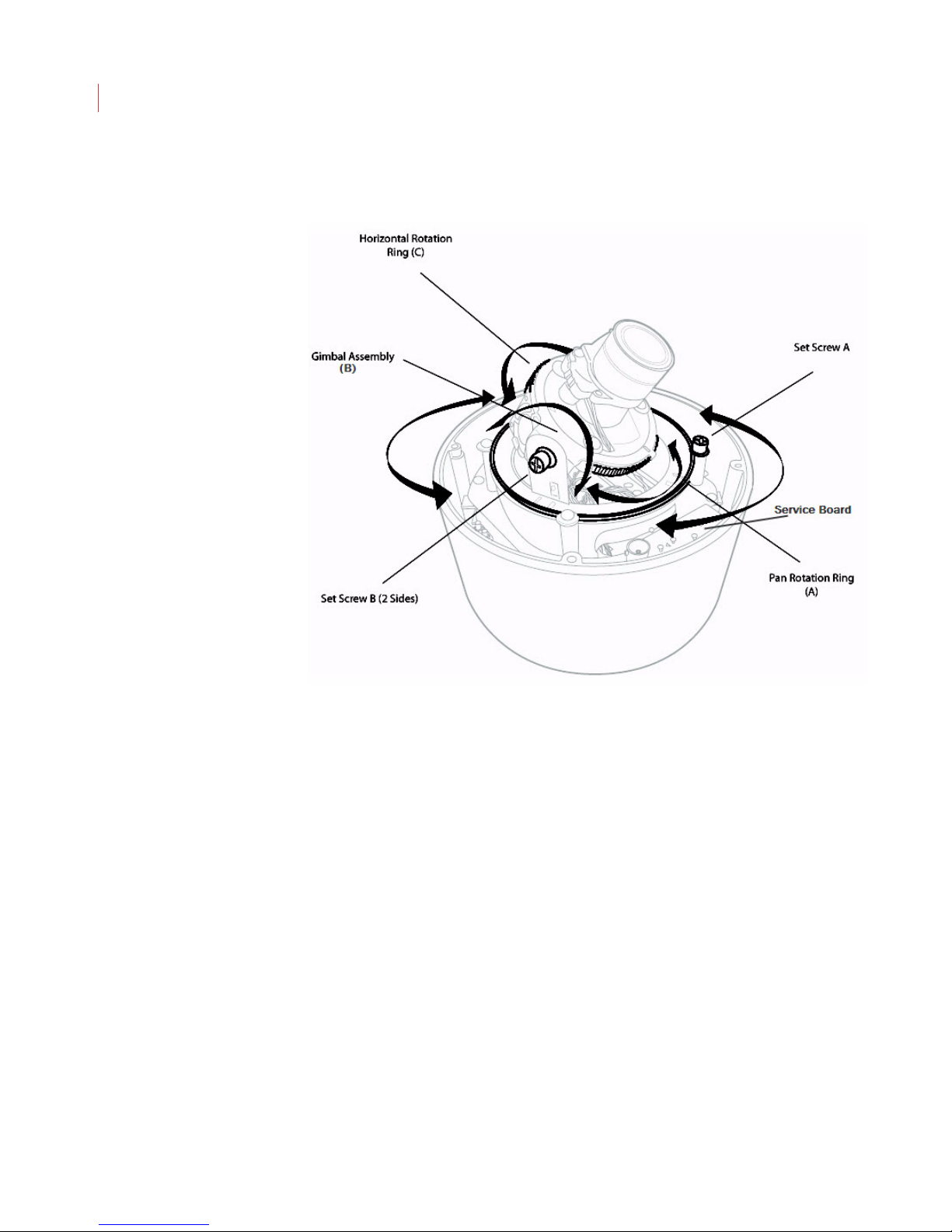
Adjusting and Focusing the Camera
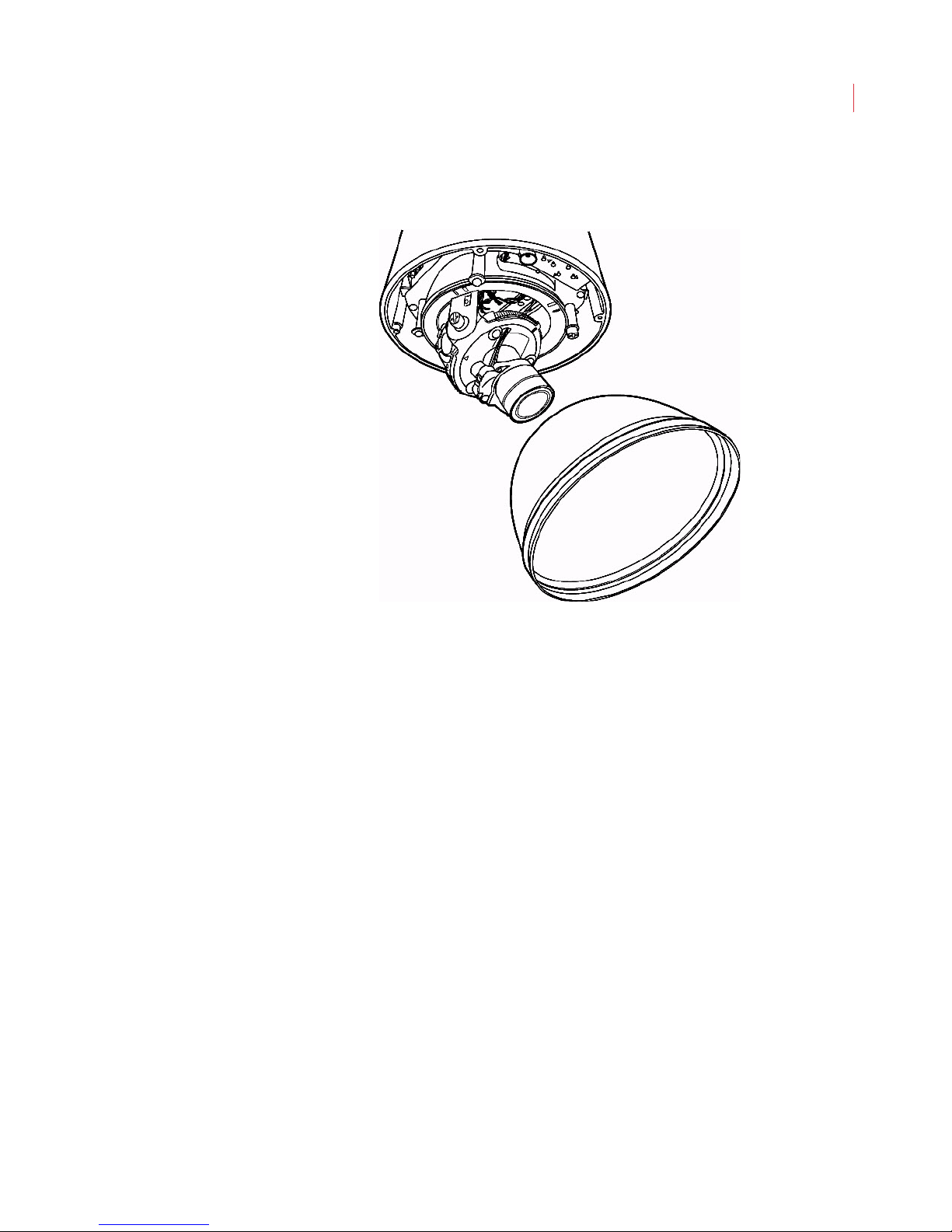
1. Remove the dome cover from the camera.
2. Move the lens into the desired postion by loosening set screw A, adjusting the
pan rotation ring (A), then tightening the set screw.
3. Loosen set screw B on either side of the gimbal assembly, tilt the lens to the
desired position (B), then tighten the set screws.
4. If the image is inverted or not completely aligned, adjust the horizontal rotation
ring (C).
5. Zoom to the desired field of view by loosening the outermost set screw on the
lens, adjusting the zoom, then tightening the set screw.
6. Focus the lens by loosening the screw on the focus ring; adjusting the focus,
then tightening the screw.
Page 31
Installing a Dome Camera
While adjusting the focus and zoom, hold the spare dome over the lens to
simulate conditions when the dome has been installed.
21
7. Replace the dome cover and tighten the screws.
Page 32

5
Installing and Uninstalling View
This chapter describes:
System Requirements
Installing the View Software
Uninstalling View
System Requirements
To run the View software you will need:
Windows XP (with Service Pack 2 or higher) or Vista (with Service Pack
1)
Core-2 Duo 2.0 GHz processor or better
At least 2 GB of RAM
A network connection between your PC and the cameras you want to
access.
10 GB of disk space for clip downloads.
PC monitor with a minimum of 900 pixels vertical display resolution.
Installing the View Software
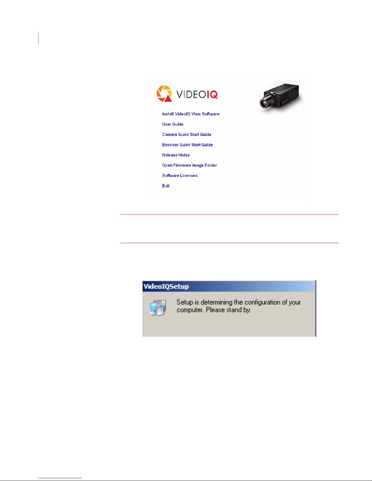
1. Insert the VideoIQ View installation disk in the CD drive of your computer.
Note: When installing View you must be logged into the PC as the administrator.
Page 33
VideoIQ User Guide23
2. When the installer window appears, click Install VideoIQ View Software.
Note: If the installer does not automatically start, your auto-play feature may be
disabled. Access the installation CD directly and double-click the
VideoIQViewInstaller application icon.
3. The VideoIQ View installer reviews the software installed on your
computer to determine its installation requirements.
Page 34
Installing and Uninstalling View
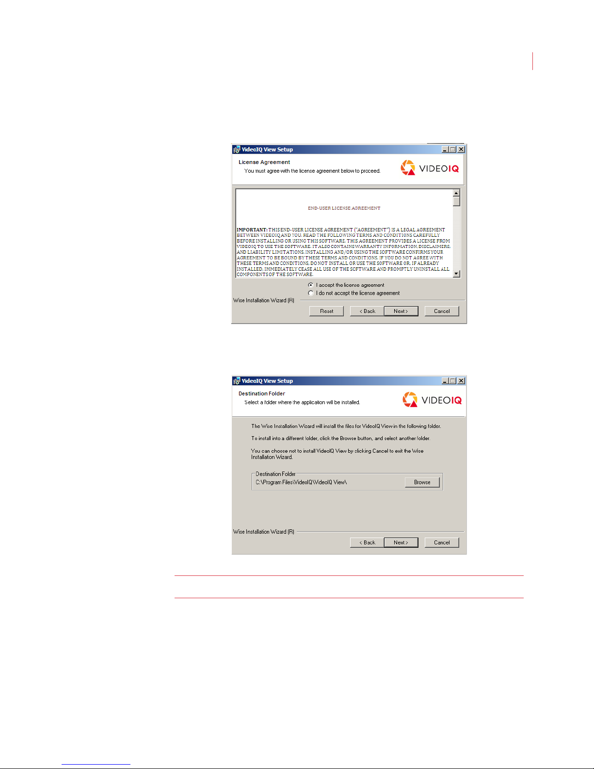
4. Review the end user license agreement. Select “I accept the license
agreement” and click Next. If you choose not to accept the license
agreement the installation is cancelled.
24
5. The software is installed in the C:\Program Files directory of your
computer by default. If you want it installed in a different directory, click
the Browse button and navigate to the new location.
Note: View must be installed on a local drive, not on a network drive.
6. The installer automatically installs the View software and the supporting
software required to run the View application. If none of the supporting
software is installed on your PC it can take up to 15 minutes to complete
the installation.
Page 35
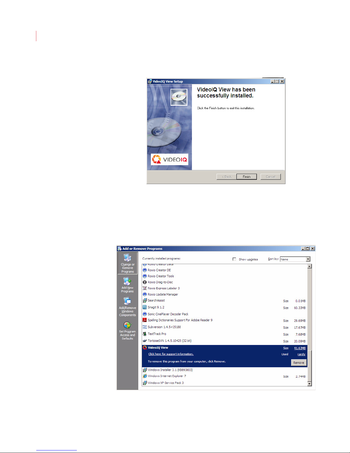
VideoIQ User Guide25
7. Click Finish when the View Setup window indicates your software has
been installed.
Uninstalling View
If you want to uninstall the View software:
1. On your computer go to Start -> Control Panel-> Add or Remove
Programs.
2. Scroll to VideoIQ View and click Remove.
Page 36

Installing and Uninstalling View
3. You will be asked to confirm that you want View removed.
4. The uninstaller removes the View software from your computer.
26
Page 37

6
Using the View Interface
This section describes:
Running the View Application
View Toolbar
Video IQ Menu
Status Bar
Displaying Version Information
Exiting the View Application
Running the View Application
The VideoIQ View installer puts a VideoIQ icon on your computer desktop. To run
View:
1. Double-click the VideoIQ View icon.
2. When the Log In dialog opens, enter your username in the User Name field.
3. Enter your password in the Password field. If this is the first time you’re
logging in, use “supervisor” for the username and “supervisor” for the
password. Once you’ve logged in change the password for this default
account. See Chapter 7: User Accounts for information on changing
passwords.
4. Click OK.
Page 38
VideoIQ User Guide28
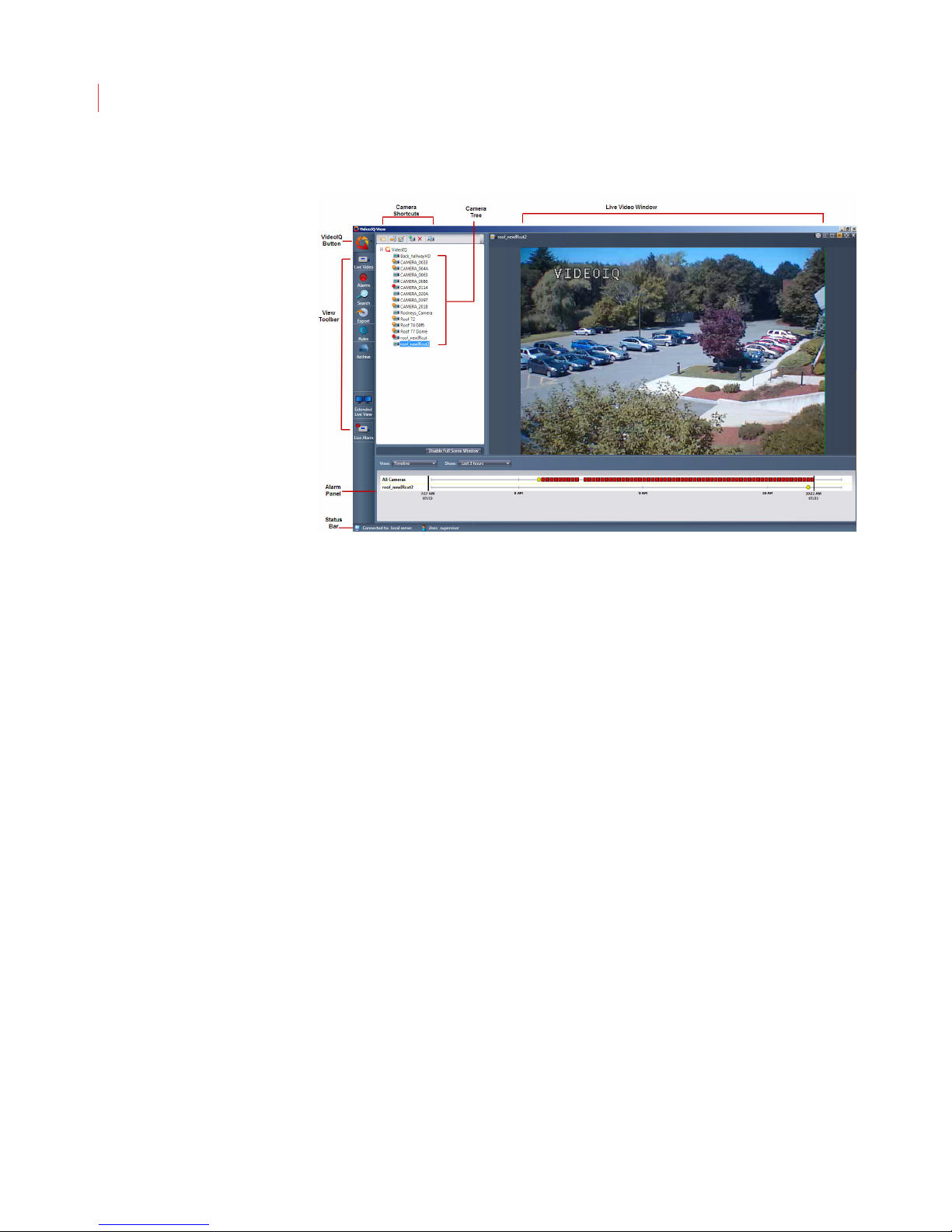
View Toolbar
Use the entries in the View toolbar to select which panel you want to display. For
example, to display the Live Video panel, click Live Video in the sidebar.
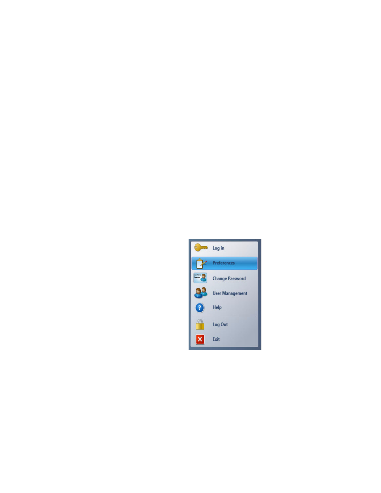
VideoIQ Menu
The VideoIQ menu can be accessed by clicking the VideoIQ button and consists
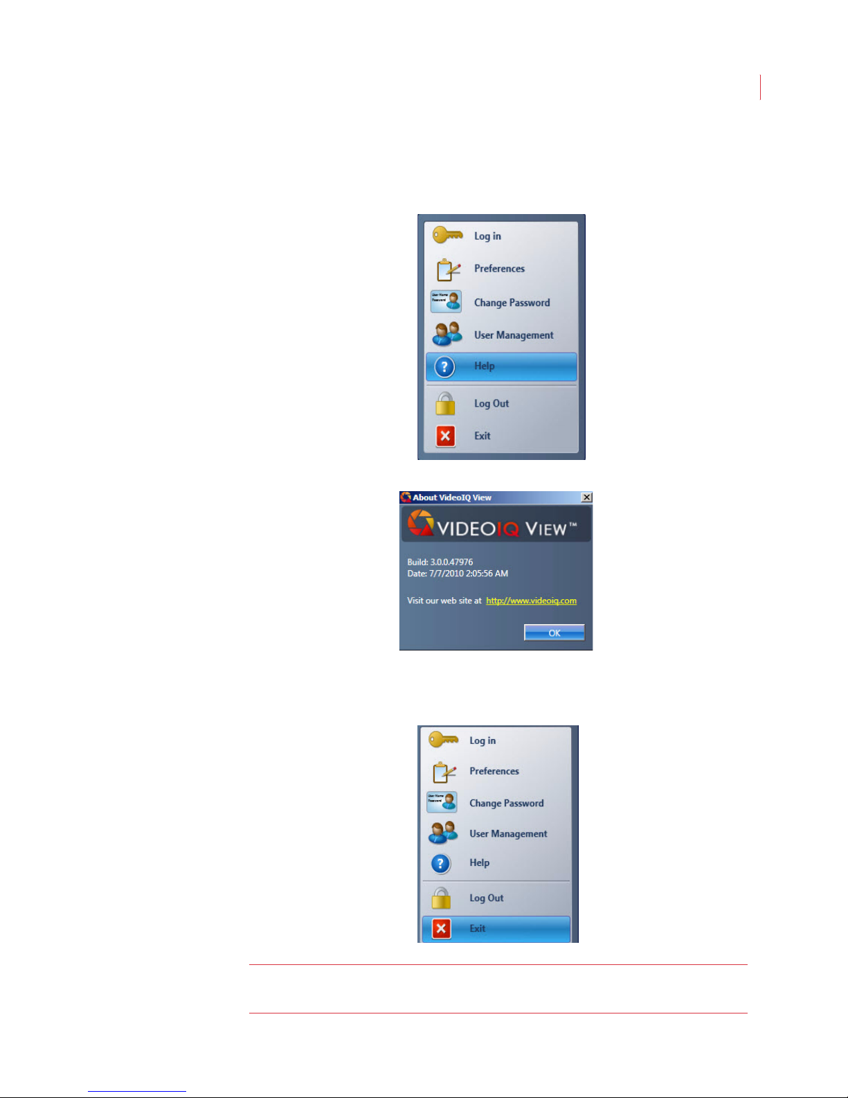
of the following entries:
Log In - Opens the Log In dialog, which allows you to log in as a different
user.
Preferences – Opens the Preferences window, allowing you to select
application preferences for View. The Preferences window is described in
Chapter 8: Configuring View Preferences.
Change Password – Opens the Change Password dialog box, allowing
you to modify the password associated with a user. The Change
Password dialog is described in Chapter 7: User Accounts.
User Management – Opens the User Manager dialog box which displays
your list of users; allows you to add a user or edit user information; modify
user permissions, and copy user accounts across cameras.
Help – Displays version information for the View application.
Log Off – Logs you out of View and leaves the application running.
Exit – Logs you out of View and shuts down the application.
Status Bar
The status bar displays the name of the VideoIQ server and the name of the user
who is currently logged in.
Page 39
Using the View Interface
Displaying Version Information
You can display version information for your View software by selecting Help from
the VideoIQ menu.
The application version number displays:
29
Exiting the View Application
To exit the View application, choose Exit from the VideoIQ menu.
Note: Closing the View application has no impact on the iCVRs running on your
network.
Page 40

7
User Accounts
This chapter describes:
Default User Accounts
Changing a Login Password
Adding a User Account
Copying User Accounts and Permissions From a Camera
Editing a User Account
Deleting a User Account
Modifying User Permissions
Default User Accounts
Each camera comes configured with two default user accounts: “supervisor” and
“operator”. After logging into View for the first time, a user with supervisor-level
permission should change the default password for both user accounts.
The default login credentials for these two users are:
supervisor/supervisor
operator/operator
Note: The default supervisor account should not be used for day-to-day
Changing a Login Password
Users with supervisor-level permission can change the login password for all
users.
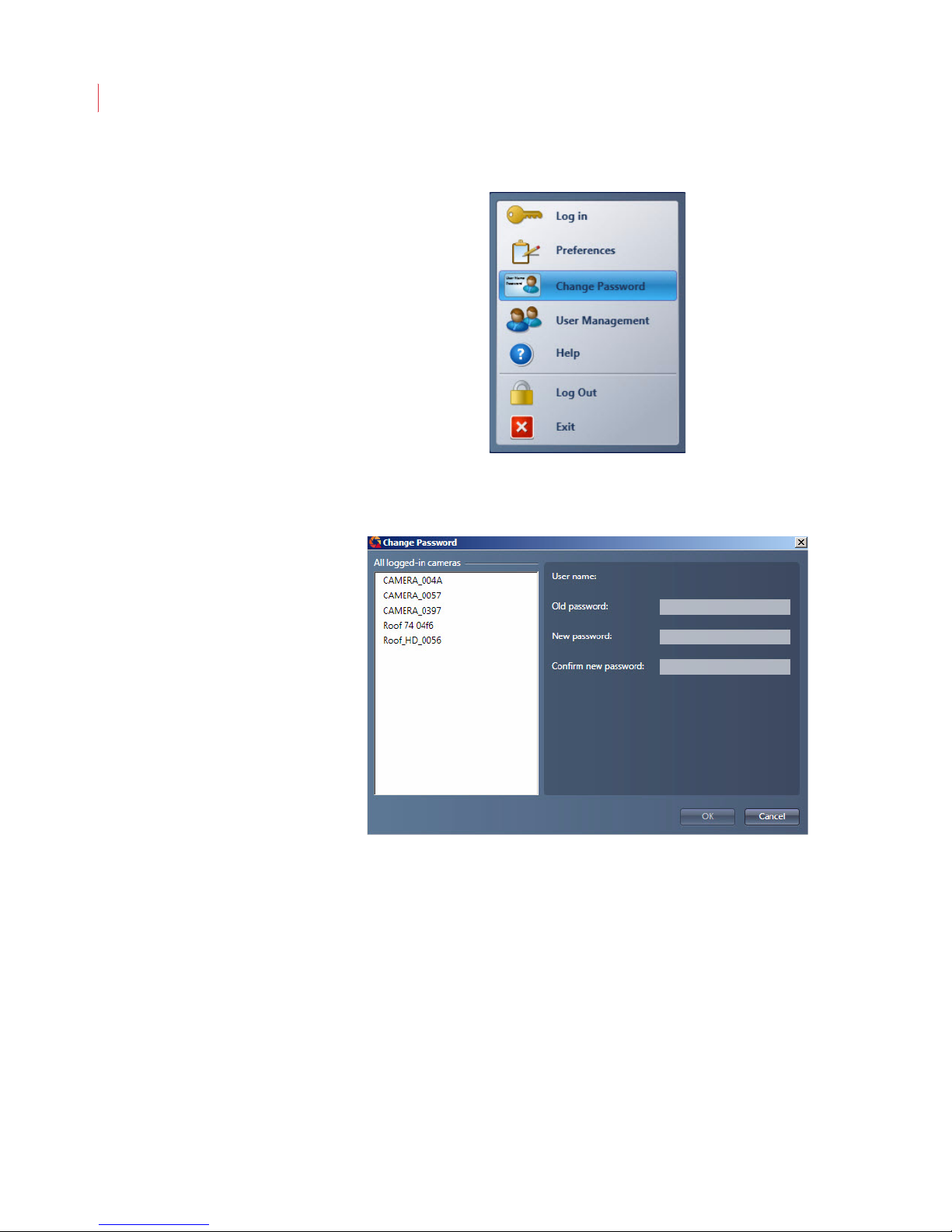
To change your own password:
1. Click the VideoIQ button and select Change Password.
activities. Users with supervisor-level accounts should have their own
username and password so that history logs will identify who made
changes to the system.
Page 41
VideoIQ User Guide31
2. When the Change Password dialog displays select the cameras where
you to want to change the password
.
3. Enter the old and new passwords. The password must be a minimum of 4
characters, can include both numbers and letters, and is case sensitive.
4. Confirm the new password.
5. Click OK.
Page 42
User Accounts
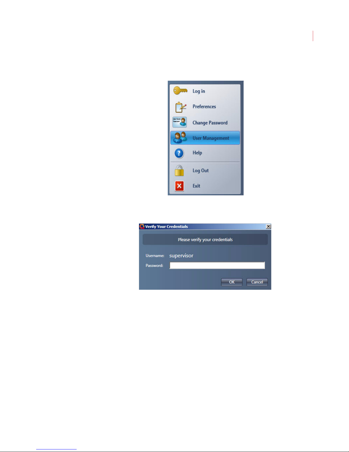
To change the password for another user:
1. Click the VideoIQ button in the toolbar and select User Management.
32
2. When the Verify Your Credentials dialog box displays enter your
Password and click OK.
If you have different logins on different cameras the dialog box will display a
username and password field for each camera.
Page 43
VideoIQ User Guide33
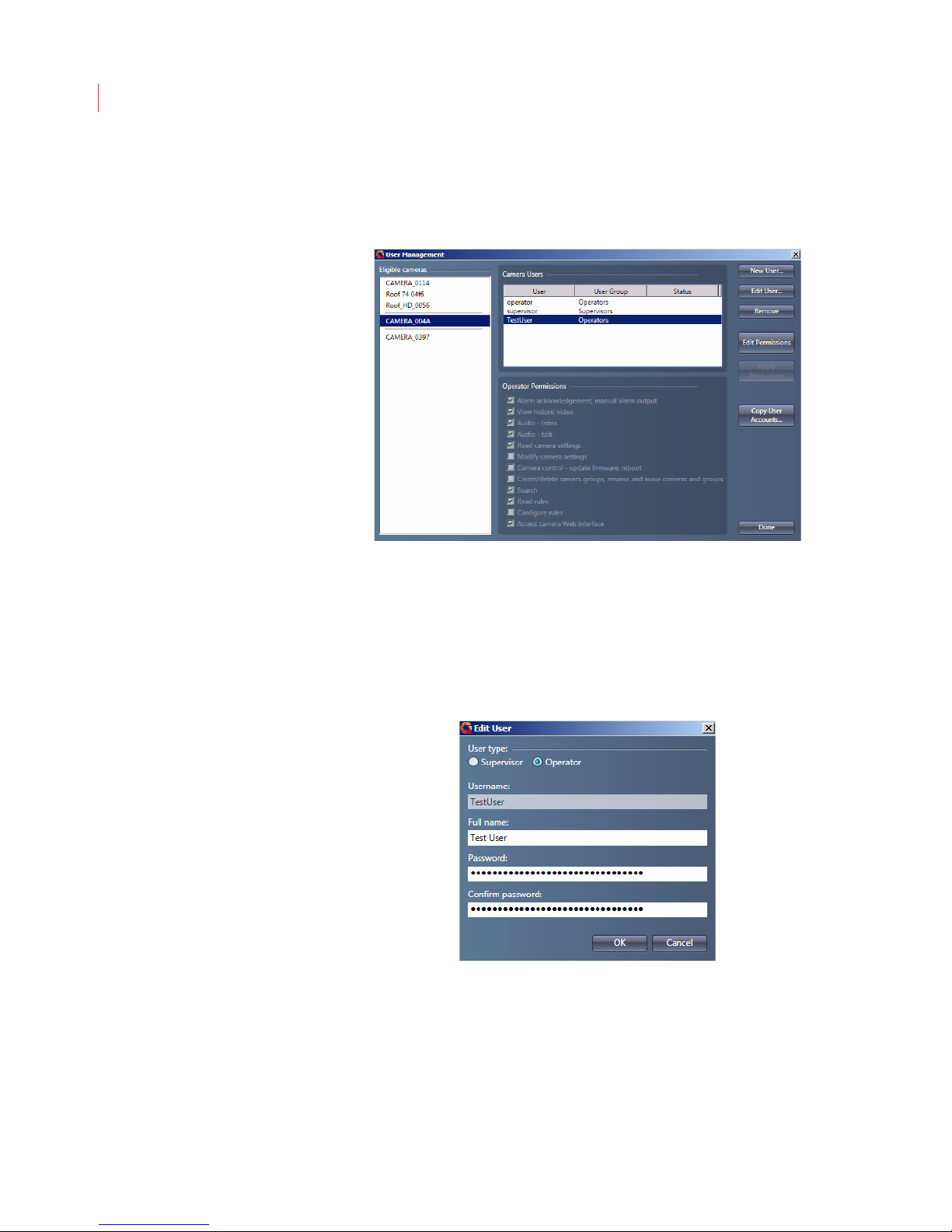
3. The User Management dialog box displays, showing all cameras you
have permissions on. Cameras are grouped together based on like
permissions or users.
4. Select a camera from the Eligible Cameras list.
5. Select a user from the Camera Users field.
6. Click Edit User.
7. Enter the old and new passwords for the user. The password must be a
minimum of 4 characters, can include both numbers and letters, and is
case sensitive.
8. Click OK.
Adding a User Account
You can add an unlimited number of user accounts to a camera:
Page 44
User Accounts
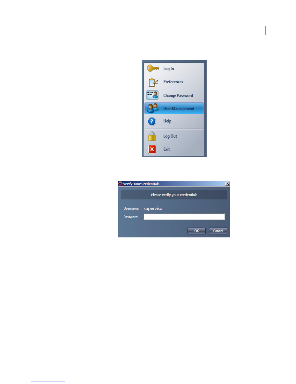
1. Click the VideoIQ button in the toolbar and select User Management.
2. When the Verify Your Credentials dialog box displays enter your
Password and click OK.
34
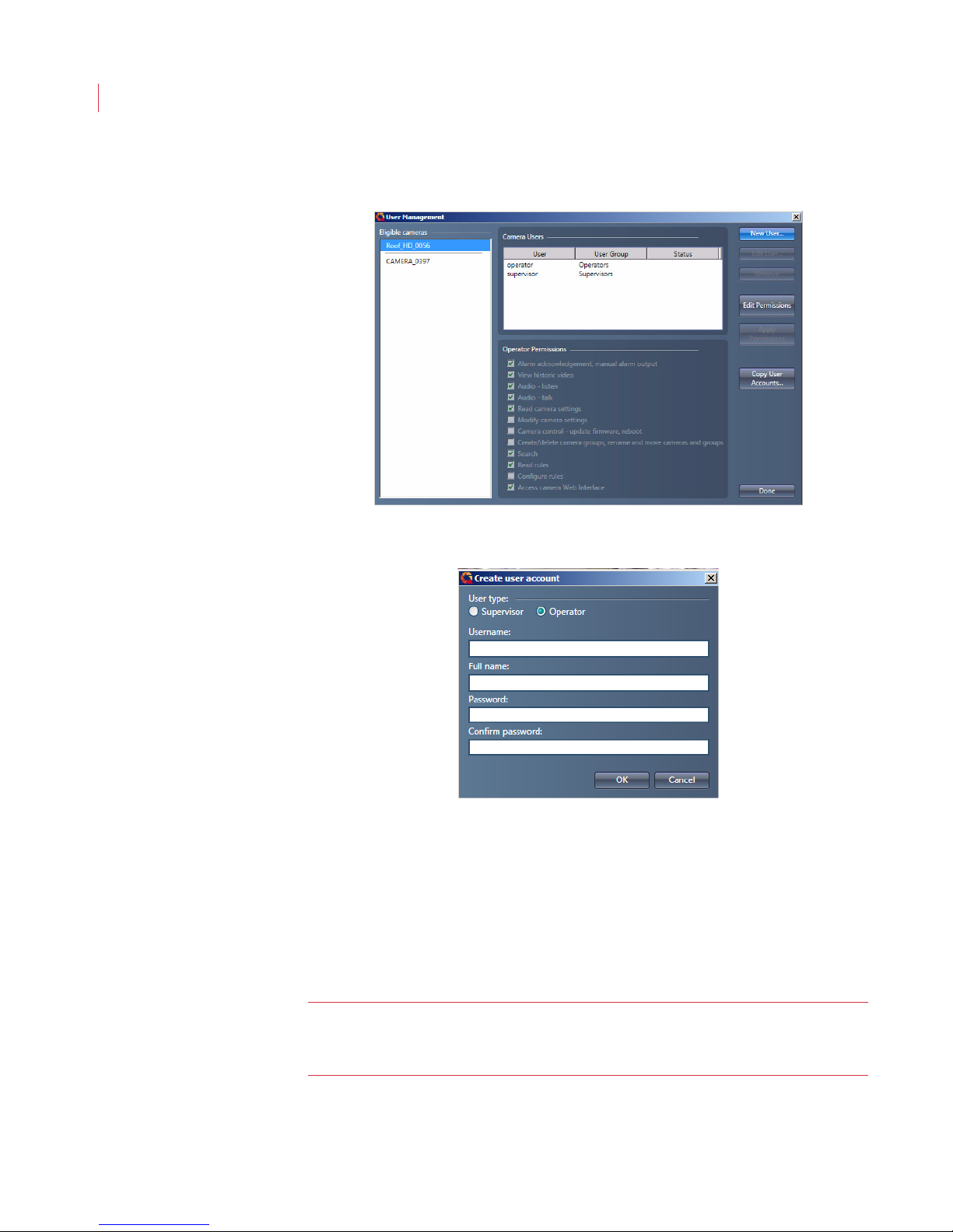
3. Select the cameras where you want to add a user.
Page 45
VideoIQ User Guide35
4. Click the New User button.
5. Assign a role to the user by selecting the Supervisor or Operator radio
button.
6. Enter a username.
7. Enter the full name of the user. This field is for your reference and does not
8. Enter a password for the user. The password must be a minimum of 4
9. Retype the password in the Confirm Password field.
10. Click OK.
Note: Once you have assigned a username to a user it cannot be changed. If
display in the View application.
characters, can include both numbers and letters, and is case sensitive.
you need to make a change the username, you will need to delete the
user, then recreate it.
Page 46
User Accounts
Copying User Accounts and Permissions From A Camera
You can copy the user account settings and permissions from one camera and
distribute them to other cameras.
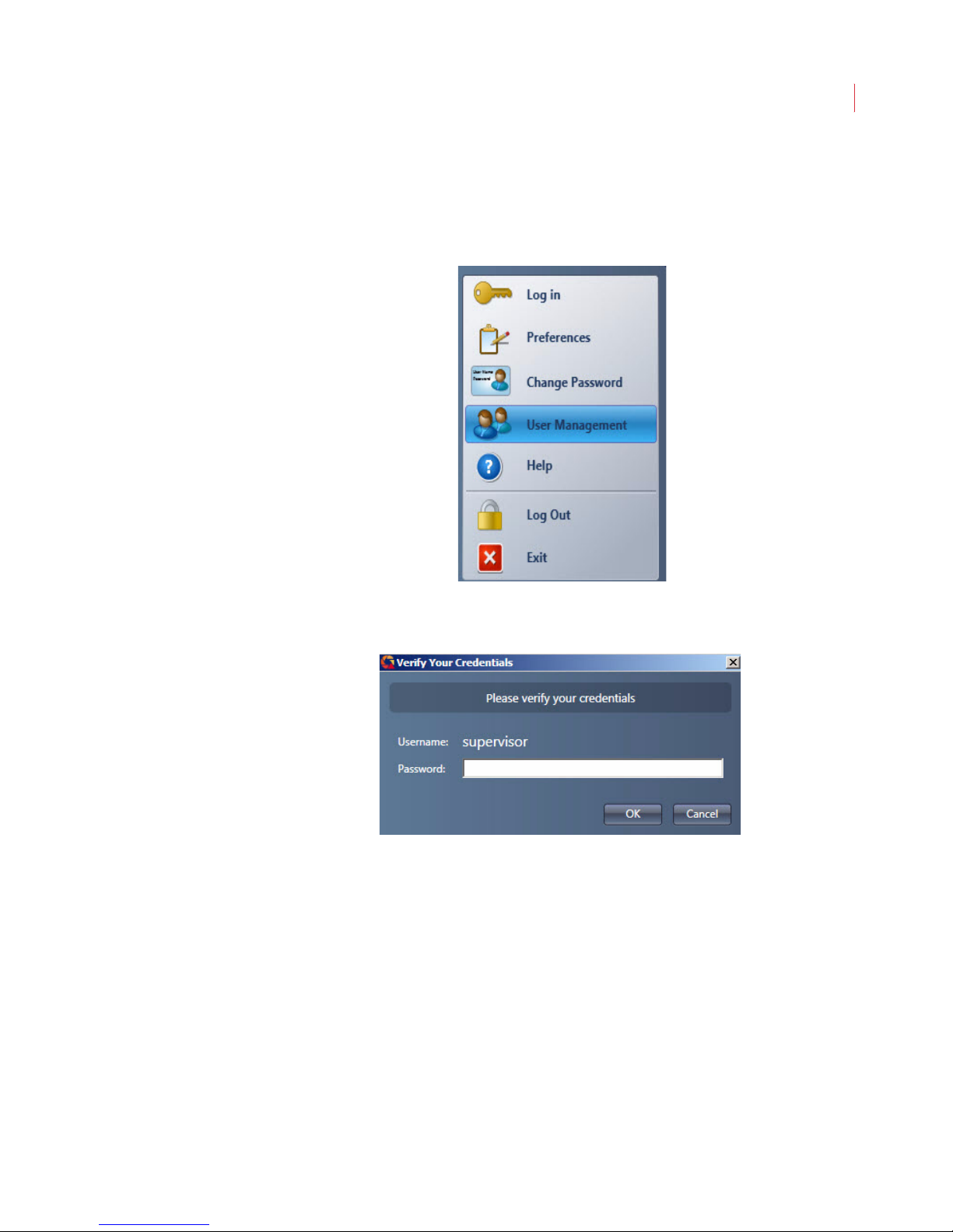
1. Click the VideoIQ button and choose User Management.
36
2. When the Verify Your Credentials dialog box displays enter your
Password and click OK.
3. When the User Management window appears, select the camera you
want to copy accounts from, then click the Copy User Accounts button.
Page 47
VideoIQ User Guide37
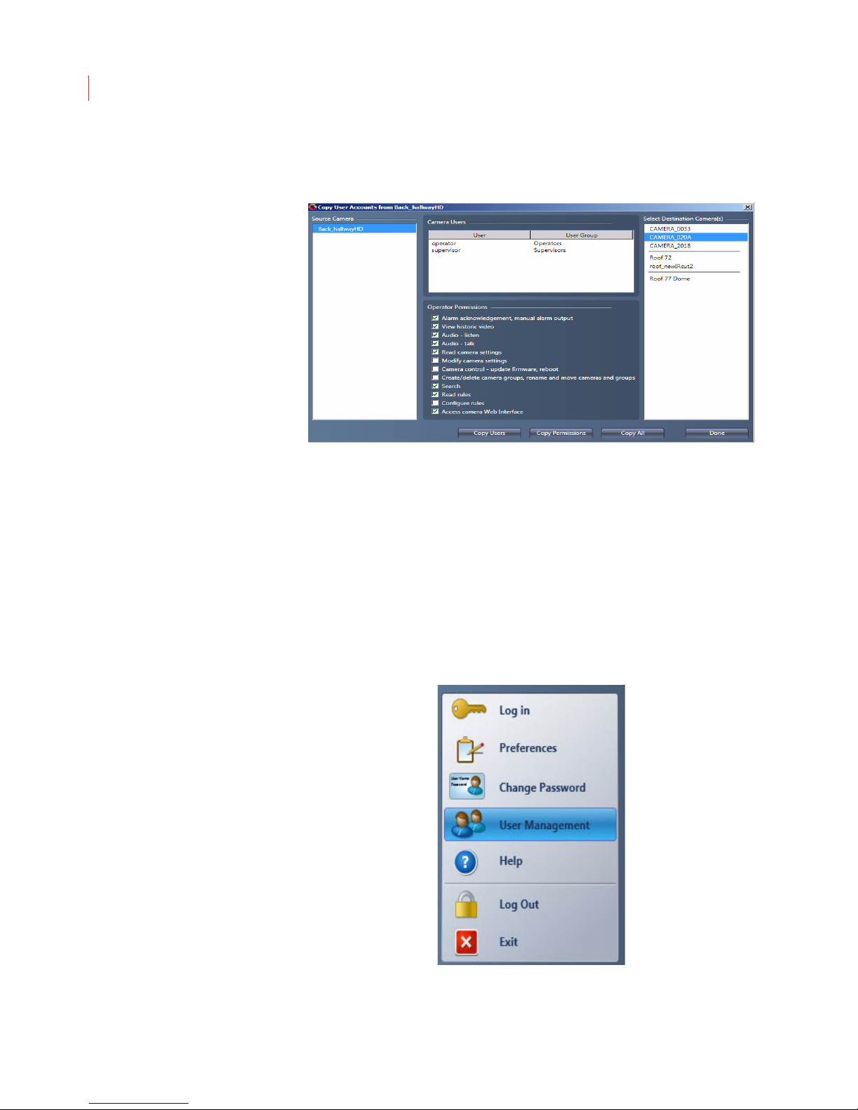
4. When the Copy User Accounts From window appears, select one or more
cameras from the Destination Cameras list, then click one of the following
buttons:.
Copy Users: Copies only the usernames and passwords of users
stored on the destination camera.
Copy Permissions: Copies only the permissions stored on the source
camera.
Copy All: Copies both the users and permissions stored on the source
camera.
5. Click Done.
Editing a User Account
Once you have created a user account you can easily edit it.
1. Click the VideoIQ button and select User Management.
Page 48
User Accounts
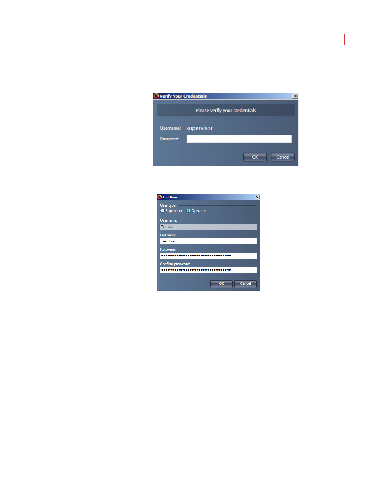
2. When the Verify Your Credentials dialog box displays enter your
Password and click OK.
3. The User Management dialog box displays.
4. Select a user and click the Edit User button.
38
5. Make changes to the User Type, Full name or Password fields.
6. Click OK.
Deleting a User Account
You can permanently delete any user account, except for the original Supervisor
account.
Page 49
VideoIQ User Guide39
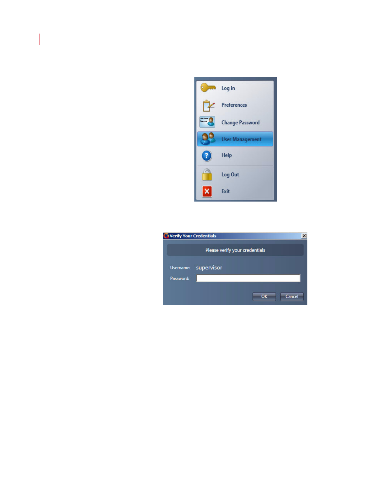
1. Click the VideoIQ button and select User Management.
2. When the Verify Your Credentials dialog box displays enter your
Password and click OK.
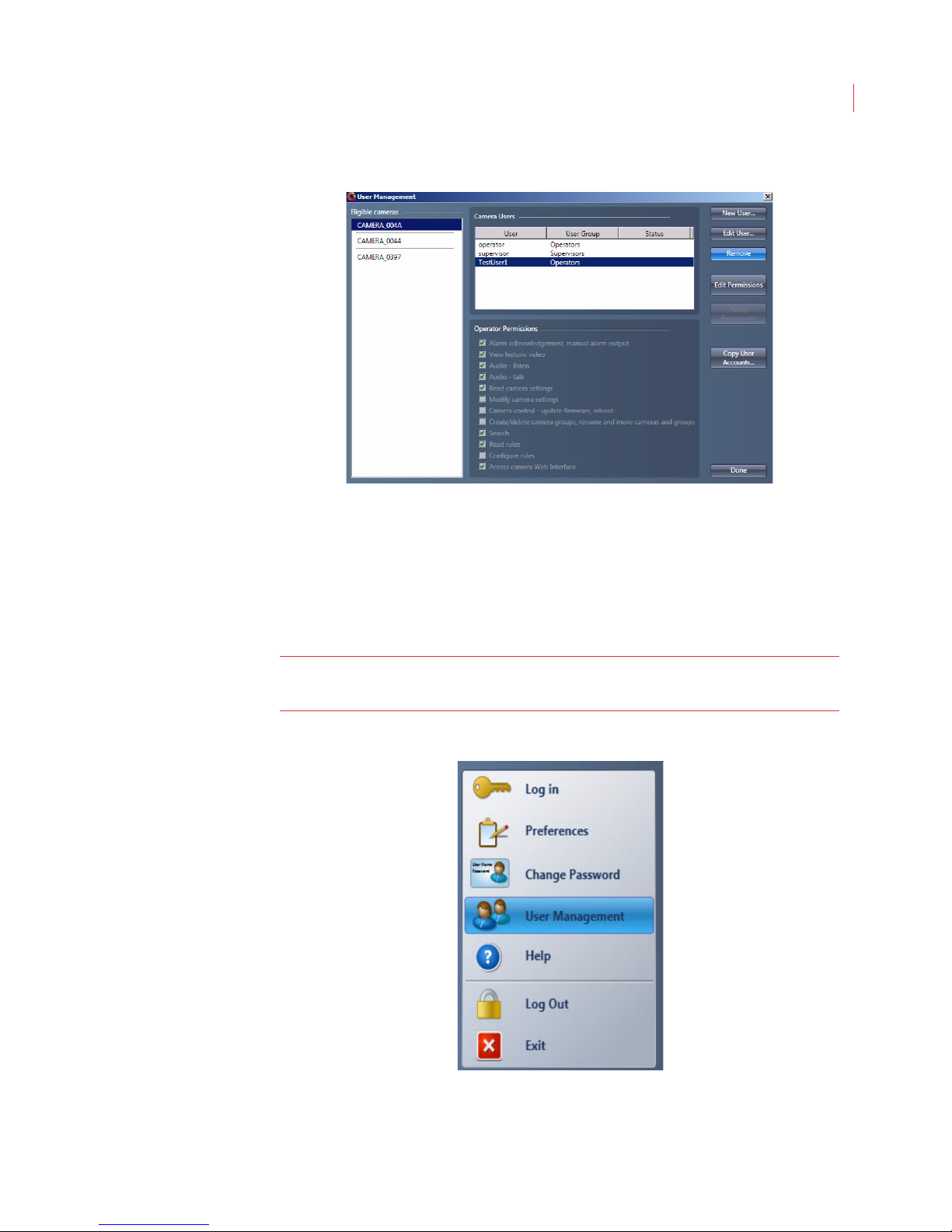
3. When the User Management box displays select the user you would like
to delete.
4. Click the Remove button.
Page 50
User Accounts
The user is permanently removed from the user list. You will not be prompted to
confirm the deletion.
40
Modifying User Permissions
Users with supervisor-level permissions can change the permissions that
Operators have to perform specific functions in View.
Note: When you make a change to the Operator Permissions it applies to all
users on the selected camera(s) with the Operator role.
1. Click the VideoIQ button and select User Management.
Page 51
VideoIQ User Guide41
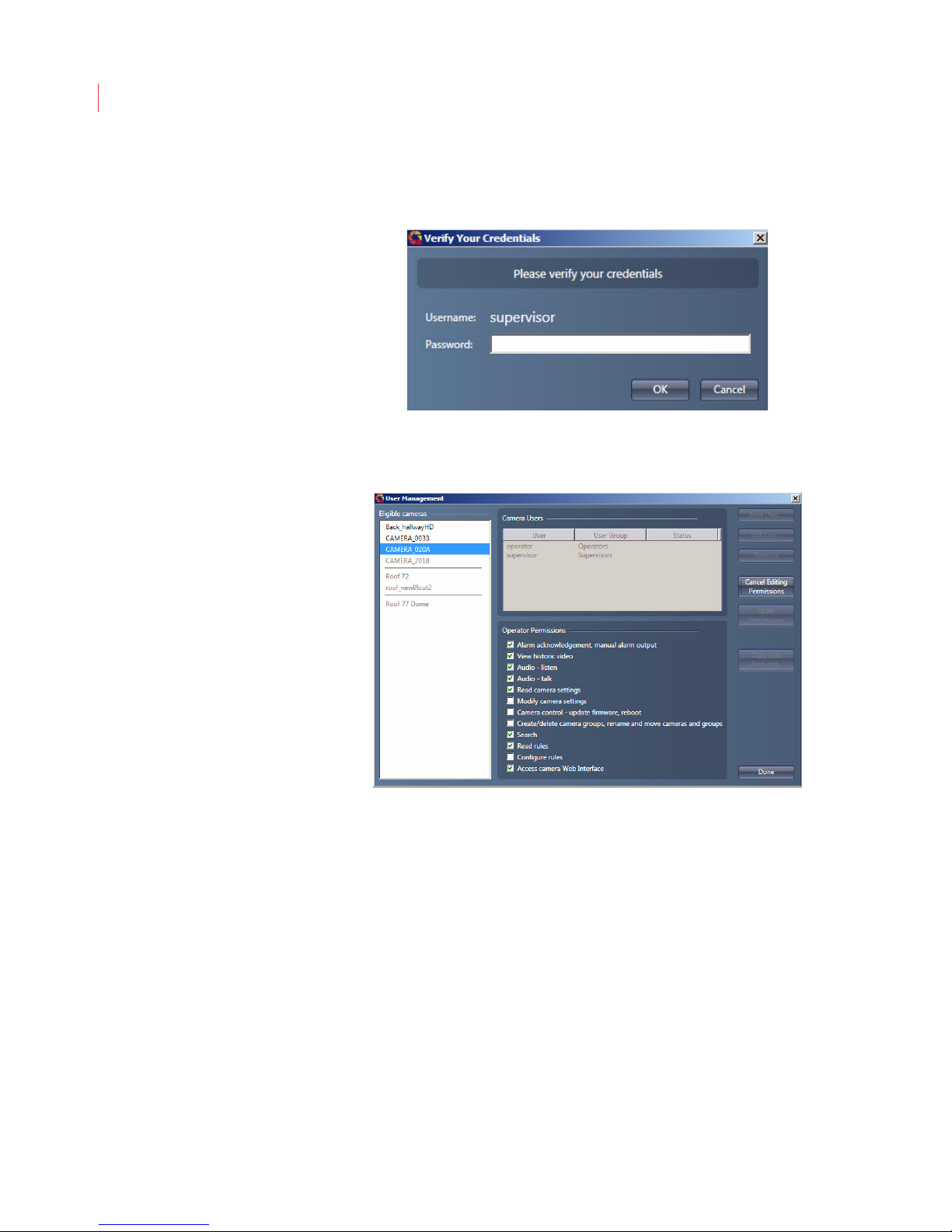
2. When the Verify Your Credentials dialog box displays enter your
Password and click OK.
3. When the User Management box displays, select the camera whose
permissions you want to edit, then click the Edit Permissions button.
Page 52
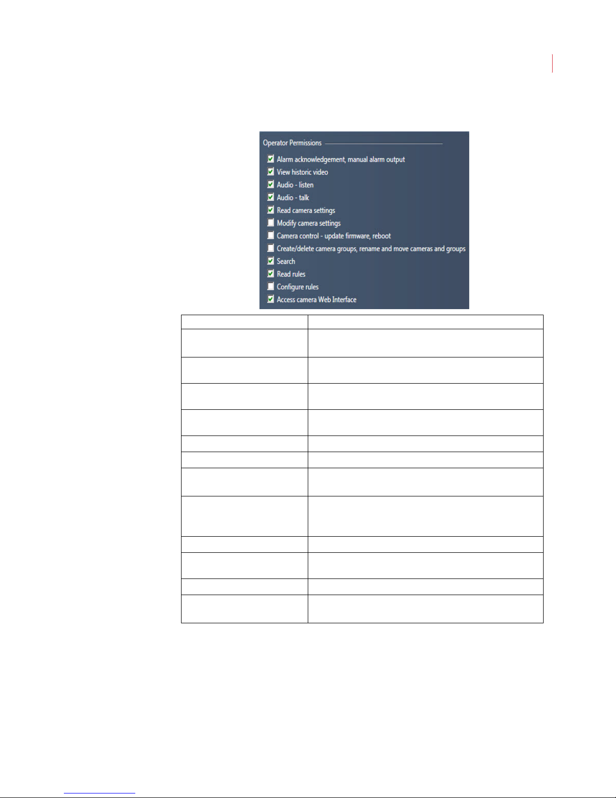
4. Select the permissions you want to give to all users with the role of
Operator.
Permission Description
Alarm acknowledgment,
manual alarm output
View historic video
Audio - listen
Audio - talk
Read camera settings
Modify camera settings
Camera Control - update
firmware, reboot
Create/delete camera
groups, rename and move
Allows the user to acknowledge alarms and to use the
Output button when enabled.
Allows the user to view historic video after performing a
search.
When a microphone is attached to the camera, allows the
user to listen to streaming audio at the PC.
When a microphone is attached to the PC, allows the user to
press the Talk button when enabled.
Allows the user to read, but not modify, all camera settings.
Allows the user to configure all camera settings.
Allow the user to update the firmware on a camera and to
reboot a camera.
Allows the user to create and delete camera groups; rename
a group, and move a camera into a group.
cameras and groups
Search
Read rules
Configure rules
Access camera web
Allows the user to perform a search on historic video.
Allows the user to read rules set up for each camera, but
does allow the user to modify the rules.
Allows the user to configure rules, ROIs, RODs and LOIs.
Allows the user to access the camera through a web browser.
interface
User Accounts
42
5. Click Done.
Page 53
8
Configuring View Preferences
This chapter describes:
Configuring View Preferences
Configuring View Preferences
You can configure the alarm sounds, storage and video settings on all cameras
under the Preferences menu. To access these settings click the VideoIQ button
and choose Preferences:
Page 54
VideoIQ User Guide44
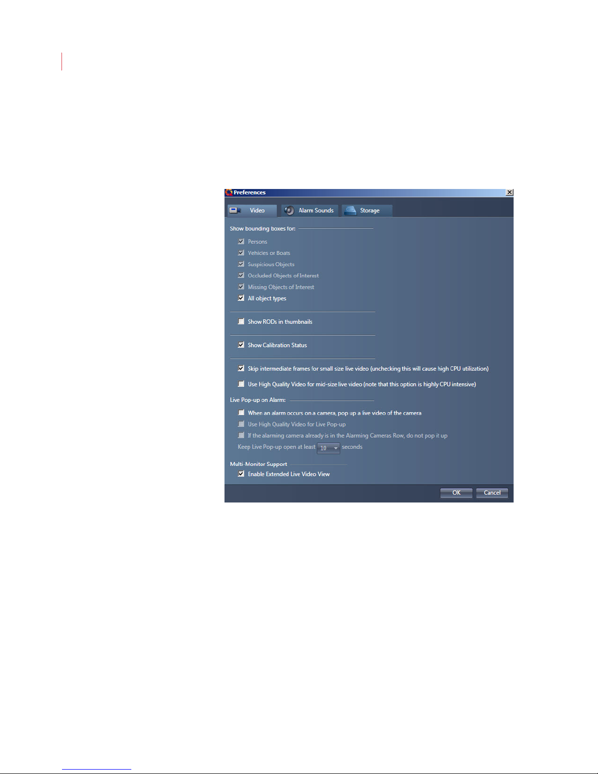
Video
Use the Video tab to determine which types of objects you want to see bounding
boxes for in View; to indicate if you want to see regions of disinterest (RODs) in
thumbnail clips; to indicate if you want to show calibration status, and to enable
live pop-up alarms and multi-monitor support.
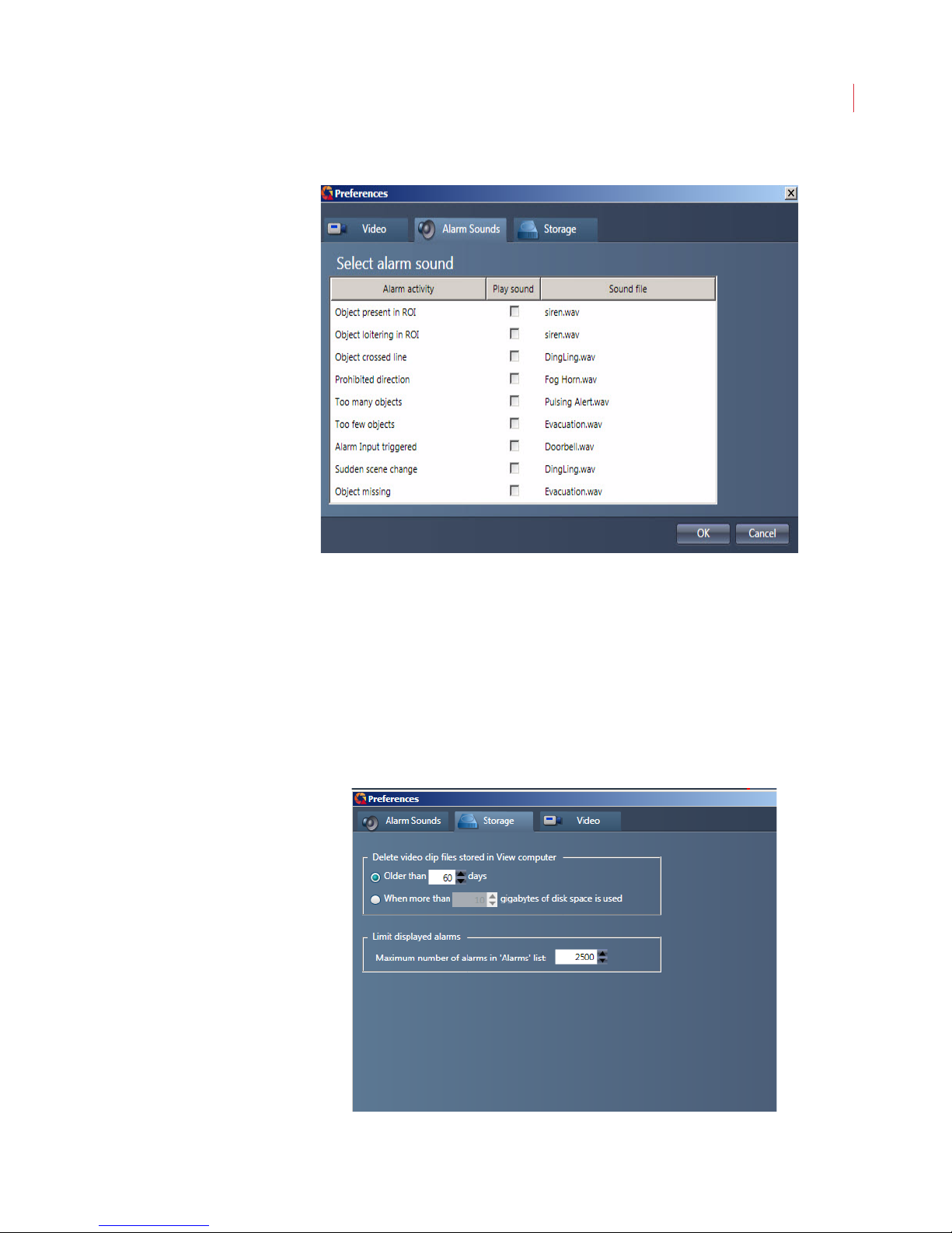
Alarm Sounds
On the Alarms tab you can choose to have your PC play sound when a rule is
violated. By default this setting is turned off; to enable it, check Play Sound.
To change the sound file:
1. Highlight the alarm activity.
2. Click the Browse button.
3. Select a new sound file; click Open.
4. Click OK.
Page 55
Configuring View Preferences
45
When an alarm is sounding you can stop it by pressing any key on your keyboard
or by acknowledging the alarm via the Alarms screen.
Storage
Use the Storage tab to specify if you want video clips stored on your PC deleted
based on the age of the clip, or when a predetermined amount of storage has
been used. This will not affect the storage of videos in your iCVR.
You can also use this tab to configure the number of alarms you want displayed
on the Alarms page. The maximum number of alarms that can be displayed is
10,000.
Page 56

9
Administering Cameras
This chapter describes:
Camera List Icons
Camera List Toolbar
Discovering Cameras
Adding a Camera
Editing Connections
Exporting and Importing the Camera Tree
Renaming a Camera
Creating a Camera Group
Deleting a Camera Group
Displaying Camera Information
Deleting a Camera from the Camera List
Upgrading Firmware
Upgrading Multiple iCVRs
Saving Camera Settings to Backup
Restoring Camera Settings from Backup
Restoring Camera Settings to Default Values
Configuring Basic N Settings
Configuring Advanced Network Settings
Configuring Video Settings
Configuring Audio Input and Output
Configuring Encoder Settings
Configuring PTZ Settings
Configuring Input/Output Settings
Configuring Storage and Compression Settings
Configuring Date and Time Settings
Configuring Analytics Settings
Configuring Email Settings
Configuring FTP/HTTP
Page 57
VideoIQ User Guide47
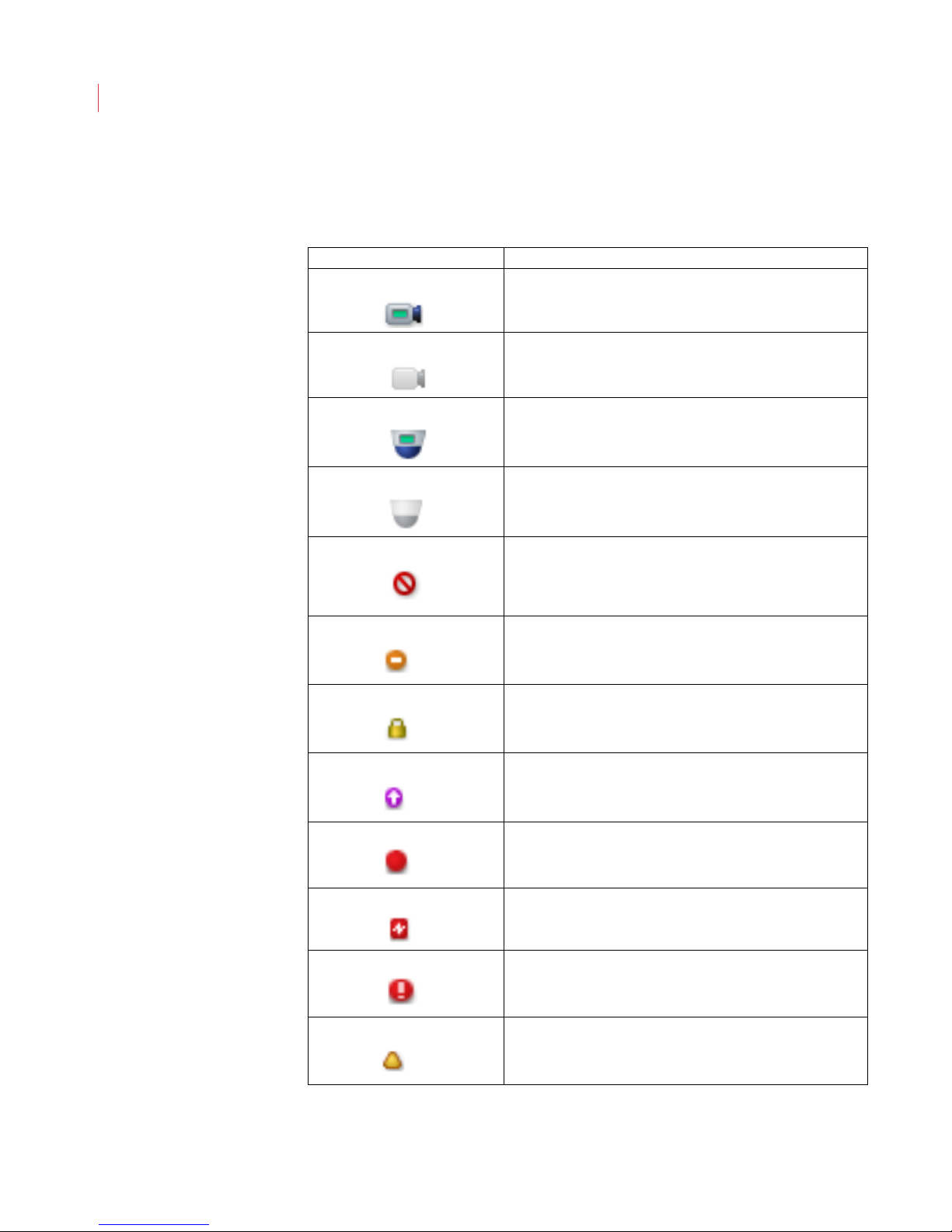
Camera List Icons
The icons displayed in the camera list identify the current state of each camera.
Camera Icon Description
Camera is connected.
Camera is not accessible
PTZ camera is connected.
PTZ camera is disconnected and is not accessible
Camera is disconnected.
When this icon is overlayed with the triangle icon it indicates
the version of View installed is incompatible with the camera
and should be upgraded.
Camera is online but has the maximum number of 3
connections. Camera cannot accept more connections.
Incorrect login.
The firmware on the camera is obsolete.
A rule violation has occurred
Encoder signal loss.
System alarm.
Camera is not functioning at full capacity because it is still
initializing or it is upgrading its database. Also indicates a
hard disk failure.
Page 58
A dministering Cameras
Camera Shortcuts Toolbar
The camera shortcuts toolbar is located above the camera tree and provides
quick access to the menus for camera settings and functionality.
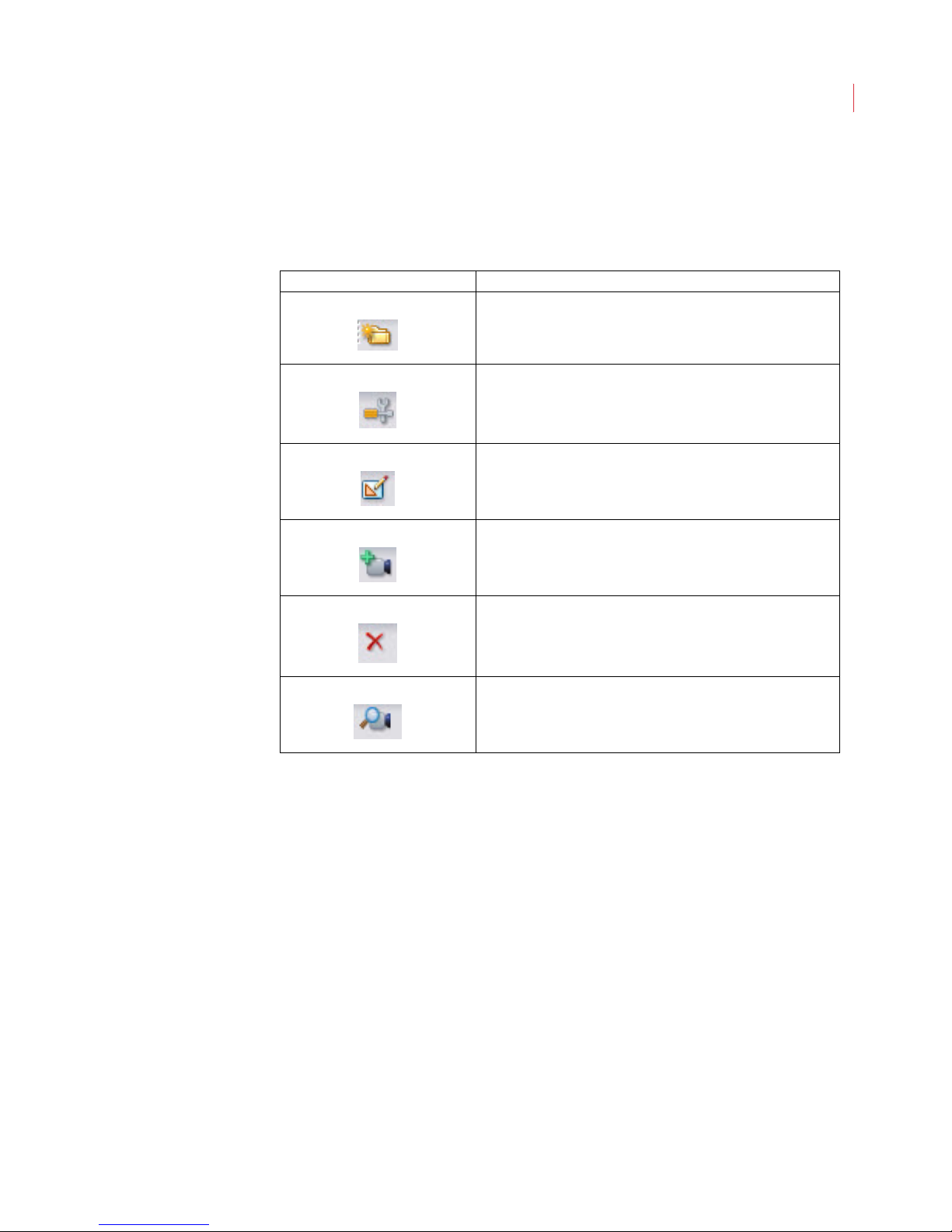
Camera Icon Description
The Create New Group button lets you add a camera group
to your camera tree.
The Configure Camera Settings button allows you to
configure network and port, Encoder, storage and
compression, analytics as well as date and time settings,
The Edit Regions button lets you configure and edit regions
and lines of interest.
48
The Add Camera button allows you to manually add a
camera to the camera tree.
The Delete button is used to delete a camera or camera
group from the camera list. You will not be prompted to
confirm your deletion.
The Discover Camera button automatically discovers
cameras and adds them to your camera tree.
Discovering Cameras
After your PC is set for automatic addressing, and you have started and logged
into View, click the Auto-Discover button in the Camera Shortcut toolbar. If your
iCVR and View are on the same subnet, View will automatically find your iCVRs
and add them to the camera tree.
Auto-discovery will not work across a WAN, or if you’re using a VPN connection.
For both of these scenarios cameras will need to be added manually.
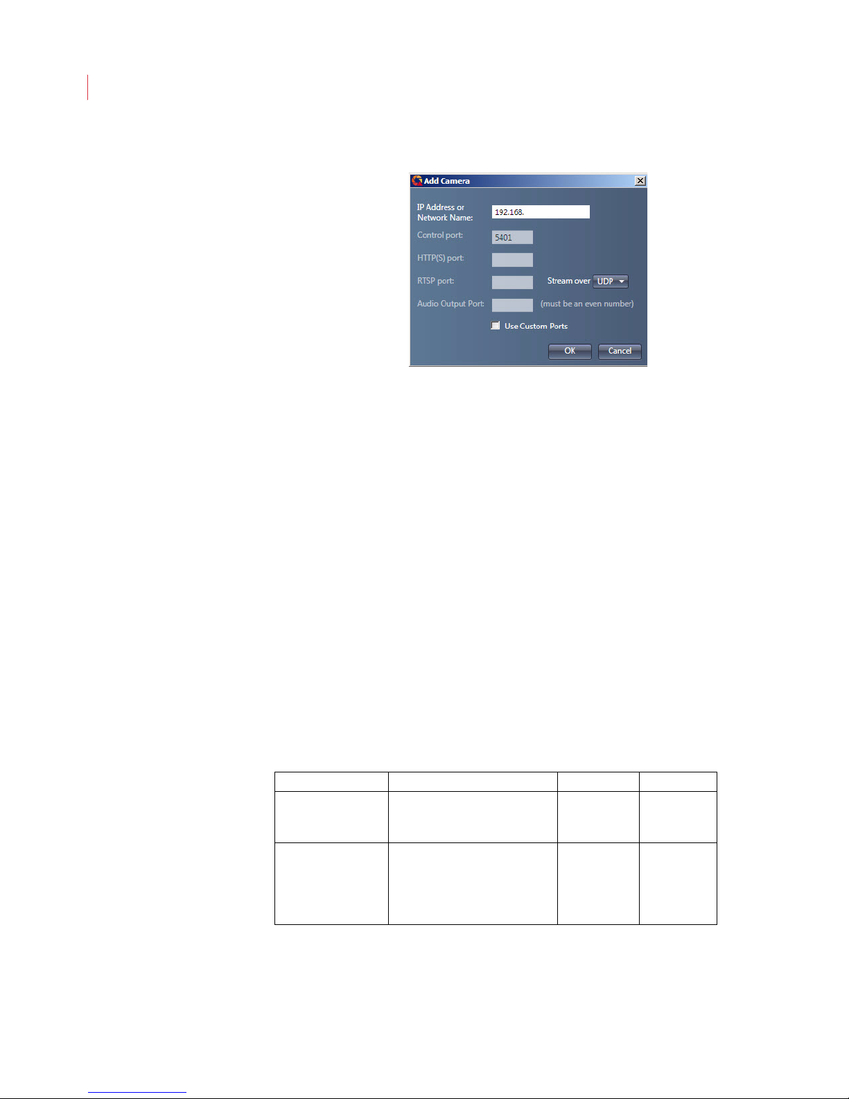
Adding a Camera
If View does not automatically discover your camera, you will need to add it
manually:
1. Click the Add Camera button in the Camera Shortcut toolbar.
2. Enter the IP address or network name of the camera.
Page 59
VideoIQ User Guide49
3. Select an option from the Stream Over drop-down menu:
UDP: This is the most bandwidth-efficient selection. However, this
protocol is not allowed to pass through all firewalls. If you’re having
trouble seeing live streaming video, select either TCP or HTTP(S).
TCP: Encapsulates the RTP traffic into standard TCP packets and
streams it to the client. Select this protocol if your firewall will not pass
UDP traffic.
HTTP(S): The least bandwidth-efficient selection. This encapsulates RTP
and RTSP into HTTP transfers. The advantage of this streaming method
is that it uses one port for
Web browsing to the camera
Video streaming
Audio streaming
When you use this streaming protocol, separate ports for RTSP and
Audio are no longer required.
When using port mapping on a router with an externally accessible IP
address, click the Use Custom Ports checkbox and enter the port
numbers in the Control Port, HTTP(S) Port, RTSP Port, and Audio Output
Port fields.
Port Function Default Value Type
Control Port Secure communication
between View and the iCVR
takes place through this port
HTTPS Port Encrypted file transfer and
web access to the camera
take place through this port.
Choose to run the camera over
HTTPS or HTTP
5401 TCP
443 TCP
Page 60
Administering Cameras
Port Function Default Value Type
HTTP Port File transfer and web access
to the camera take place
through this port. Choose to
run the camera over HTTP or
HTTPS.
80 TCP
50
RTSP Port Data that controls the video
stream goes through this port.
Audio Output Port When a speaker is attached to
the iCVR, audio transmits
through this port.
554 UDP and TCP
20022 UDP and TCP
Note: The port number after the RTSP port is reserved by the camera for
internal use. When configuring View, one empty port must be allowed
between the RTSP and the Audio Output port.
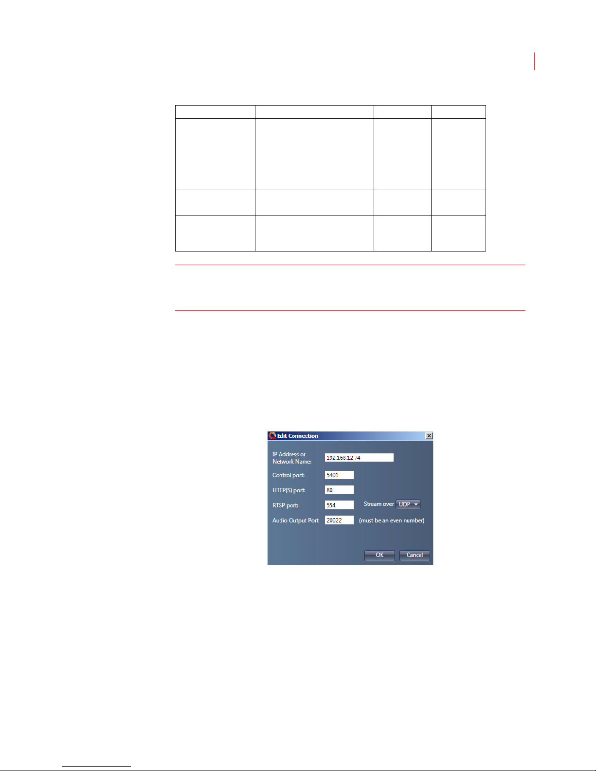
Edit Connections
You can change the port numbers or streaming protocol once a camera has been
added to the camera tree:
1. Select the camera in the camera tree.
2. Right-click on the camera and select Edit Connections.
Exporting and Importing the Camera Tree
When you have multiple PC’s running View you can export the camera tree from
one instance of View and import it into subsequent instances of View. Exporting
the camera tree exports the cameras and/or camera groups, and all camera
connection information to a file.
To export the camera tree:
1. At the top of the camera tree right-click on VideoIQ.
Page 61

VideoIQ User Guide51
2. Select Export Camera Tree...
3. The Save As dialog box appears. Navigate to the location on your PC or
network where the file will be saved and click Save.
4. The Exporting Camera Tree... status bar appears.
When the export finishes the status bar closes automatically.
Page 62
Administering Cameras
5. The camera tree settings are saved as an .xml file that can be imported into
View.
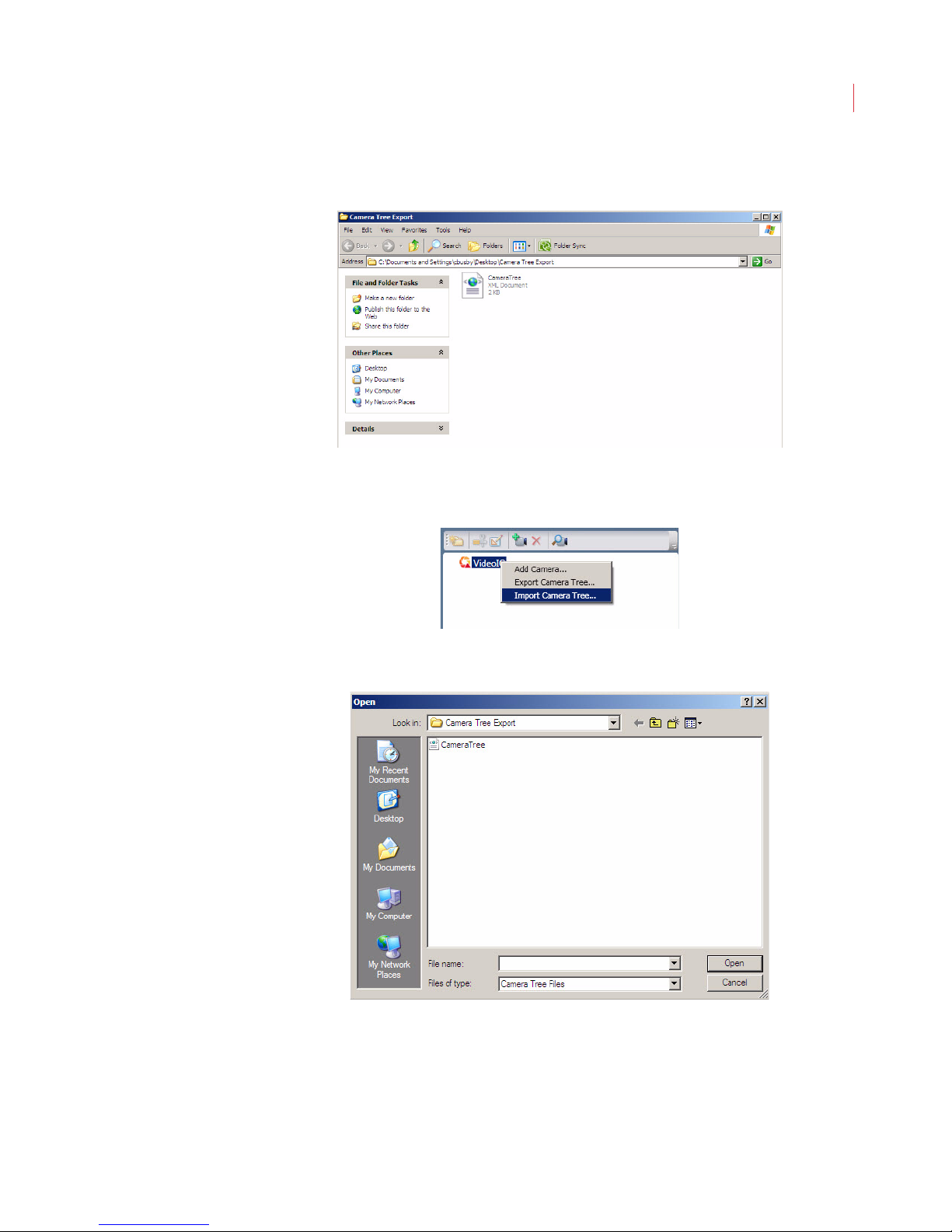
To import camera tree settings:
1. At the top of the camera tree, right-click on VideoIQ and select Import
Camera Tree...
52
2. The Open dialog box appears. Select the .xml file you exported using the
steps above and click Open.
Page 63
VideoIQ User Guide53
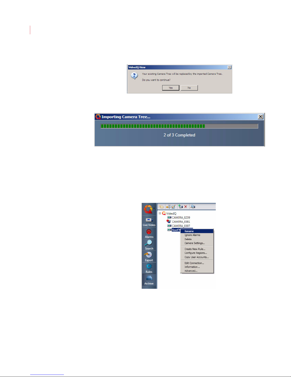
3. A dialog box appears to warn you that any existing camera tree information
will be overwritten with the new file. Click Yes to proceed with the import.
4. The Importing Camera Tree... status bar appears. The status bar disappears
once the import process is complete.
Once the camera tree has been imported the cameras will automatically try to
reconnect. If connection cannot be established a warning message displays in
View.
Renaming a Camera
To rename a camera:
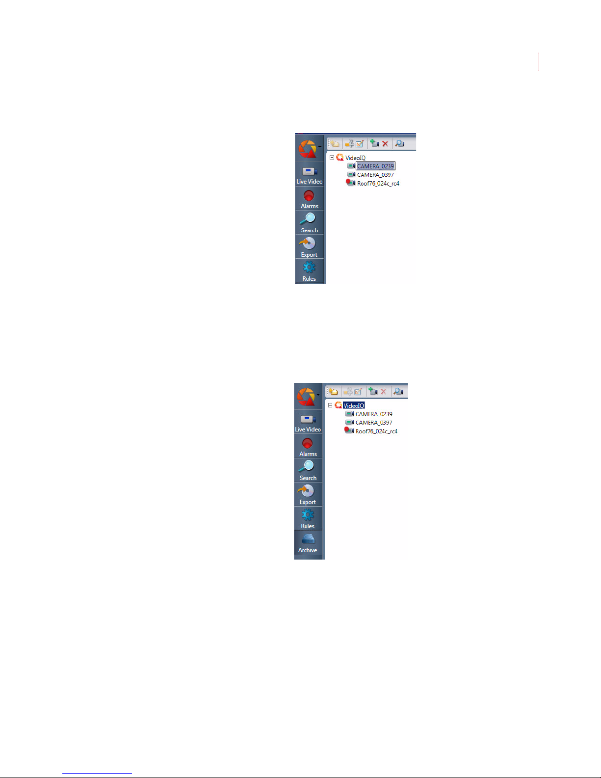
1. Right-click a camera and choose Rename.
Page 64
Administering Cameras
2. When the current camera name is highlighted, enter the new name for the
camera.
Renaming a camera changes the name for all users logged into View.
Creating a Camera Group
54
You can create camera groups to organize your cameras or to apply the same
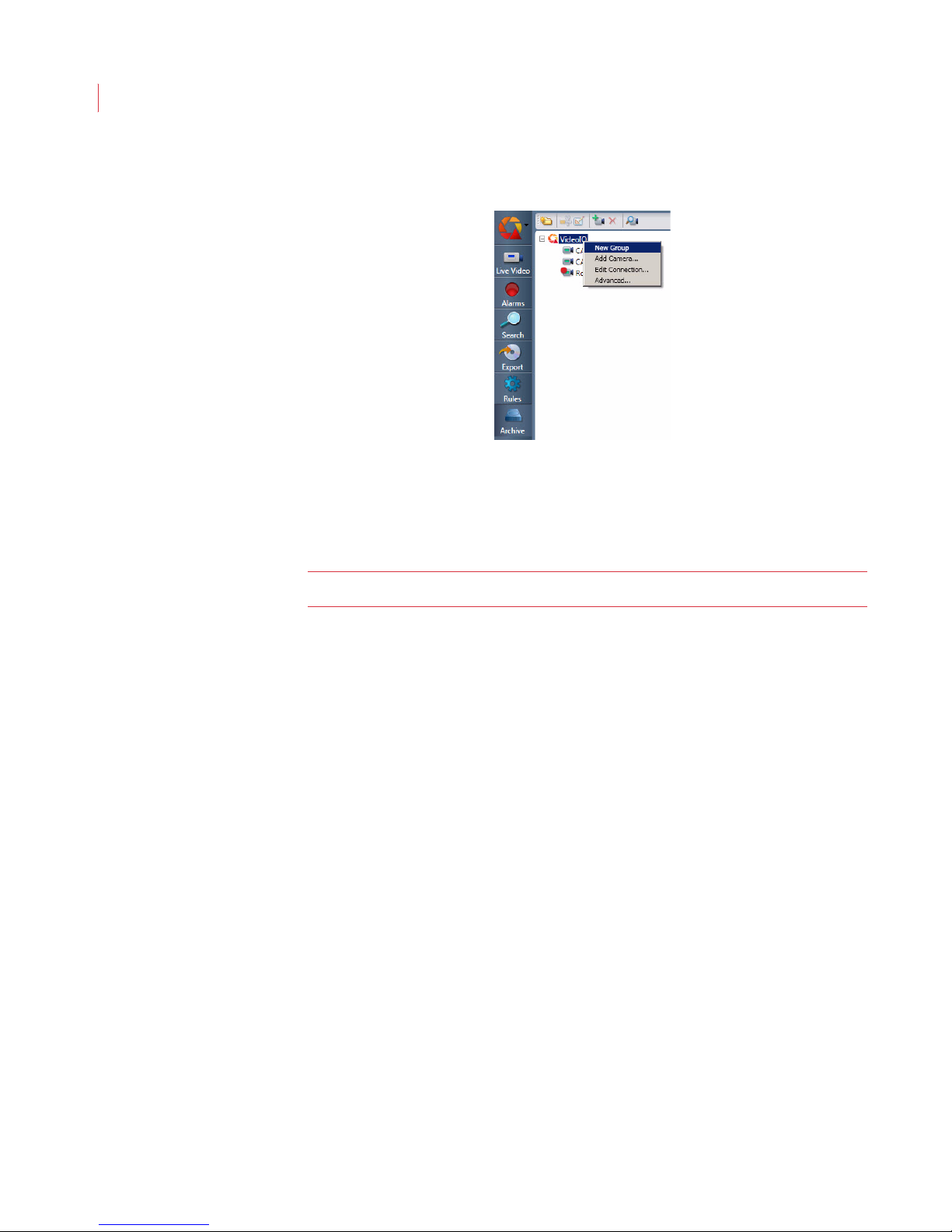
configuration to all cameras in the group. To create a camera group:
1. Click VideoIQ in the camera tree.
Page 65
VideoIQ User Guide55
2. When the New Group icon appears, right-click on it and choose Rename to
assign it a name.
3. When the group name is highlighted, enter the new name and press Enter.
4. To add cameras to the camera group, drag camera icons into the camera
group folder.
The camera group displays to all users logged into View.
Note: A camera can belong to only one camera group.
Deleting a Camera Group
Deleting a camera group removes only the group folder and does not delete the
cameras from the camera tree. To delete a group:
1. Highlight the group you would like to delete.
2. Right-click on the group and choose Delete.
Displaying Camera Information
To display the current settings for a camera:
Page 66
Administering Cameras
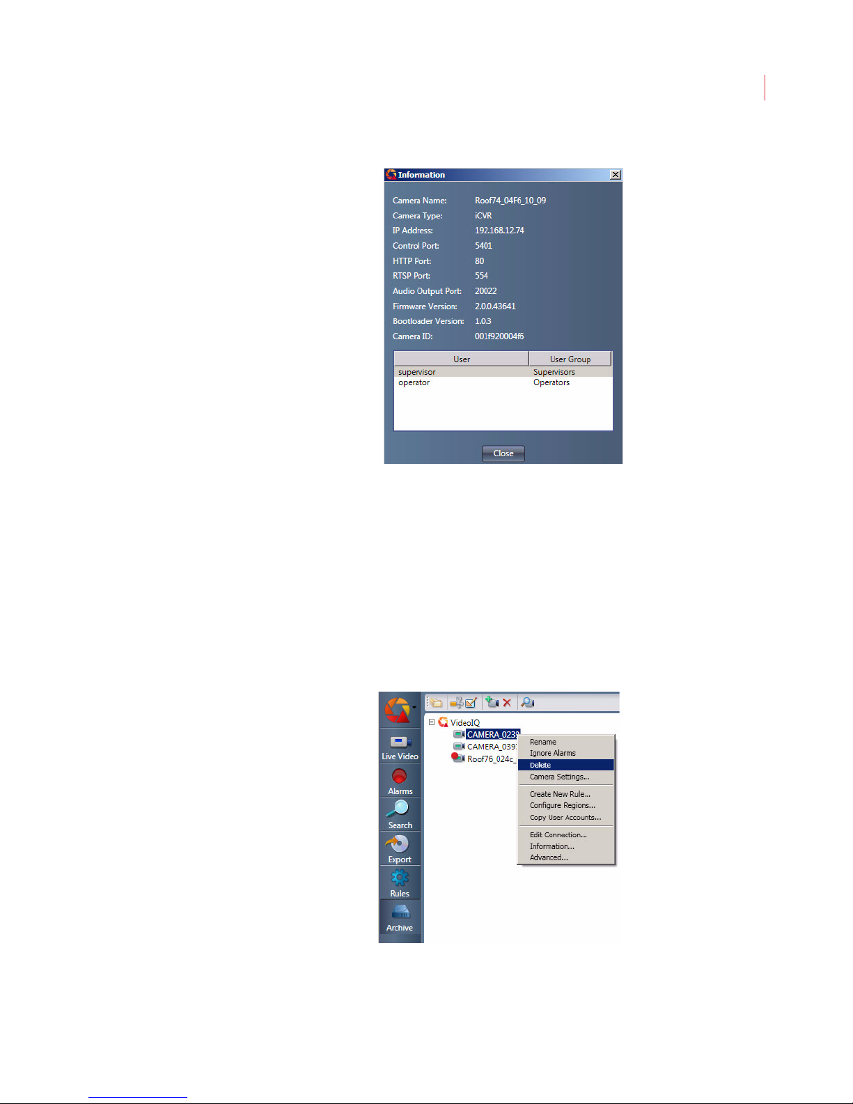
1. Right-click the camera and choose Information.
The Camera Information window displays the name, IP address, port settings,
firmware version, and user list for the selected camera.
56
2. Click Close when you are finished.
Deleting a Camera From the Camera List
To delete a camera from the camera list:
1. Select the camera;
Alternatively you can right-click on the camera and choose Delete:
2. Confirm the deletion.
Once you’ve deleted a camera it won’t be available again until you add it or it’s
auto-discovered.
Page 67
VideoIQ User Guide57
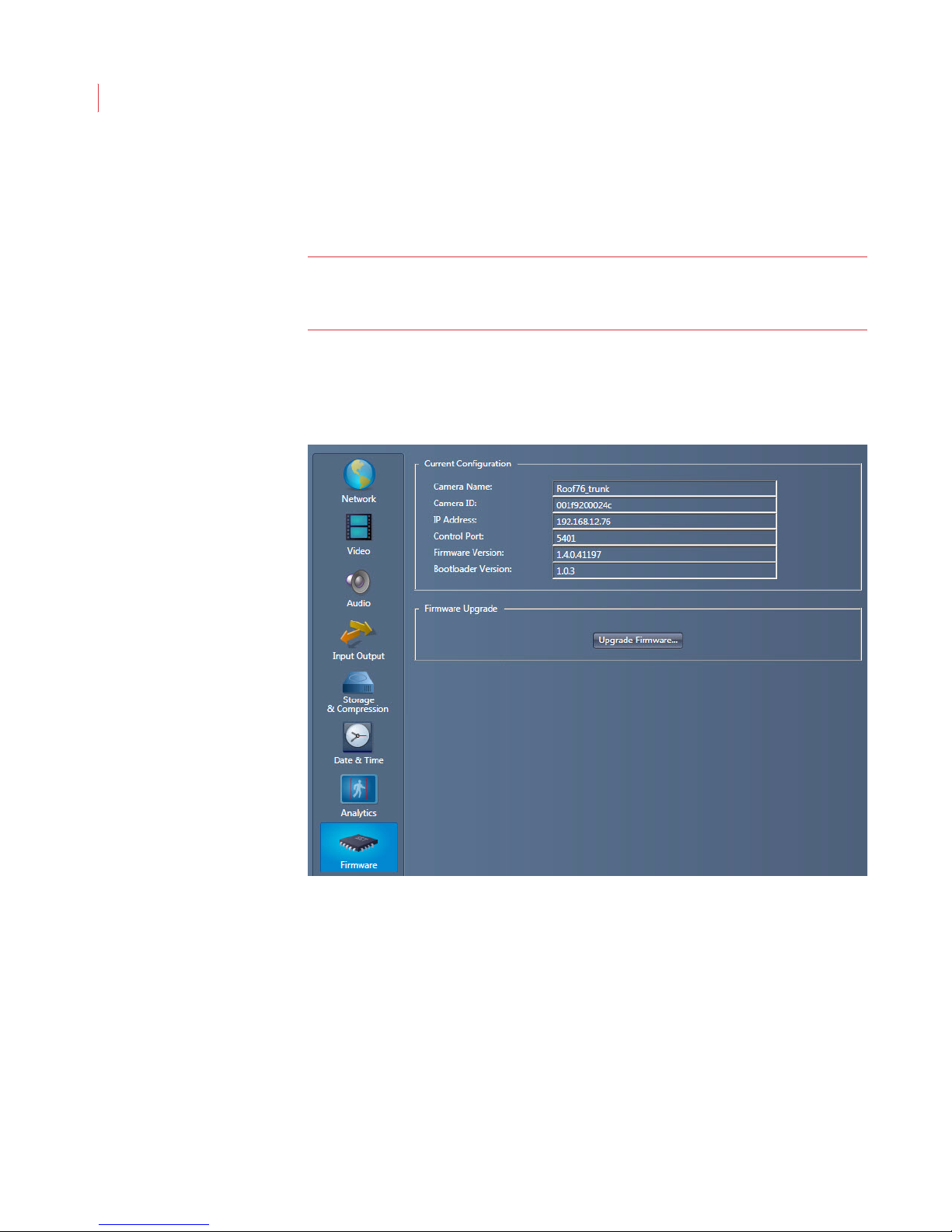
Upgrading Firmware
The Firmware Settings window shows the current configuration for your camera,
and lets you upgrade the firmware on your iCVR.
Note: Firmware upgrades should only be performed by advanced users. If you
need assistance while performing an upgrade please contact VideoIQ
Technical Support
1. Contact VideoIQ Technical Support for the link to the download location of the
file needed for upgrading the camera firmware.
2. When the Configure Camera window opens, click Firmware.
The Firmware Settings window displays.
3. Click the Upgrade Firmware button.
4. Confirm that you want to upgrade the firmware in your iCVR.
Page 68
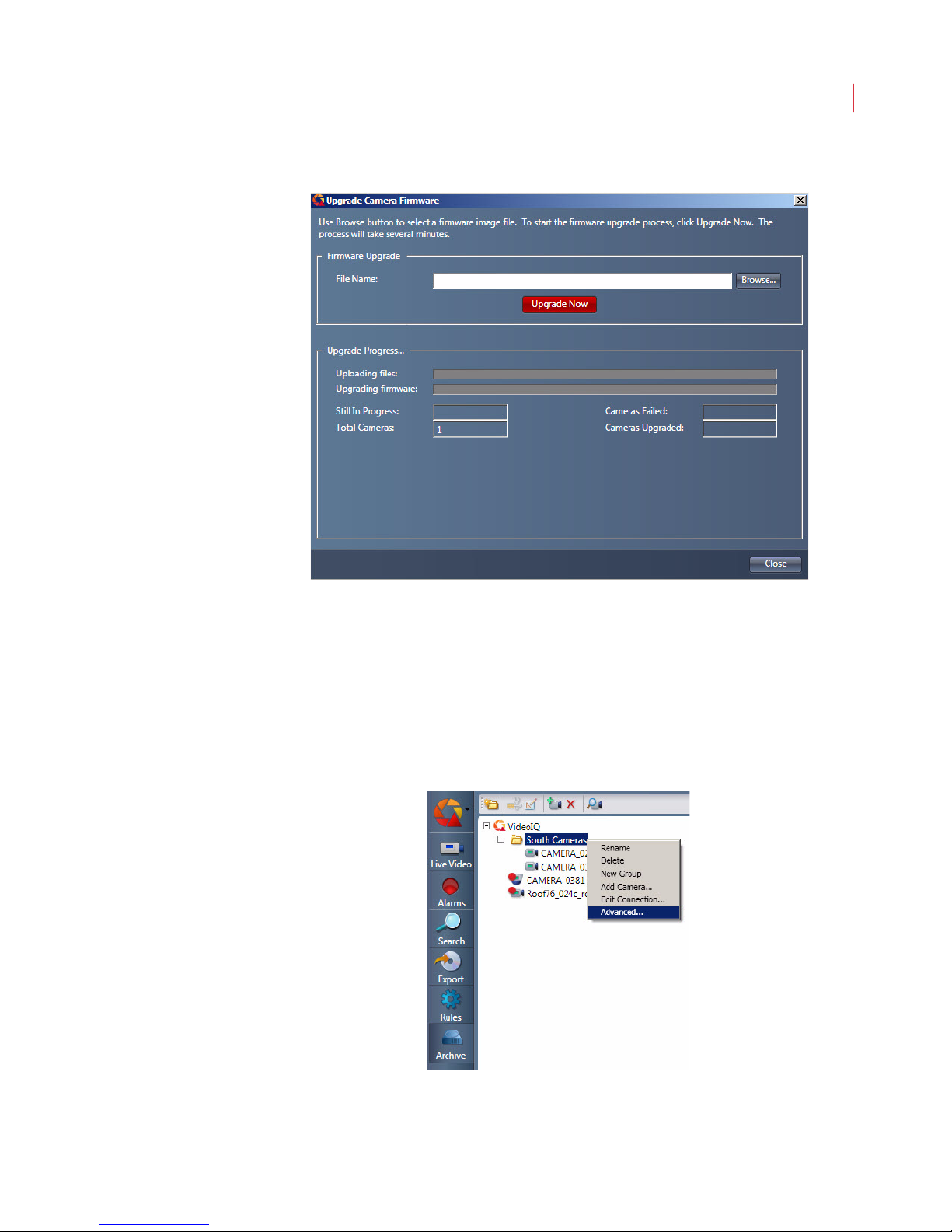
5. The Upgrade Camera Firmware page displays.
Administering Cameras
58
6. Use the Browse button to navigate to the directory where the upgrade file is
stored on your local computer.
7. Click the Upgrade Now button.
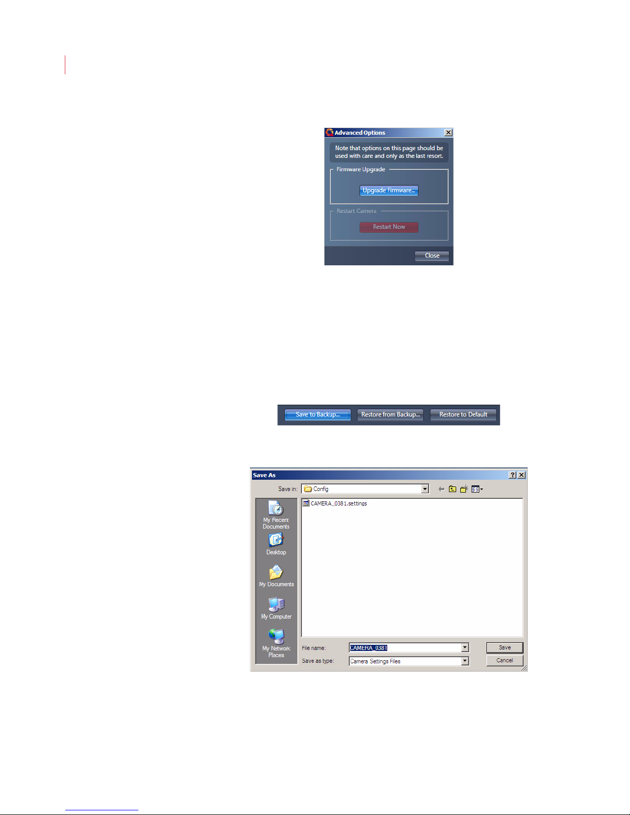
Upgrading Multiple iCVRs
You can upgrade multiple iCVRs simultaneously when they are in a camera
group:
1. Right-click on the camera group and select Advanced.
Page 69
VideoIQ User Guide59
2. Click the Firmware button.
3. Follow steps 4-7 of the preceeding section.
Saving Camera Settings to Backup
After you have configured the settings in your iCVR, you can archive them to a
backup file. To save your camera settings:
1. Select a camera from the camera tree and click the Camera Settings button.
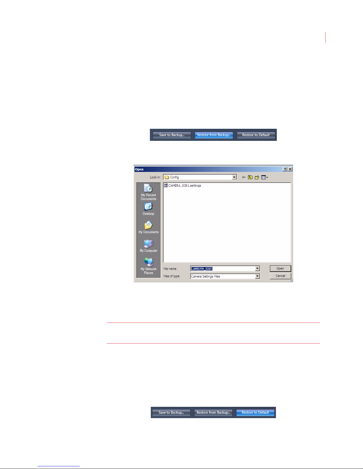
2. When the Configure Camera window appears, click the Save to Backup
button at the bottom of the screen.
3. When the Save As window appears, specify the destination directory and
name for the backup file.
4. Click Save.
By default, camera settings files are saved in the C:\VideoIQ
data\Config directory with a .settings file suffix.
Page 70
Administering Cameras
Restoring Camera Settings from Backup
You can restore the settings for an iCVR from a backup file if you accidentally
misconfigure it.
To restore camera settings from an archive file:
1. Select a camera from the camera tree and click the Camera Settings button.
2. When the Configure Camera window appears, click the Restore from
Backup button at the bottom of the screen.
3. When the Open window appears, navigate to the source directory and select
the backup file you want to use.
60
By default, camera settings files are saved in the C:\VideoIQ
data\Config directory with a .settings file suffix.
4. Click Open.
Note: Restoring camera settings will cause the camera to automatically reboot.
Restoring Camera Settings to Default Values
To restore camera settings to their default values:
1. Select a camera from the camera tree and click the Camera Settings button.
2. When the Configure Camera window appears, click Restore to Default
button located at the bottom of the screen.
It will be disconnected while rebooting.
Page 71
VideoIQ User Guide61
The camera settings are immediately reset to their default values and the camera
restarts automatically. The camera may take several minutes to become active in
the camera list after it restarts.
Using the Force Login
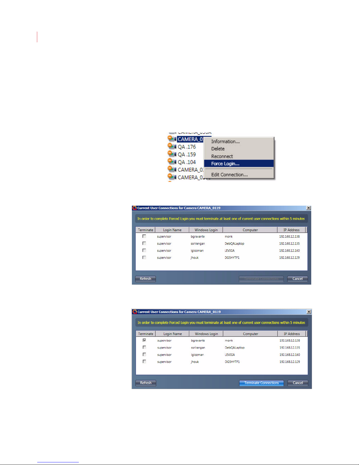
When the login limit has been reached on a camera a supervisor can login with
Force Login and disconnect one or more users.
1. Right-click on the camera in the camera tree and choose Force Login.
2. The Current User Connections dialog displays, listing the users currently
logged into the camera.
3. Check the box next to user(s) you want to disconnect and click Terminate
Reviewing User Connections
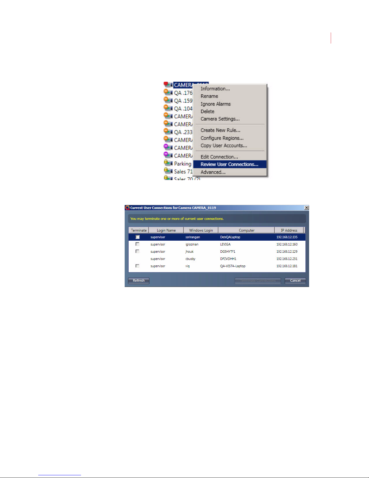
The Review User Connections feature lets a supervisor view who is logged into a
camera.
Connection.
Page 72
Administering Cameras
1. Right-click on the camera in the camera tree and choose Review User
Connections.
2. The Current User Connections dialog displays, listing the users currently
logged into the camera.
62
To disconnect one or more users check the box next to the name(s), then click the
Terminate Connections button.
Configuring Camera Settings
To configure camera settings, select the camera or group from the list and click
the Camera Settings button in the toolbar.
Alternatively, you can right-click on the camera and choose Camera Settings.
Page 73
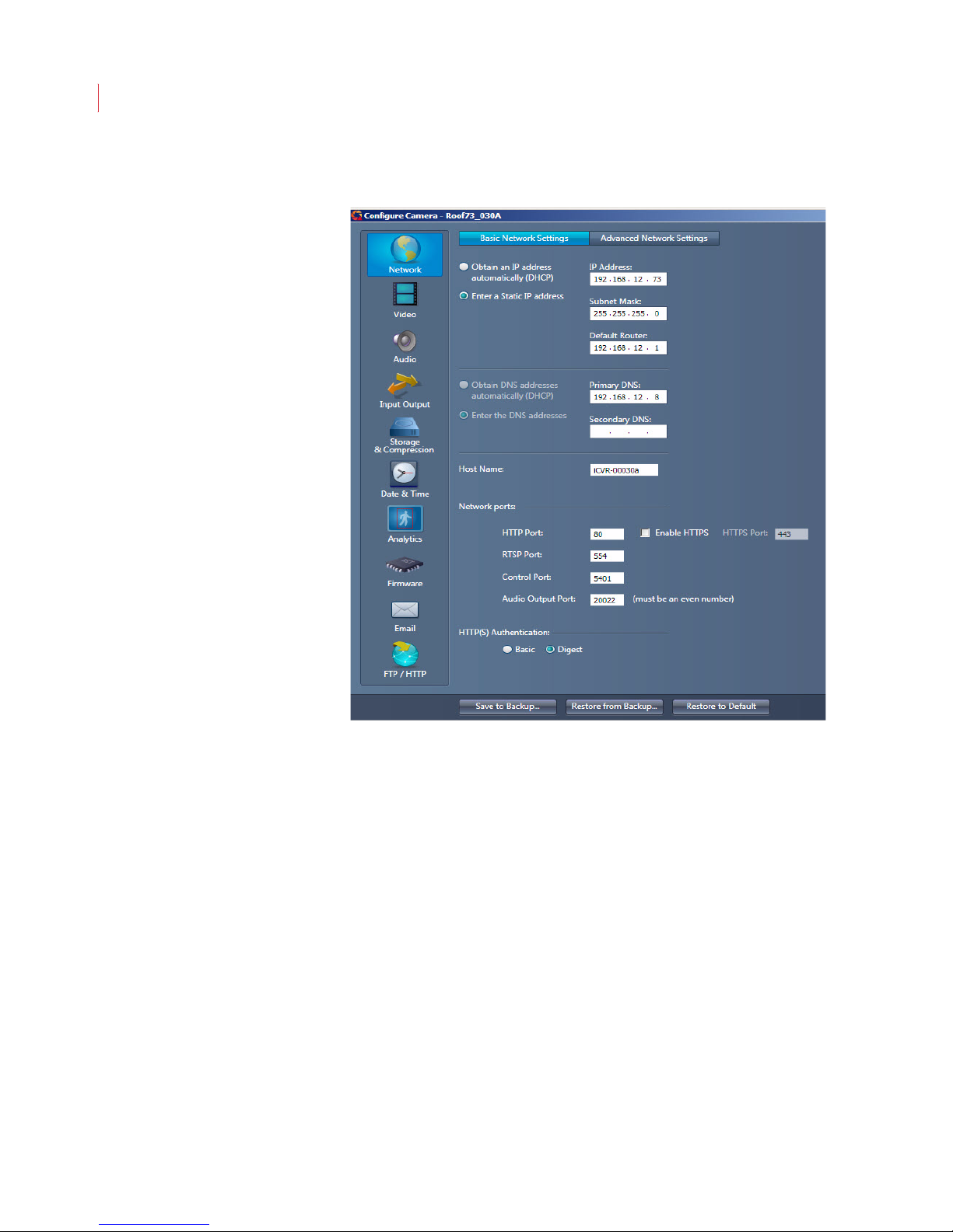
VideoIQ User Guide63
Configuring Basic Network Settings
To configure basic network settings for a camera:
1. When the Configure Camera window opens, click Network.
2. Specify how the camera should acquire its IP address.
If you want the camera to acquire its IP address from a DHCP server,
click Obtain an IP address automatically.
If you want to specify the IP address for the camera manually, click Use
the following IP address and specify the IP address, subnet mask, and
default router for the camera.
3. Specify how the camera should acquire its domain name system (DNS)
server information.
If you want the camera to acquire the addresses for its DNS servers
automatically, click Obtain an IP address automatically.
If you want to specify addresses of your DNS servers manually, click Use
the following DNS server address and specify the IP addresses of your
primary and secondary DNS servers.
4. Specify how the camera should acquire its host name information.
If you want the camera to acquire its host name automatically, click
Obtain a hostname automatically.
Page 74
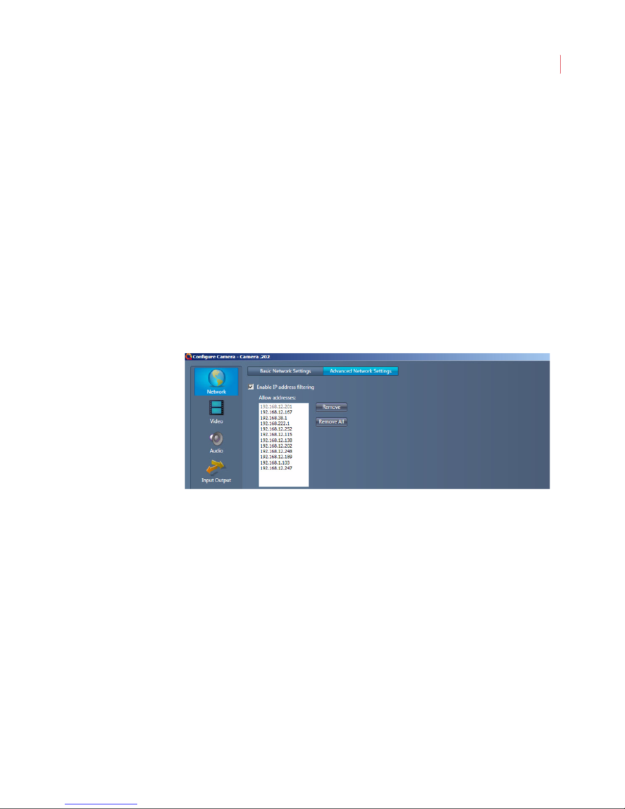
Administering Cameras
If you want to specify the host name for your camera, click Use the
following hostname and specify the host name for the camera.
5. If you don’t want to use the default network ports for communication between
the camera and local server, enter the new port information in the Network
Ports fields.
6. Specify the type of HTTP(S) Authentication to be used:
Basic: When used with HTTP the user names and passwords in the clear
via an unencrypted connection.
Digest: Username and password are hashed prior to being sent across
the unencrypted connection.
7. Click OK.
Configuring Advanced Network Settings
The Advanced Network Settings window lets you control what IP addresses can
communicate with a camera. To filter addresses:
64
1. When the Configure Camera window opens, click Network.
2. Click the Advanced Network Settings tab.
3. Check the Enable IP address filtering box.
4. Click in the Allow addresses field and type the IP address.
5. Click Apply.
The camera will now communicate only with the IP addresses specified.
Page 75
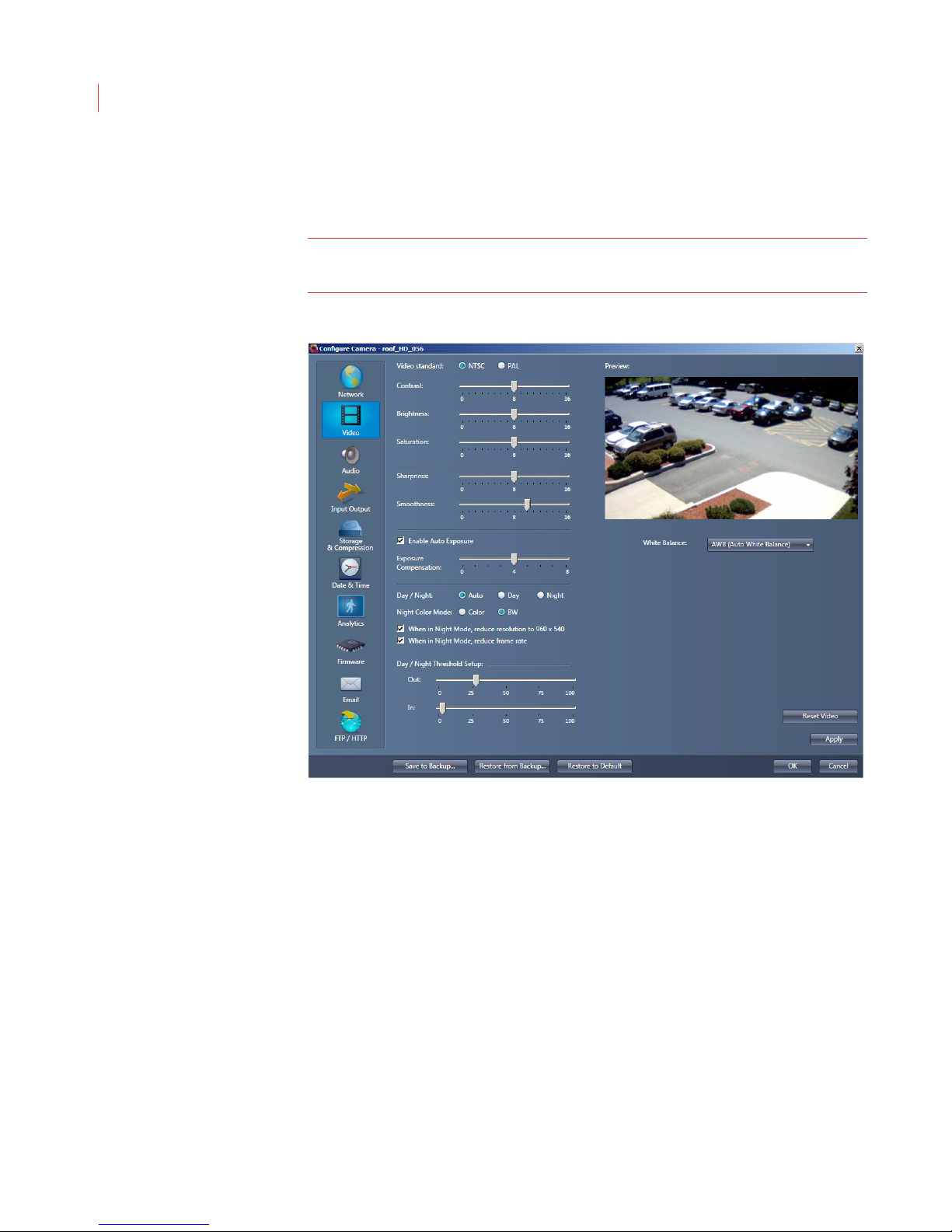
VideoIQ User Guide65
Configuring HD Video Settings
1. When the Configure Camera window opens, click Video.
Note: If you’re using an Encoder you will not see this button. If you’re
configuring a D1 camera see Configuring D1 Basic Video Settings below.
2. Determine the video output by selecting NTSC or PAL.
3. Use the sliders to set image Contrast, Brightness, Saturation, Sharpness
4. Select the Enable Auto Exposure checkbox to enable automatic exposure
5. The Day/Night settings activate an IR cut filter that is in front of the sensor to
6. When the camera is in Night Mode, the Color or BW settings determine if the
and Smoothness.
on the camera. Use the Enhance Compensation selector to enhance bright
or dark areas of the scene.
remove the IR during daytime operation for correct colorimetry.
Auto: The IR cut filter is automatically enabled - In during daytime and
Out at night for maximum sensitivity.
Day: The IR filter is always in the light path.
Night: The IR filter is always out of the light path.
video picture is in color or black and white.
Page 76
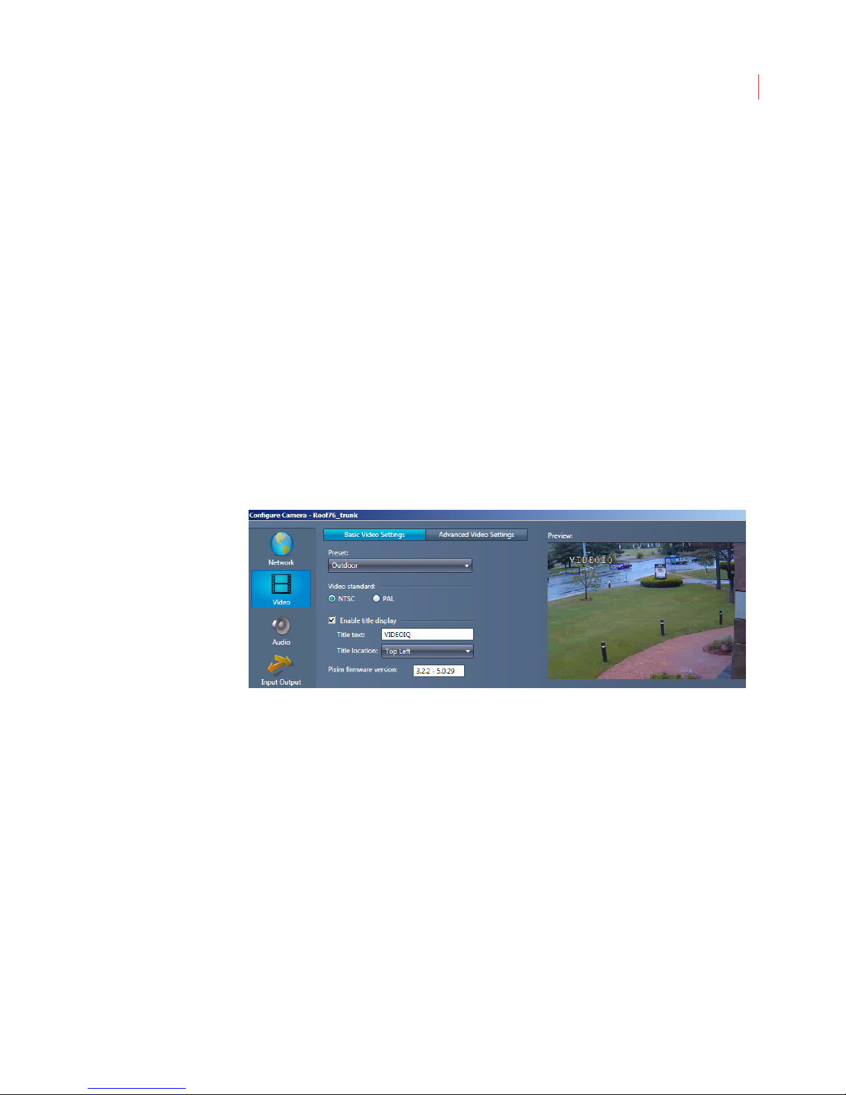
Administering Cameras
7. Select When in Night Mode, reduce resolution to 960 x 540 to reduce
noise.
8. Select When in Night Mode, reduce frame rate to extend the exposure and
capture more light.
9. The Day/Night Threshold Setup settings are for initiating when the change
over from day to night and back again occurs.
Out - Determines when the light level is low enough to move the camera
out of night mode.
In - Determines when the light level is high enough to move the camera
into night mode.
10. Use the White Balance drop-down menu to select a setting for displaying
color depending on lighting conditions.
Use the Reset Video button in the lower right-hand corner of the page to return all
settings to their default value.
Configuring D1 Basic Video Settings
1. When the Configure Camera window opens, click Video. If you’re using an
Encoder you will not see this button.
66
2. Use the Preset drop-down menu to choose the setting that most accurately
describes the lighting where the iCVR is located:
Universal: This is the default setting and is ideal for mixed environments,
Indoor: For indoors with incandescent or high energy lighting.
Fluorescent: For indoors with fluorescent lighting.
such as indoors with nearby windows.
Page 77
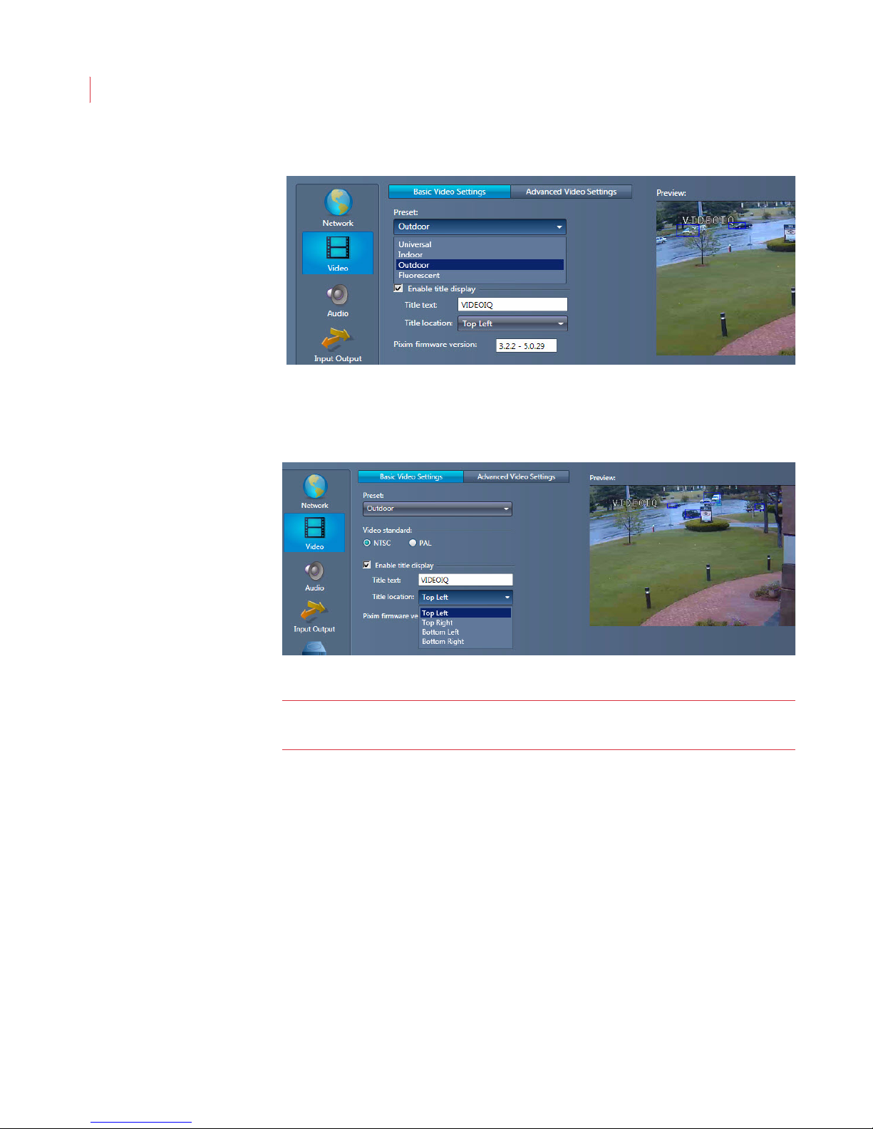
VideoIQ User Guide67
Outdoor: For all outdoor applications.
3. Determine the analog video output by clicking NTSC or PAL .
4. Check the Enable title display if you want to add a title to the video window.
Enter the desired text in the Title text field and use the Title location drop-
down menu to indicate where on the window the title should display.
Note: The location of the title text should not block areas where the camera is
5. Pixim Firmware version - This field is used for VideoIQ technical support
expected to detect objects.
troubleshooting only.
Page 78
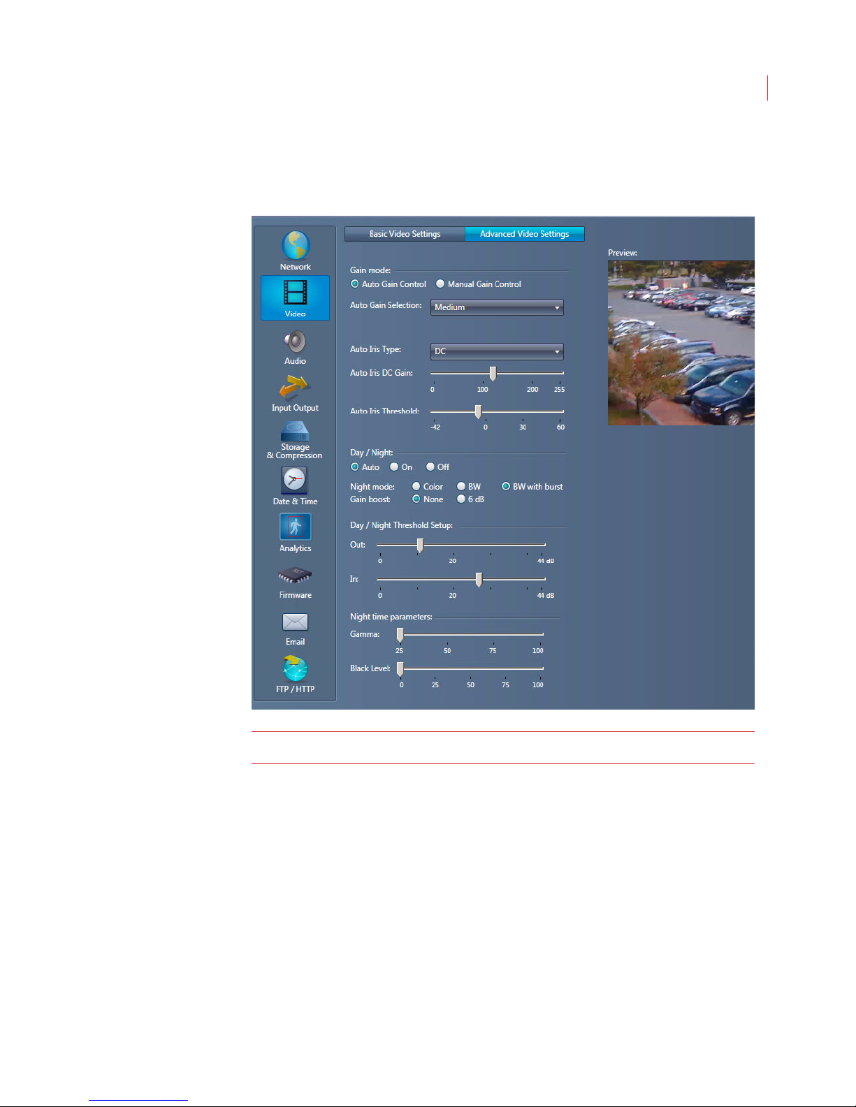
Administering Cameras
Configuring D1 Advanced Video Settings
When the Configure Camera window opens, click Video, then click the Advanced
Video Settings tab.
68
Note: The settings on this page should only be configured by an advanced user.
Gain Mode: This function sets the gain level for the video picture.
Auto Gain Control- Use the drop-down menu to select a pre-determined
Manual Gain Control - Use the slider to specify more or less camera
Auto Iris Type:
Manual - Used for manual iris lenses or to keep the iris fully open.
DC - Allows the sensor to automatically open or close the iris to
Auto Iris DC Gain: Adjusts the iris control gain when using a DC iris.
Auto Iris Threshold: Sets the exposure system gain value (in dB) at which the
electronic iris control ends and auto-iris control begins.
gain level for the video picture.
output for a fixed light environment.
compensate for the change in lighting conditions.
Page 79

VideoIQ User Guide69
Day/Night: These settings activate an IR cut filter that is in front of the sensor to
remove the IR during daytime operation for correct colorimetry.
Auto - The IR cut filter is automatically enabled - in during daytime and
out at night for maximum sensitivity.
On - The IR filter is always out of light path.
Off - The IR filter is always in the light path
Night Mode:
Color - The video picture is always in color.
BW - The video picture goes to black and white during low light for
maximum sensitivity.
BW with burst - The video picture goes to black and white during low
light for maximum sensitivity. A color burst is present for better stability on
a color monitor or recorder.
Gain Boost: These options let you specify additional gain when the camera is
night mode.
None: Will not provide any gain boost. Use this selection for normal video
output.
6db: When in night mode provides added gain. This will give your video
picture extra sensitivity, but can also bring up unwanted noise in your
video picture.
The Day/Night Threshold Setup settings are for initiating when the change over
from day to night and back again occurs.
Out - Determines when the light level is low enough to move the camera
out of night mode.
In - Determines when the light level is high enough to move the camera
into night mode.
Night time Parameters: These settings allow you to adjust the brightness and
grayscale quality of your video picture, and are active only when the camera is in
night mode.
Gamma - Use the slider to adjust the grayscale settings of a video
picture. For the most accurate picture, it’s best to adjust the gamma
setting at night.
Black Level - Under extreme low light it can be beneficial to raise the
black level of a picture. Use the slider to increase or decrease the
brightness of a picture during night operation.
Use the Reset Video button in the lower right-hand corner of the page to return all
settings to their default value.
Note: If you use the Reset Video button it will automatically change the Preset
field on the Basic Video Settings tab to Universal. If your iCVRs are
located outdoors, go back to the Basic Video Settings tab and choose
Outdoor from the Preset drop-down menu.
Page 80
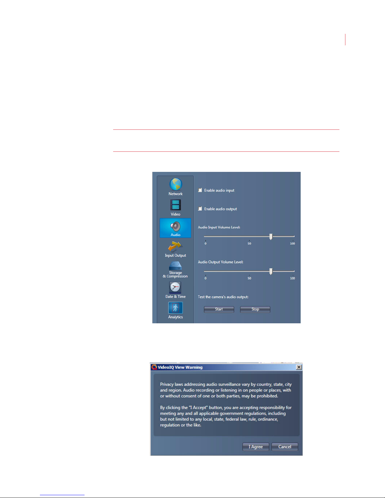
Administering Cameras
Configuring Audio Input and Output
This section describes how to configure the audio input and output features of the
camera.
To record or listen to live audio at the camera an amplified speaker must be
connected to the audio jack. A Y cable is required to use of both audio in and
audio out.
Note: To capture audio on any alarm event you must check the Record audio
box on the Actions tab of a rule
70
Configuring Input
1. Check the Enable audio input box
2. Read and accept the privacy warning.
Page 81
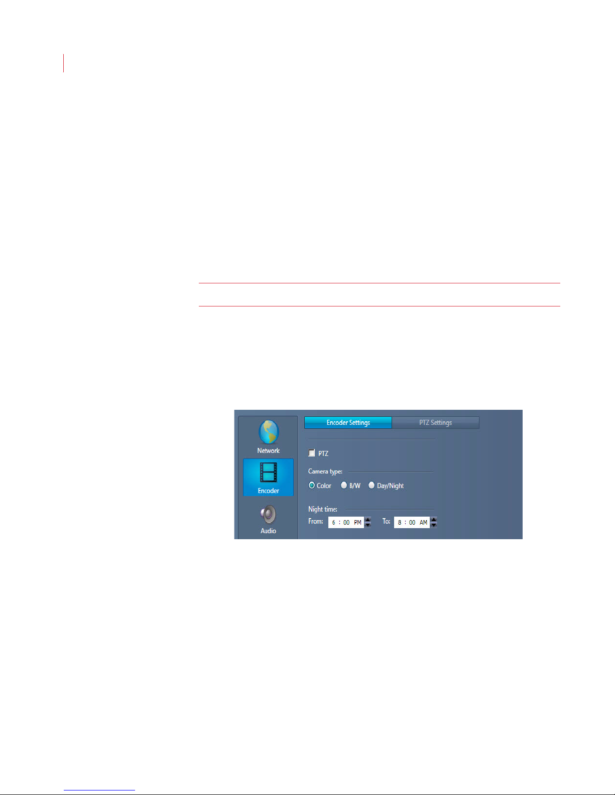
VideoIQ User Guide71
3. Use the slider to adjust the volume level of the audio input.
4. Click Apply.
The speaker icon displays on the camera live video window and alarm review
panel.
Configuring Output
1. Check the Enable audio output box.
2. Click the Start button to start a pre-recorded audio file.
3. Use the slider to adjust the volume level.
4. Click the Stop button.
5. Click Apply.
Note: The iCVR supplies a line-level audio output.
The Talk button displays on the camera live video window, alarm review panel and
the web access Alarm I/O toolbar.
Configuring Encoder Settings
If you’ve attached an analog or PTZ camera to an Encoder you will need to
configure additional settings for the camera.
1. When the Configure Camera window displays, click the Encoder button.
2. If you connected a PTZ camera to the Encoder check the PTZ box. Complete
steps 3 and 4, then proceed to the PTZ Settings tab.
3. Select Color, B/W or Day/Night to correspond to the type of camera that is
connected to the Encoder. If you’ve attached a thermal or infrared camera
select B/W.
4. The Night time setting increases the sensitivity of the video analytics at night.
This setting allows you to set the times for increased sensitivity. Times can be
approximate.
Page 82
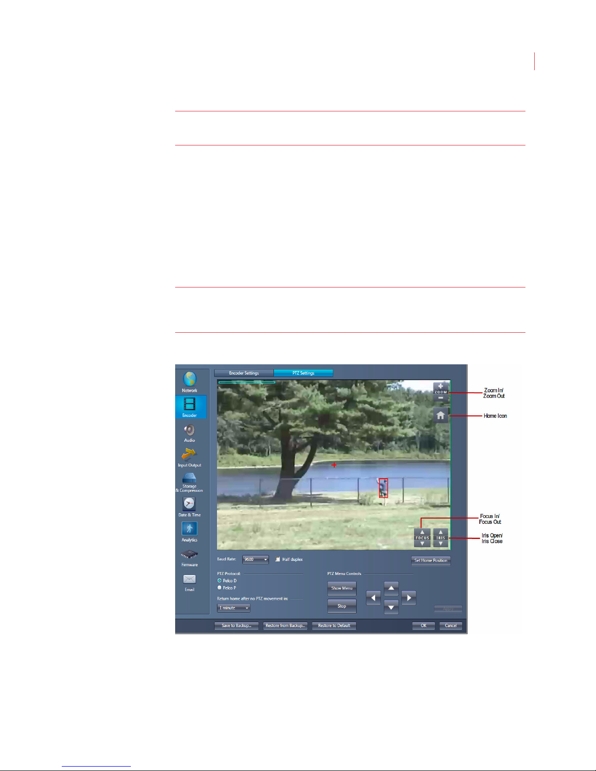
Administering Cameras
Note: The Night time setting applies to all camera types and should be
configured to help the Encoder perform better analytics at night.
Configuring PTZ Settings
Once you have connected a Pelco P or Pelco D PTZ camera to the Encoder you
can use View to:
Configure the on-screen camera menu
Focus the camera
Set the camera Home position
Control the pan, tilt, zoom function of the camera
Note: If you connected a non-Pelco P or Pelco D protocol camera to the
Encoder, some of these feature may not be available to you without
performing additional steps outlined in your camera manual.
72
To configure a PTZ camera that is Pelco P or D compatible:
1. Click the Encoder button on the Configure Camera dialog, then click the PTZ
Settings tab.
Page 83

VideoIQ User Guide73
2. Select the Baud rate that corresponds to the serial configuration of the PTZ
camera. If you’re uncertain what the baud rate of your camera is, consult your
camera manual.
Note: Some PTZ cameras use an autobaud algorithm and do not allow you to
set a baud rate. If you have this type of camera, select your baud rate,
and press and hold the Stop button until the PTZ autobaud function is
completed.
3. Indicate if the PTZ camera you’re configuring is Half duplex.
4. Set the PTZ Protocol for either Pelco D or Pelco P.
5. Click OK.
Home
Using the Encoder, video analytics are supported on one preset PTZ location,
which is referred to as the Home position. The Home position of the camera is
indicated by a red plus sign on the live video window.
Note: Analytics operates only when the camera is in the Home position. Once
the camera has left this position it will continuously record, but analytics
will not be active.
1. To set or change the Home position use the directional arrows or click your
cursor in the live video window to move the position of the camera, then click
the Set Home Position button.
On some cameras, clicking the Set Home Position button may bring up the
on-screen camera menu. If you see this behavior consult your camera
manual to determine what additional steps are needed to set the Home
position.
2. Use the Return home after no PTZ movement drop-down menu to select
how quickly you want the camera to return to its Home position after manual
PTZ control has stopped. The camera will automatically return to the Home
position after this time period has elapsed, and the analytics will re-engage
automatically. If you don’t want it to return to the Home position automatically,
select Never.
Page 84
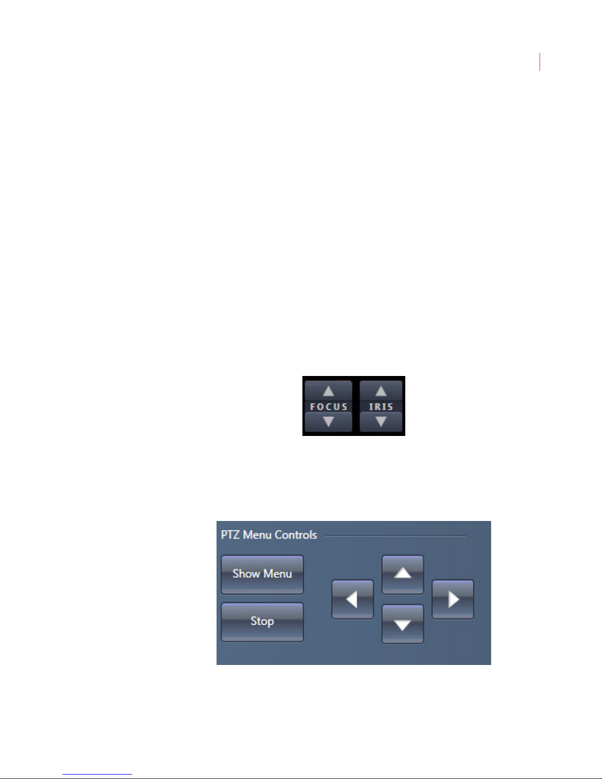
Administering Cameras
To immediately return the camera to the Home position, click the Home icon in the
live video window.
Controlling Camera Movement
You can use View to control the movement or change the direction of the camera
two different ways:
By clicking anywhere on the live video window to move the camera in the
corresponding direction. The speed of the camera increases the further
your cursor is from the center of the video window, which is indicated by
the red plus sign.
By using the Plus and Minus icons in the live video window you can
control the zoom function of the camera. Move the cursor over the
window to enable the Home, Zoom, Focus In/Focus Out, and Iris
Open/Iris Closed buttons.
Focusing the Camera
74
The Focus In/Focus Out buttons located on the live video window allow you to
adjust the focus of the camera.
Configuring the Camera Menu
The PTZ Menu controls allow you to navigate your on-screen camera menu from
within View. Click the Show Menu button to display the camera menu, and use
the Up/Down/Right/Left directional arrows to navigate through the menu.
Page 85
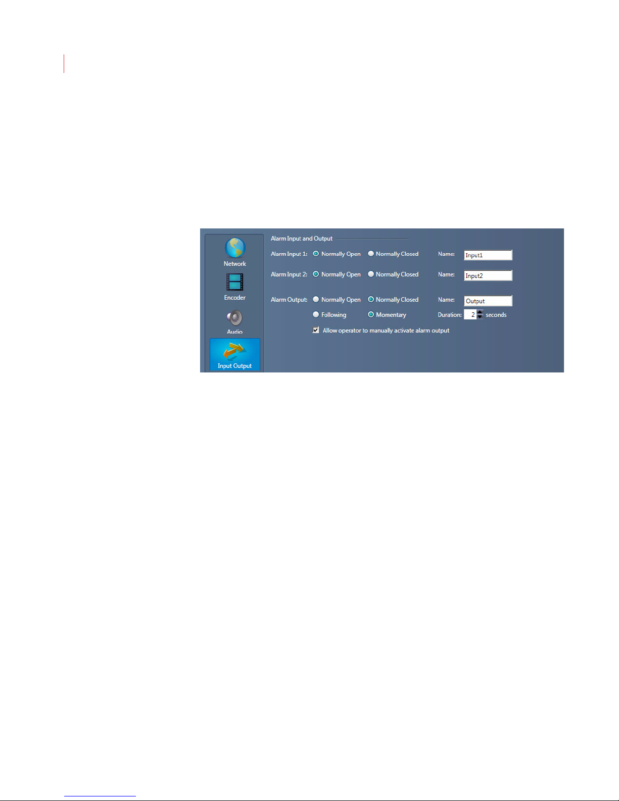
VideoIQ User Guide75
On certain cameras you may also need to use the Focus In/Focus Out and Iris
Open/Iris Close buttons to operate the on-screen menu. Refer to your PTZ
camera manual to see what additional steps are needed.
Configuring Input/Output Settings
The Input/Output Settings window lets you configure settings for alarm inputs
and outputs attached to your camera. Changing the settings on this page
1. When the Configure Camera window opens, click Input/Output.
2. Use the Alarm Input option buttons to specify if the input device signal is
Normally Open (high) or Normally Closed (low).
a. Change the name of the input field label by entering up to eight
characters in the Name field; then click Apply. The changed label name
displays in the Alarm I/O toolbar on the camera web page.
3. Use the Alarm Output options button to specify if you want the alarm output of
the iCVR to be Normally Open or Normally Closed.
a. Use the Following button to specify if you want the output device to be
triggered for the duration of the rule violation.
b. Use Momentary to specify if the output device should be triggered for a
fixed amount of time. Enter the desired number of seconds in the
Duration field.
4. To enable the Output button on a live video or alarm review window, check
Allow operator to manually activate alarm output, This also enables the
Output button on the Alarm I/O toolbar when accessing a camera via a web
browser.
a. Change the name of this button by entering up to eight characters in the
Name field; then click Apply.
5. Click OK.
Page 86
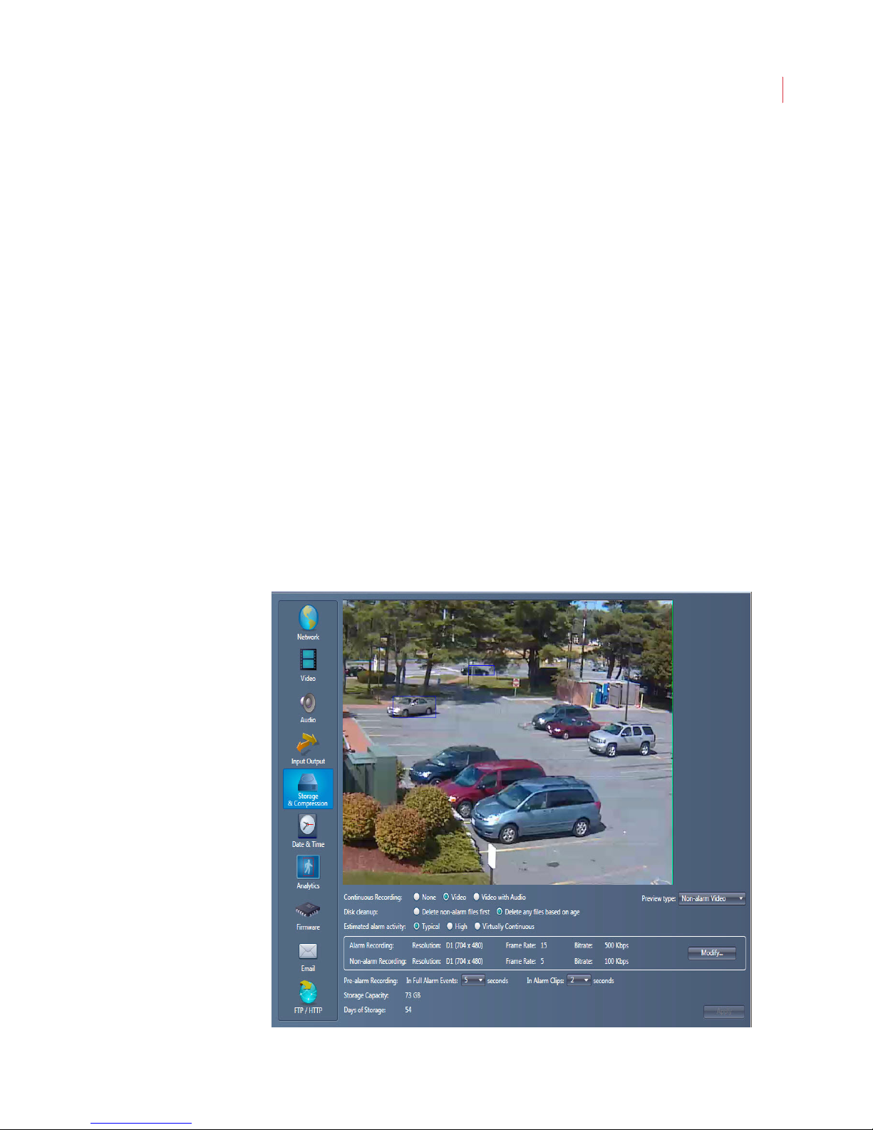
Administering Cameras
76
Configuring Storage and Compression Settings
The Storage and Compression Settings window lets you configure the picture
quality, video storage and compression level of your video.
1. When the Configure Camera window opens, click Storage & Compression.
Page 87

VideoIQ User Guide77
2. The Preview type drop-down menu allow you to see either your alarm or non-
alarm videos based on the current bitrate and storage compression settings.
To preview high-quality video, select the Alarm Video option.
To preview the low-quality, continuous record video, select the Non-alarm
Video option.
3. The iCVR allows recording and monitoring of 2 video streams: a high-quality
video stream for alarms, and a low-quality video stream that can be used to
record continuously. If you want to continuously record low-quality video
select Video or Video with Audio. When you choose Video with Audio you
will be asked to read and accept a privacy warning.
If you do not want to record continuously select None. This will ecord event
video only.
Note: Recording video with audio will double the size of the alarm clips.
4. The Disk Clean-up option allows you to decide which files are deleted when
the storage within the iCVR is filled. Selecting Delete non-alarm files first
will keep alarm files and delete continuous recording files first.
Note: After months of usage, this could result in only 1 days worth of continuous
recordings and the rest of the disk will retain alarm files.
If you select Delete any files based on age, this will delete the oldest files
first.
5. Use the Estimated average alarm activity option buttons to specify the
expected number of alarms. This is used to estimate the number of days that
video will be stored on the iCVR hard disk.
Typical - Alarm events occur up to 30% on average.
High - Alarm events occur 30%-50% on average.
Virtually continuous - Alarm events are occurring more than 50% of the
time on average.
6. Click the Modify button to change the Resolution, Frame Rate and Bit Rate
for alarm and non-alarm recording. Available rates will change based on the
resolution chosen.
7. Use the Pre-alarm Recording drop-down menus to specify the number of
seconds prior to an alarm being triggered that are recorded for full alarm
events or an alarm clip.
8. The Storage Capacity field reflects the size of the camera’s disk space.
9. Days of Storage reflects the number of days of storage based on the settings
you’ve selected.
10. Click Apply. Review the quality of the video in the Preview window and make
any configuration adjustments necessary.
Page 88
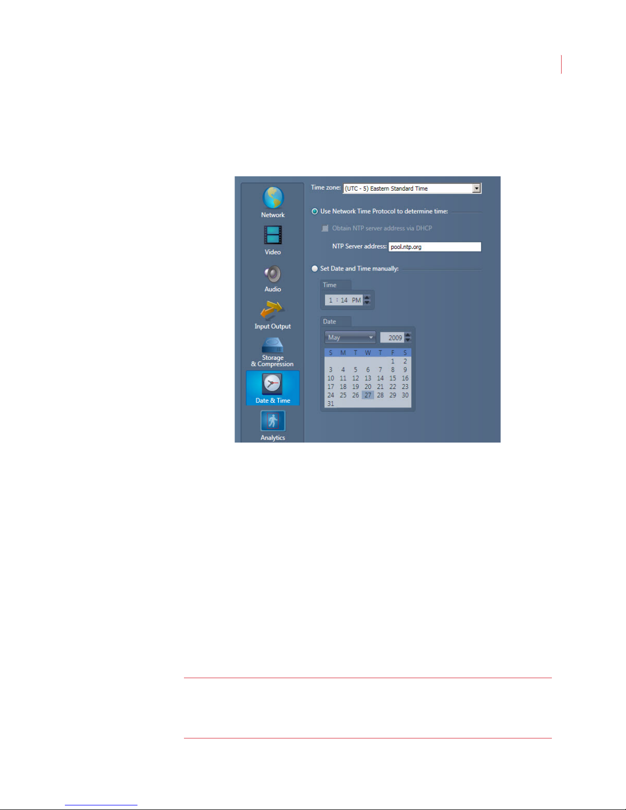
Administering Cameras
Configuring Date and Time Settings
The Date and Time Settings window lets you configure the time zone for each
camera or camera group.
78
1. When the Configure Camera window opens, click Date & Time.
2. Use the Time zone list to specify the time zone in which the camera is
operating.
3. When a Network Time Protocol (NTP) server is available, VideoIQ
recommends using it to synchronize the camera, To do this, click the Use
Network Time protocol to determine time
If you want to use DHCP to select a NTP server, check the Obtain NTP
button.
Server via DHCP check box.
If you want to specify a NTP server for the camera, uncheck the Obtain
NTP Server via DHCP box and enter the IP address or DNS name of the
NTP server in the NTP Server address field.
4. When an NTP server is not available, click the Set Date and Time manually
button and use the Date and Time controls to specify the current date and
time.
5. Click OK.
Note: Note: The iCVR does not contain a battery backup for a real-time clock.
VideoIQ strongly recommends that you configure the iCVR to get its time
through an NTP server, which allows the iCVR to always have accurate
time.
Page 89
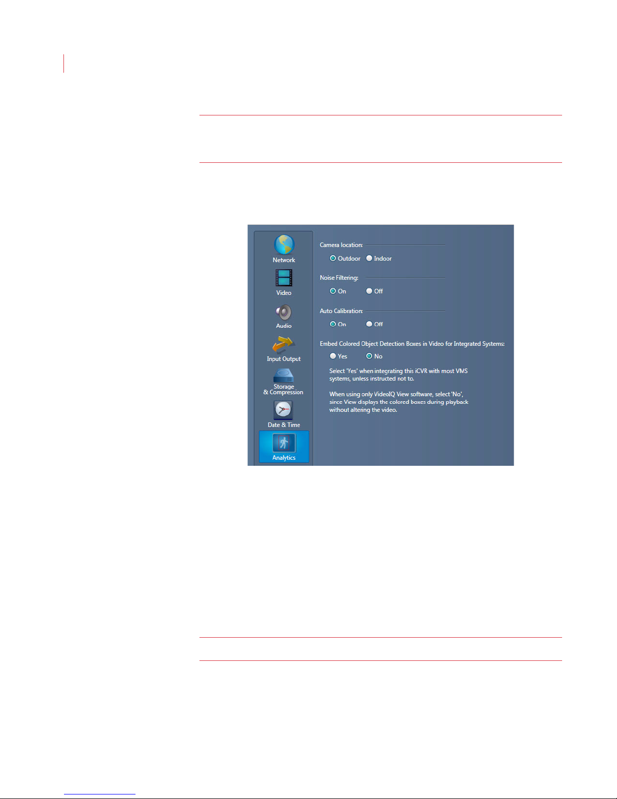
VideoIQ User Guide79
Note: If an NTP server is not available or if you have unreliable network
connectivity, you can also use a UniKey USB dongle to maintain accurate
time. To purchase a UniKey dongle, please contact VideoIQ.
Configuring Analytics Settings
To help improve video analytics, configure the following settings:.
1. Select either Outdoor or Indoor. Selecting Indoor will focus the analytics on
detecting people, including times when they are partially obscured. Indoor
mode does not support vehicle detection.
When you select Outdoor, all objects are detected.
2. Choose to turn Noise Filtering On or Off.
3. Auto Calibration
On:The camera automatically calibrates.
Off: If no humans are expected to be in the camera’s field of view, or
humans and vehicles move on multiple surfaces separated in height, turn
off auto-calibration.
Note: When auto-calibration is turned off you may see more false positives.
4. If you use View to watch and review video clips, select No for Embed
Colored Object Detection Boxes in Video for Integrated Systems. If your
iCVR is integrated with a VMS system, select Yes.
5. Click Apply.
Page 90
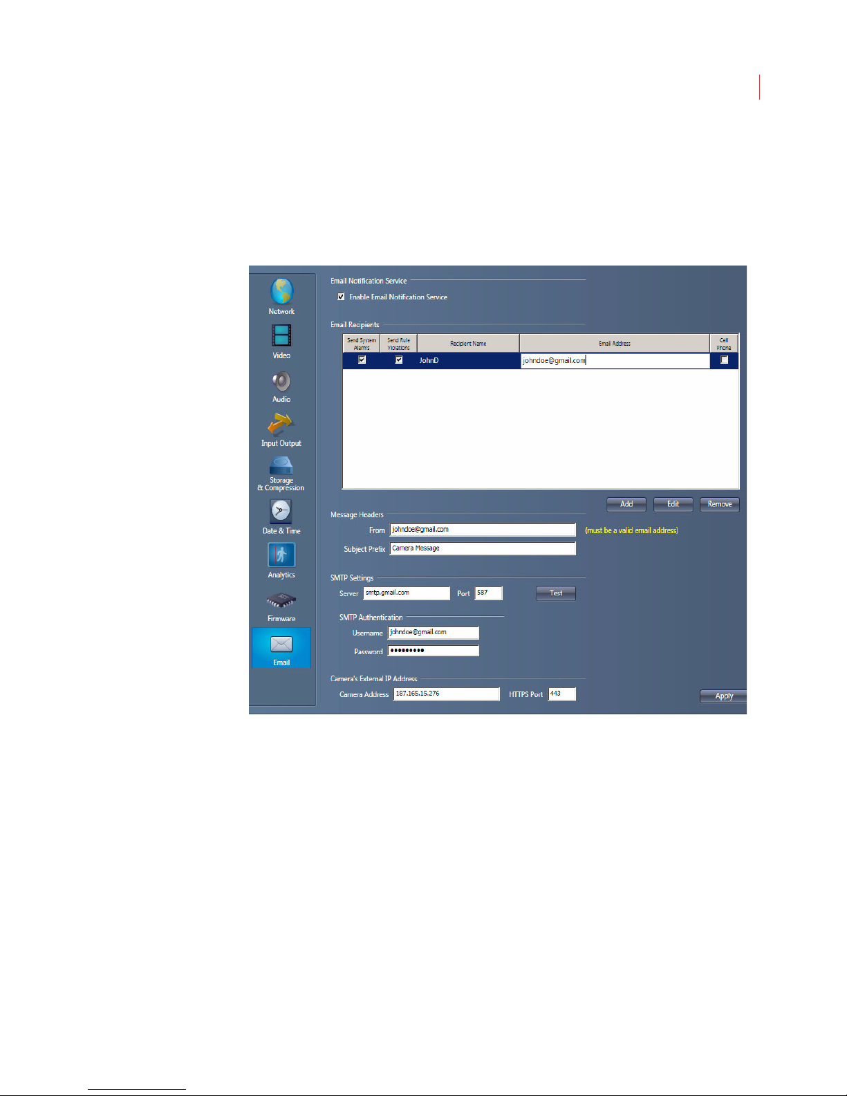
Administering Cameras
Configuring Email Settings
Email Settings work together with Send email notification on the Actions tab of
a rule to allow you to receive system alerts or rule violations when not logged into
View. The notification lists the camera name, rule violated or system alert, and
links to the video alarm clip as well as live video.
80
1. When the Configure Camera window opens click Email.
2. Ensure that the Enable Email Notification Service box is checked.
3. Click the Add button to enter the name and email address of the person
receiving alerts. You can enter up to seven email addresses per camera.
a. Send System Alerts: Sends an email when systems alerts such as
b. Send Rule Violations: Sends an email when a rule violation occurs.
c. Cell Phone: Sends a text-only message to the recipient’s cell phone.
4. Fill in the Message Headers:
a. From: This is the email address of a user on the SMTP server, and will
b. Subject Prefix: Text entered in this field will appear at the beginning of
scene changes or a camera reboot occur.
show as the sender of the notifications.
the email Subject line, allowing you to filter incoming notifications from
your other emails.
Page 91
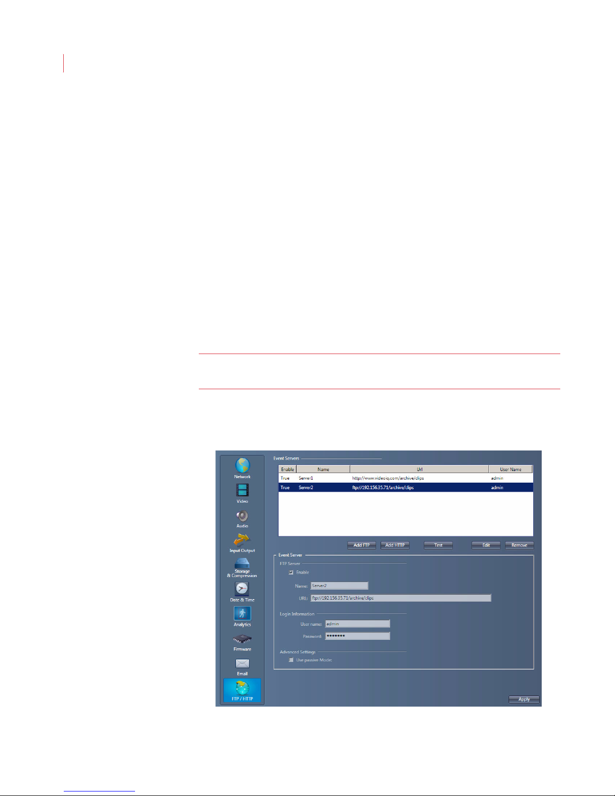
VideoIQ User Guide81
5. Enter the name or IP address of the SMTP server in the SMTP Settings:
Server field. Enter port information when using a non-standard port.
6. Enter login credentials for the SMTP server in the SMTP Authentication
fields.
7. Enter the Camera’s External IP Address and HTTPS Port number to view
video when the camera is behind a firewall or router.
8. Click Apply.
The following is an example of configuring these settings for GMail
From: [email protected]
Server: smtp.gmail.com
Port: 587
Username: [email protected]
Password: Password
Once you’ve finished configuring the email settings, use the Test button to verify
the settings work. If the settings are correct you will receive a test email message.
Note: To complete the setup you must enable Send email notification on the
Actions tab for the rule you want to receive notifications from.
Configuring FTP/HTTP
To receive alarm clips and alarm information without using View, configure an FTP
or HTTP server. When an FTP server is configured you receive alarm clips only.
Page 92
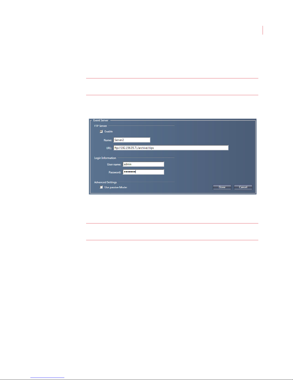
Administering Cameras
When an HTTP server is configured you receive the alarm data, with option of
also receiving the alarm clip.
You must be logged into View as a supervisor to configure these settings.
Note: Ensure that the appropriate ports are open in the firewall to allow the
server to receive alarm clips and/or data from the camera.
Configuring FTP
82
1. Click Add FTP.
2. Check the Enable box.
Note: If you have multiple ftp servers set up in View, each with the Enable box
checked, alarms clips will be sent to each server.
3. To organize servers in the Event Servers field, enter a Name.
4. Enter the address of the server in the URL field. You can enter a full directory
path to store all alarm clips in a specific directory.
5. Enter the User name and Password used to login into the server.
6. Click the Test button. If the fields are configured correctly a file will be
transfered to your ftp server.
7. Check Use passive Mode to send the alarm clip in passive mode; uncheck
the box to send in active mode.
8. Click Done, then click Apply.
Page 93
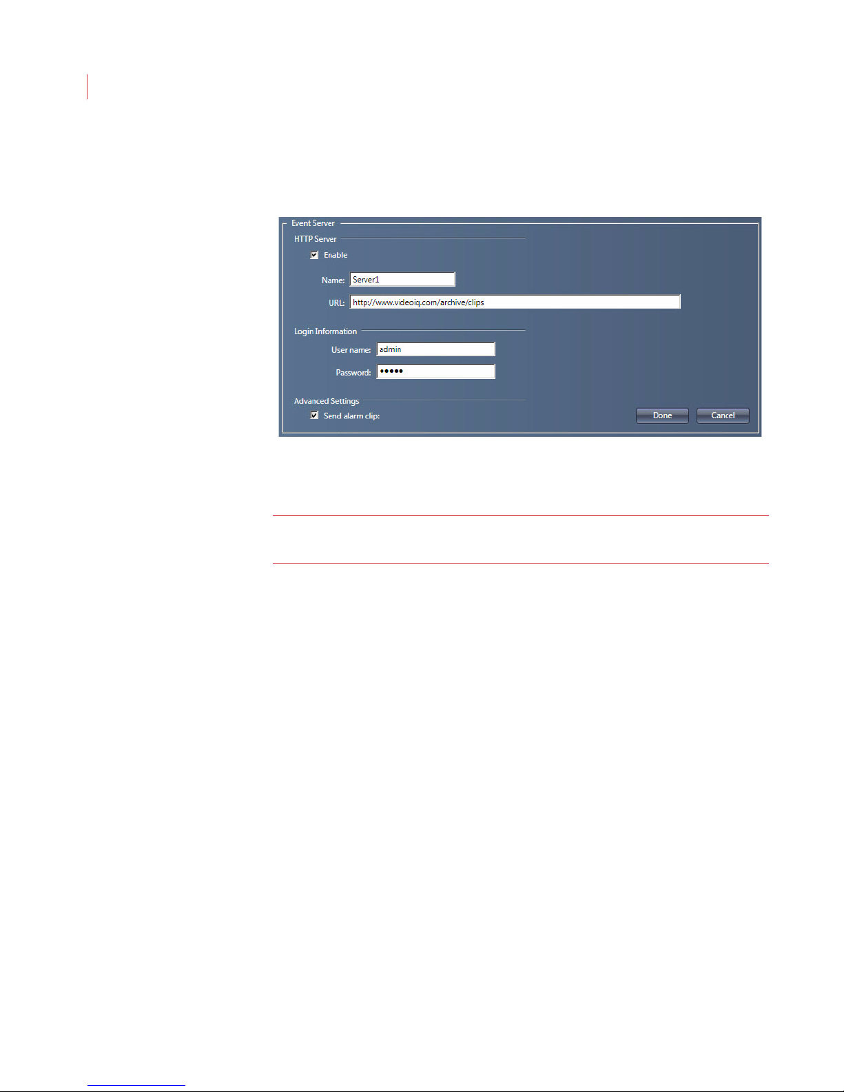
VideoIQ User Guide83
Configuring HTTP
1. Click Add HTTP.
2. Check the Enable box to activate this entry in View.
Note: If you have multiple HTTP servers set up in View, each with the Enable
box is checked, alarms clips will be sent to each server.
3. To organize servers in the Event Servers field, enter a Name.
4. Enter the address of the server in the URL field. You can enter a directory
path to direct all post requests to this full URL.
5. Enter the User name and Password used to login into the server.
6. Click the Test button. If the fields are configured correctly a file will be posted
to your server.
7. To receive alarm clips in addition to alarm data, check Send alarm clips.
8. Click Done, then click Apply.
To view an alarm clip double-click on the file. The clip will display in Windows
Media Player.
Page 94

10
Viewing Live Video
This chapter describes:
Viewing Live Video
Viewing Live Video Across Two Monitors
Using Zoom
Using the Live Alarm Pop-Up Window
Using IQTrack
Listening to Audio
Alarm Events
Viewing Live Video
You can view live video from an iCVR by clicking the Live Video button on the
View toolbar, then double-clicking on a camera in the camera tree. A camera can
also be dragged from the tree and dropped into the display area.
To change the size of a live video click the Small/Medium/Large icons, or the Full
Screen button, in the upper right corner of the window.
Cameras can be rearranged by dragging each window into a different position in
the display area. You may view video in 1 large, 4 medium sized, or up to 16 small
windows at the same time.
Note: When displaying live video in medium or small windows, the lower quality
While viewing video, bounding boxes indicating different object types will display
on the screen:
Red boxes indicate humans.
Blue boxes indicate vehicles or boats.
Yellow boxes indicate suspicious objects.
Use the Preferences dialog box to configure which boxes you want displayed. See
Chapter 6: Configuring View Preferences for more information.
stream is used, conserving overall bandwidth.
Page 95
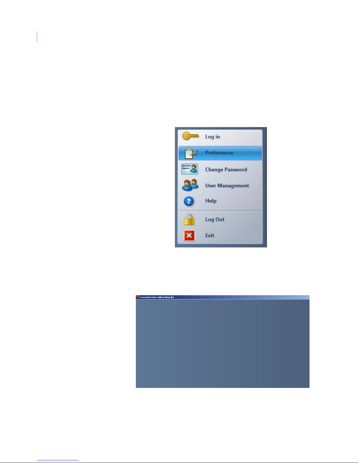
VideoIQ User Guide85
Viewing Live Video Across Two Monitors
You can view live video across two monitors using the Extended Live Video
window.
To display an extended View window:
1. Ensure that your computer is configured for multi-monitor support in.
2. Click the VideoIQ button in the toolbar and select Preferences.
3. When the Preferences dialog box displays, ensure that the Enable Extended
Live Video View box is checked, then click OK.
4. Select the Extended Live View button from the View toolbar. The Extended
Live Video View window displays.
If you’re opening the Extended Live Video window for the first time, it will display
in front of the main View window. You can move it by clicking and holding the title
bar of the window while dragging it to a second monitor.
Page 96
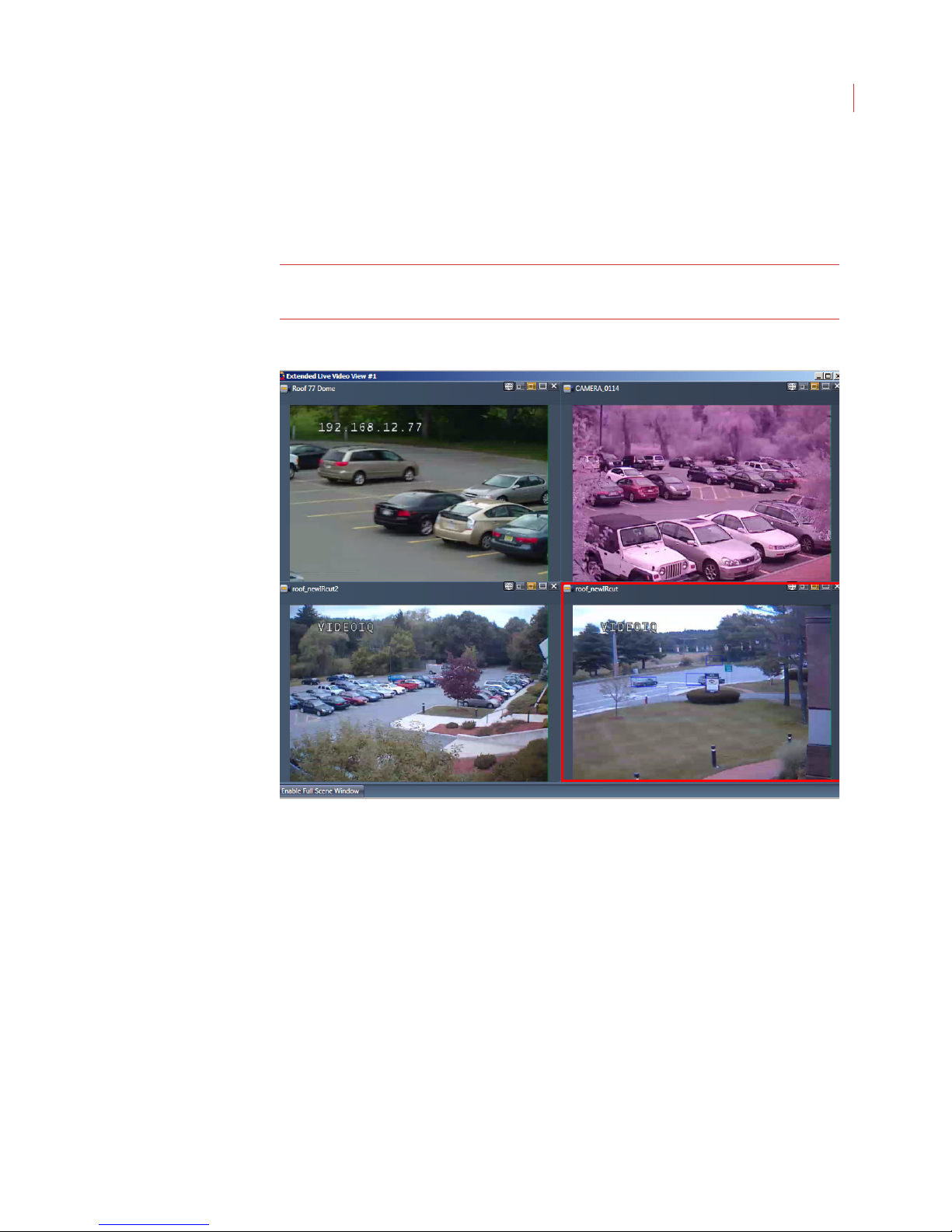
Viewing Live Video
You can add cameras or groups to the Extended Live Video window by doubleclicking on them in the camera tree or dragging them from the main View window.
Camera windows can be moved between the main View window and the
Extended Live Video window.
Note: A camera cannot display on both the main View window and on the
Extended Live Video window.
86
The cameras on the Extended Live Video show in the camera tree and alarm
event panel of the main View window.
If you minimize the Extended Live Video window you can restore it by clicking the
Extended Live View button in the View toolbar.
When you use the zoom controls or IQTrack feature with a camera window
displaying on the Extended Live Video window, a full scene window will also
display.
The extended View window closes when you exit View.
Page 97
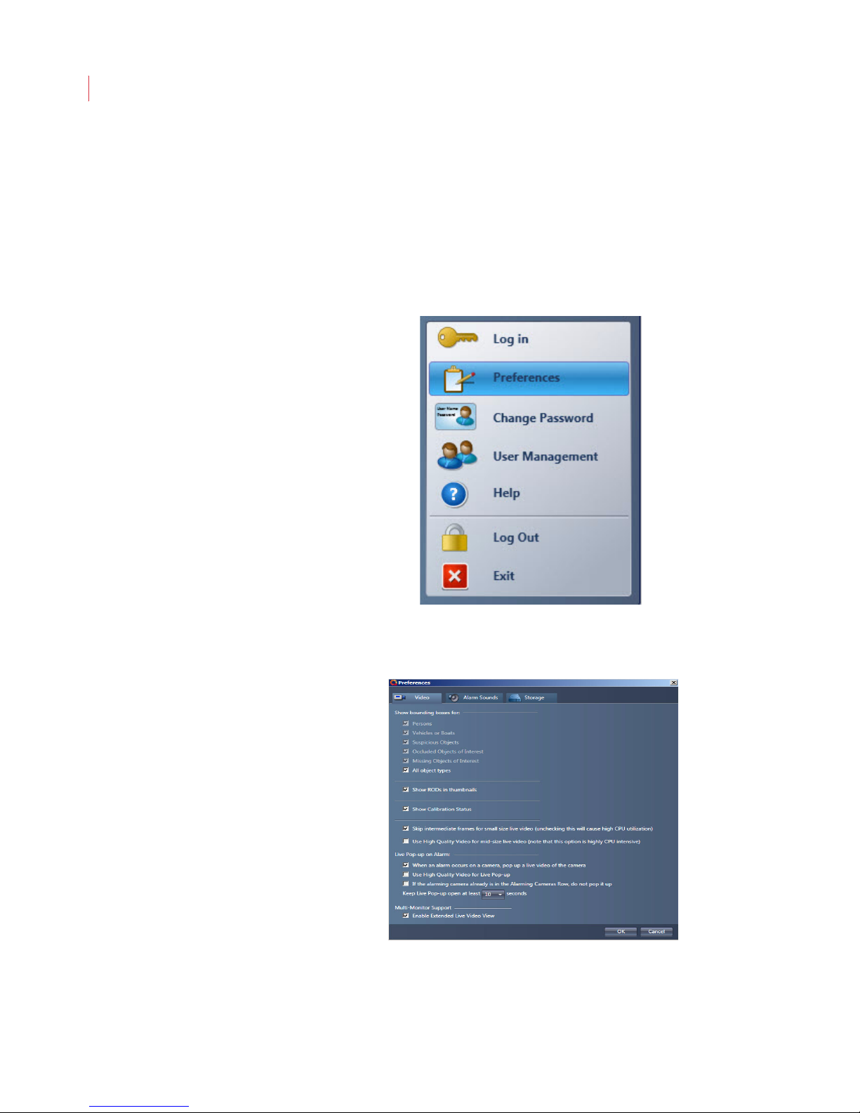
VideoIQ User Guide87
Using the Live Alarm Pop-Up Window
The live alarm pop-up window displays live video alarms from cameras that you
are logged into, regardless of whether that camera is displaying in the Live Video
area. When monitoring multiple cameras it provides an easy way to see the most
recent alarms.
To enable the live alarm pop-up window:
1. Click the VideoIQ button in the toolbar and select Preferences.
2. When the Preferences dialog box displays, ensure that the When an alarm
occurs on a camera, pop up a live video of the camera box is checked.
3. Determine if you want to use high-quality video for the pop-up alarms.
4. Determine if you want alarm windows already showing in the Alarming
Cameras row to show as a pop-up window.
Page 98
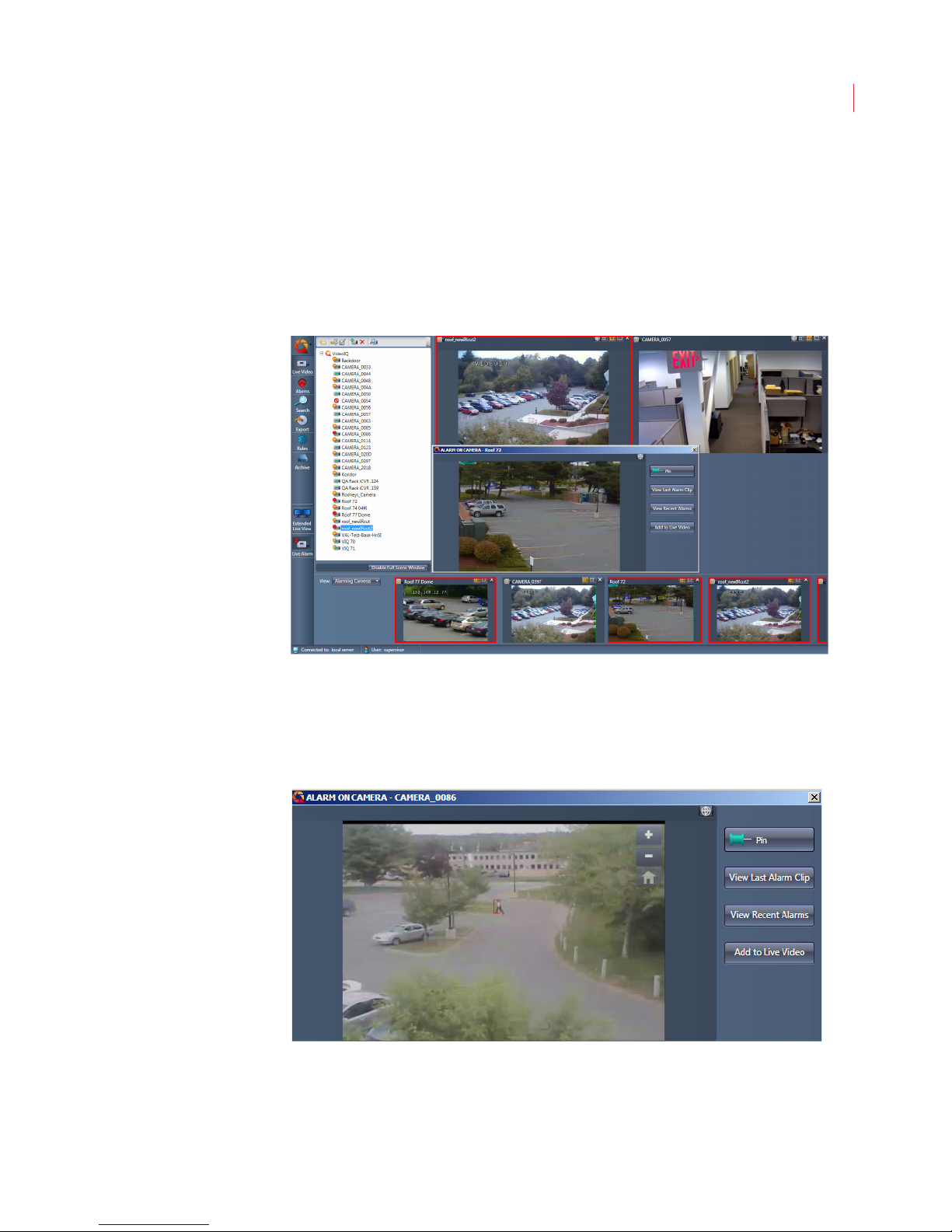
Viewing Live Video
5. Set the number of seconds to keep a live alarm window open.
6. Click OK.
7. Click the Live Alarm button on the View toolbar.
Once the Live Alarm button has been selected, the pop-up alarm window will
begin displaying on top of the main View window. You can move the window by
clicking the title bar and dragging the window to a new location
88
The zoom buttons and IQTrack functionality are available on the live alarm pop-up
window. Depending on the camera’s settings you may also see the Listen, Talk or
Output buttons.
Pin: When an alarm window is pinned it will remain open until it’s
unpinned. If an alarm occurs on a different camera, the alarm window
displays in red in the alarm events panel. When an alarm window is not
Page 99
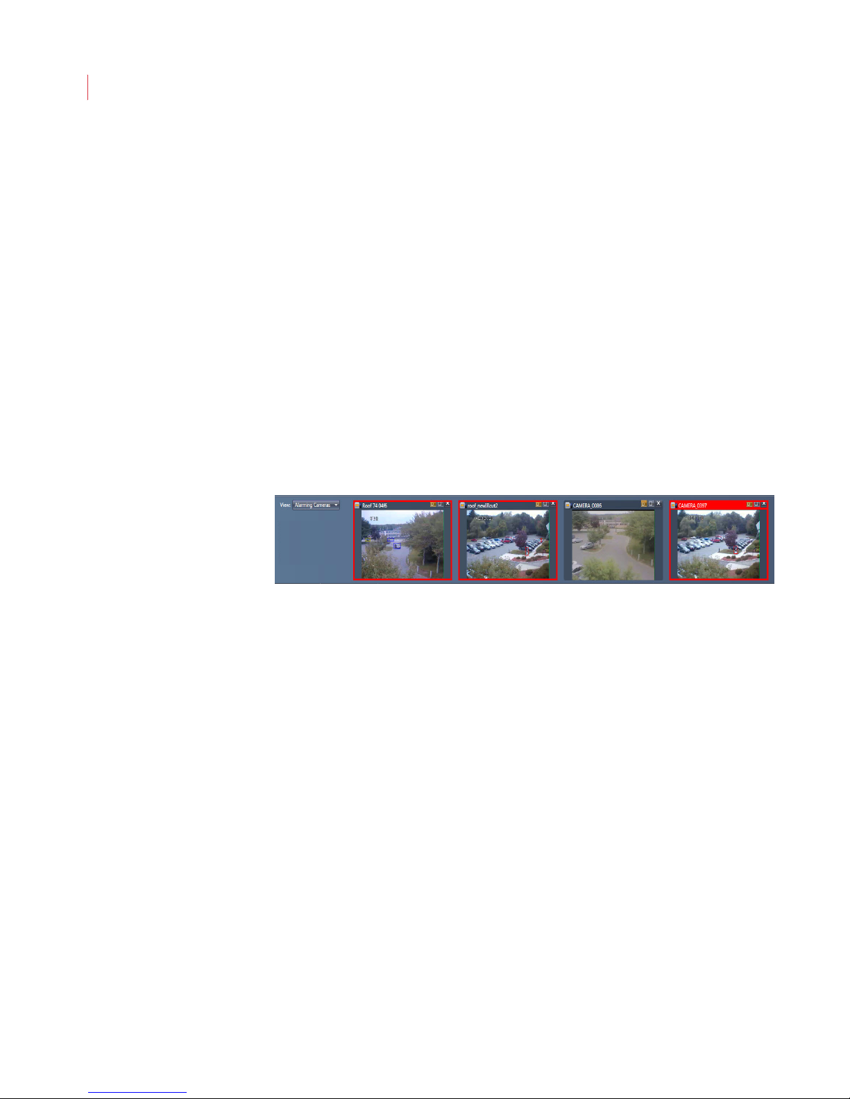
VideoIQ User Guide89
pinned it automatically closes and reopens if a new alarm occurs on a
different camera.
View Last Alarm Clip:This button displays an alarm play-back window
with the last alarm clip for this camera. Once this button has been
selected it will pin the window.
View Recent Alarms: This button displays a window that show the
alarms that have occurred on this camera in the last hour. Once this
button has been selected it will pin the window.
Add to Live Video: This button adds the camera to the Live Video area if
the camera window is not currently displayed.
Viewing alarming cameras in the alarm event panel:
The alarm event panel in View allows you to view alarms in timeline, list or
alarming cameras format. When you have the Alarming Cameras view selected
the panel displays windows from up to four cameras.
As each new alarm displays in the pop-up window the alarm window from the
previous camera is moved to the alarm event panel. The oldest window is
removed from the panel when the four-camera limit is reached.
When a camera displaying in the panel has an active alarm, the window is
outlined in red. The window with the latest alarm displays with a red title bar.
To return a window in the panel to the pop-up alarm window, click the medium
button in the window. If the pop-up window is already open, the camera displaying
will move down to the alarm event row. When the “If alarming camera already is
in the Alarming Cameras Row, do not pop it up” preference is set, the camera
will remain in the alarm event panel and will not display in the pop-up window.
To disable the pop-up alarm window click the Live Alarm button.
Page 100
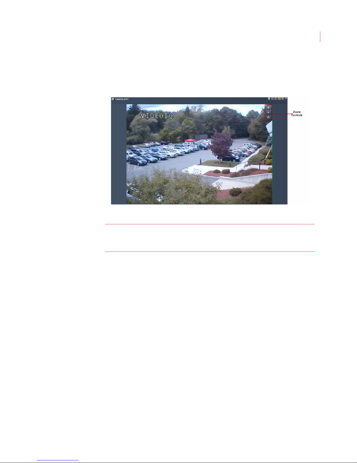
Viewing Live Video
Using Zoom
Use the zoom controls to quickly zoom in or out on an object or area in a camera
window.
90
Note: The zoom functionality described in this section takes place on the View
software. If you have View looking at an encoder connected to a PTZ
camera, the zoom functionality is done on the camera.
To view the zoom controls move your cursor over the camera window.
There are three different ways to zoom in on an object or area:
Pressing and holding the Zoom In control.
Double-clicking your mouse in the camera window. This zooms the
camera image by 2X and centers the image at the point of the doubleclick.
Using the wheel control on your mouse.
Zoom out by pressing and holding the Zoom Out control.
Return the camera to its original magnification by clicking the Home button.
When the camera is in zoom mode you can change the focus of the video
displaying in the camera window by clicking and dragging the image in the
window. To do this:
1. Move your cursor over the camera window. The cursor changes to an open
hand.
2. Click the left mouse control and drag the image to the desired location. The
cursor changes to a closed hand until you release the mouse control.
When a camera window is in zoom mode you can point the zoomed area in the
window by executing a single mouse click within the window. This will center the
point of view at the location where the mouse was clicked. This same action can
be performed in the Full Scene window, described in the next section.
 Loading...