

Page 1

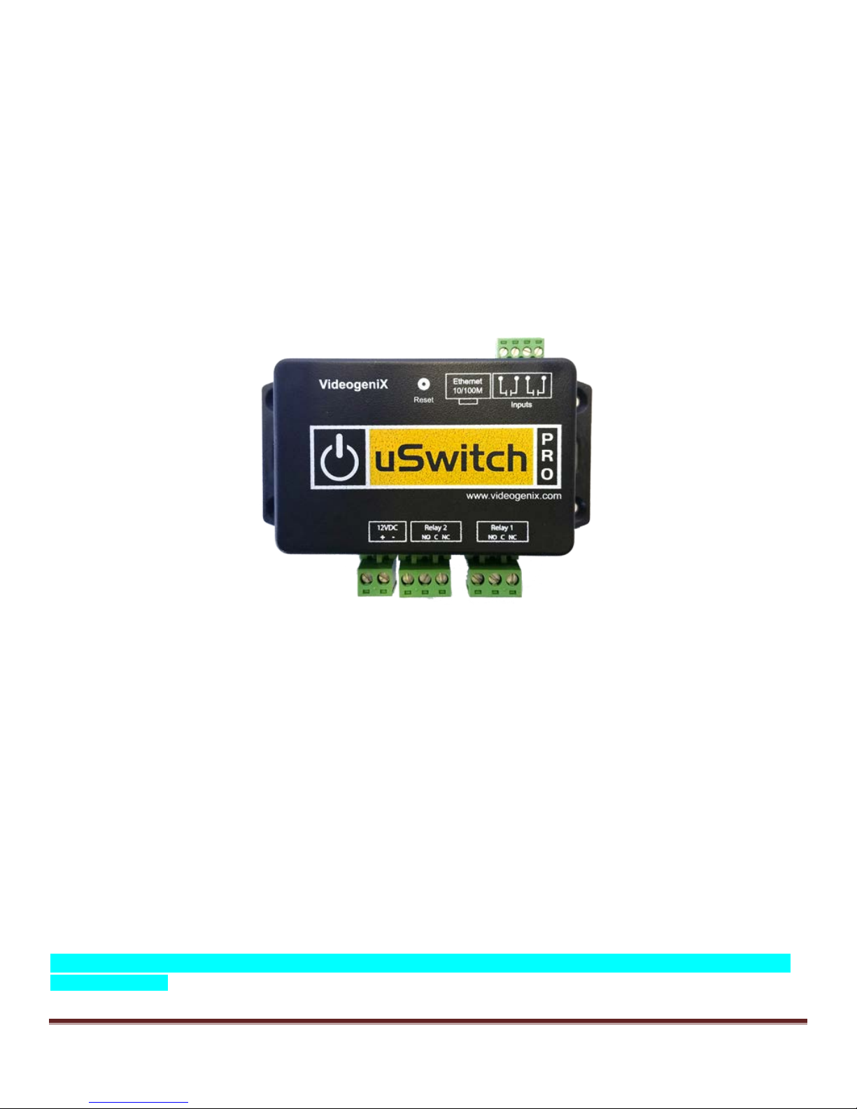
uSwit ch™ and uSwi tchPr o™ Installa tio n
and Operating Manual
a nd t he A-Plug Adapter
uS witch and uSwitchPro Inst allation and O perating Manual Page 1
Page 2

Table of Content s
Introduction ................................................................................................................................................................3
uS witch and uSwitchPro Features................................................................................................................................4
Installation Guideli nes (Read before Instal ling) .............................................................................................................6
uSwitch and uSwitchPr o Quick St art Guide..............................................................................................................6
About uSwitch ..........................................................................................................................................................8
P ower Supply Connection ...........................................................................................................................................9
Relay Connec tion .......................................................................................................................................................9
Network Connec tion....................................................................................................................................................9
Control Center – Home Page ..................................................................................................................................... 11
Menu Navigat ion....................................................................................................................................................... 12
Cont rol Center (Relay 1- Momentary Mode) ............................................................................................................ 12
Control Center (Relay 1 Watchdog Mode, Startup Del ay phas e) ................................................................................... 13
Control Center (Relay 1 Watchdog Mode, Ping Delay phase) ....................................................................................... 15
................................................................................................................................................................................ 15
Control Center (Relay 1 Watchdog Mode, pi nging phase)............................................................................................. 16
Control Center (Relay 1 Watchdog Mode, auto reboot c ountdown ph ase) ..................................................................... 17
Control Center (GPIO1 with counter enabl ed) ............................................................................................................. 18
Network Configurati on Page ...................................................................................................................................... 19
Relay Configurat ion Page.......................................................................................................................................... 22
Force Watc hdog Reboot ........................................................................................................................................... 24
GP IO C onfi guration Page (uSwitchP ro onl y) ............................................................................................................... 26
W atchdog Configuration Page ................................................................................................................................ 27
Virt ual Rel ay Configuration Page ............................................................................................................................ 29
A uthoriz ation Confi guration Page............................................................................................................................... 31
S ecurity N otes .......................................................................................................................................................... 31
uS witch/uSw itchPro Board Schematic ........................................................................................................................ 32
Access Cont rol to Electronic D oor Strik e .................................................................................................................... 33
Driving multiple uSw itch Relays fr om a single uSwit ch GPIO or Virt ual But ton ..................................................... 33
Connec ting t o H igh Power devices (such as Motors, etc )............................................................................................. 34
uS witch and uSwitchPro Inst allation and O perating Manual Page 2
Page 3
Hard Wired Netw ork Connec tion ................................................................................................................................ 35
Wireless Network Connection .................................................................................................................................... 36
Troubleshooting: ....................................................................................................................................................... 37
A ppendix A: Fact ory Default Sett ings ........................................................................................................................ 38
Appendix B: Specifications ....................................................................................................................................... 39
P roduct Safet y: FC C Statement ................................................................................................................................. 41
Warranty .................................................................................................................................................................. 41
Tradem ark and Copyright In formation ........................................................................................................................ 42
Introduction
VideogeniX specializes in practical solutions for your network allowing you to Stay Connected and Take
Control. All our industrial rated solutions keep you connected to the internet of thngs (IOT).
uSwitch™ allows you to control any dev ice ov er the web including gates, doors, lights, sirens, doors, modems and
cam eras whether you are next door or halfway across the world. uSwi tch can also restart any network device
automatically when it locks up or stops communicating, sav ing you costly site v isits, dissa tisf ied cu stomers and t ime
consumi ng manual reboot s. uSwi tch is the perfect solution for industrial, security and personal applications.
Simple to use and with no programming required, uSwitch automatically builds a control web page, provi des mul tipl e
levels of password protected and can operate stand alone or user di rected via the Internet or a local intranet.
uSwitch comes with removable terminal connectors for the sim plest wi ring to two electromechanical relays that can be
used as a dry contacts or power switches for remot e c ontrol via the buil t in web server.
Once connected anywhere, users can monitor, control and reboot any devi ce over the web or over a netw ork whether
under a desk on top of a pol e, at a remote construc tion site, sum m er homes or business. In addition to c omputers and
iPads, uSwitch is compatible with Android, iPhone, Blackberry and many other s mart devic es providi ng t rue remote
control anywhere and anytime.
uSwitchPro™ adds several high end features to the standard uSwitch™ including General Purpos e Inputs (GPIOs ), and
soft Virtual Relays.
uS witch and uSwitchPro Inst allation and O perating Manual Page 3
Page 4

This manual covers both uSwitch™ and uSwit chPro™. A ll exclusive features t o the uS witchPro will be, as this text is, on a
light blue background, di fferentiat ing i ts advanc ed features.
Additionally, this manual covers the mos t popular adapt ers to the uSw itch including the A-plug™ a uni versal 110V AC
uSwitch adapter.
uSwitch and uSwitchPro Features
• Plug-and-Play
• Two dry contact relays (5A@120Vac, 3A@250VAC), (5A@120VDC, 3A@ 250VDC) for direct connection to load.
(Not designed for devices with large i nrush current)
• No programming required
• A uto Disc overy mode us er configurable
• Connect from comput ers, smart phones, iPads and other web and network devi ces
• May be used as a standalone device
• Built-in web pages provide s impl e us er interfac e for configurat ion and c ont rol.
• Customizable user interface (customize controls, colors, text and buttons).
• Removable terminal connectors (included) simplify wiring and service
• Custom applications can control uSwitch with standard CGI interface.
• Mult ipl e l evel s of pass word protect ion
• Supports fixed IP, DHCP, and Dynam ic IP w ith port forwarding and virt ual port addressing.
• S electable TCP ports for proxy server and NAT applic ations
• 10/100 Ethernet connectivity.
• Built-in automatic watchdog mode on each relay; with three independent user assignable ping-able U R L options
• Watchdog Cloak™ mode for ultra-s ecure appli cations
• Watc hdog mode t imers and counters user configurable
• Latched, Momentary and Pulse timing modes for relay s
• Relay power up state user configurable (Closed, Open, Previous)
• Minimal footprint
• Low power consum ption
• Manual relay control mode
• All inputs and outputs have user customizable state colors and state text
• All inputs and outputs have user customizable displayed names
• On board relays can be linked directly to onboard GPIOs
• GP IO(s) and virtual buttons can drive relays on other uSwitch devices (Each Pro can drive up to 8 uSwitches and
16 relays which can be daisy chained to unlimited number of relays)
• Input Count ers for track i ng event s
• Univ ersal Voltage input 12-16VDC
• Great documentation, Great support
• Manufact ured and all S oft ware from USA
uS witch and uSwitchPro Inst allation and O perating Manual Page 4
Page 5

• Single Source Documentation av ailable upon request
uS witch and uSwitchPro Inst allation and O perating Manual Page 5
Page 6
Installation Guidelines (Read before Installing)
Opening the uSw itch enclos ure or tampering wil l void t he warrant y.
1. Not weatherproof (do not inst all outdoors wit hout proper environm ental enc los ure).
2. Must be installed by qualified personnel.
3. Not designed to run in a radioac tive envi ronment
4. Mus t not be used for m edical, lifesaving purposes, or for any purpose where its failure could cause serious injury,
loss of life, or create significant financial losses.
5. Mus t be correct ly wired. Incorrect w iring c ould result in damage t o uSwi tch or the device to which it is partnered.
uS witch and uSwitchPr o Quick Star t Guide
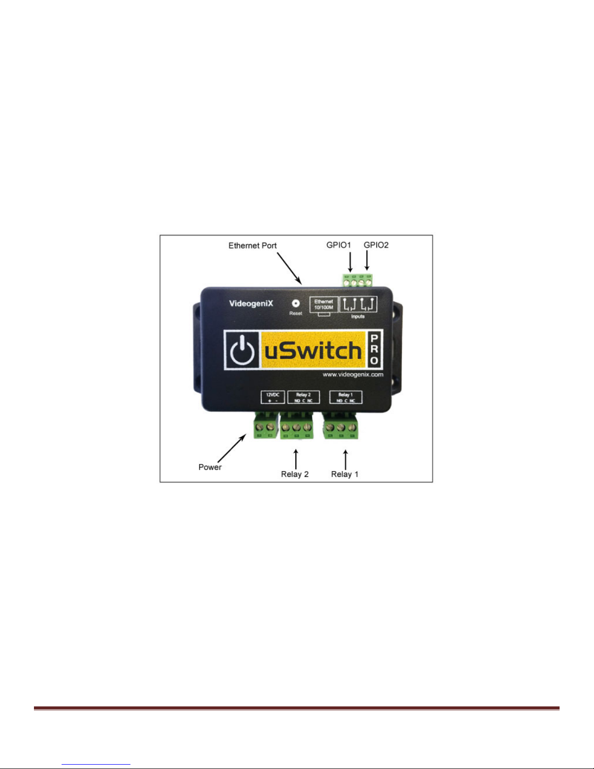
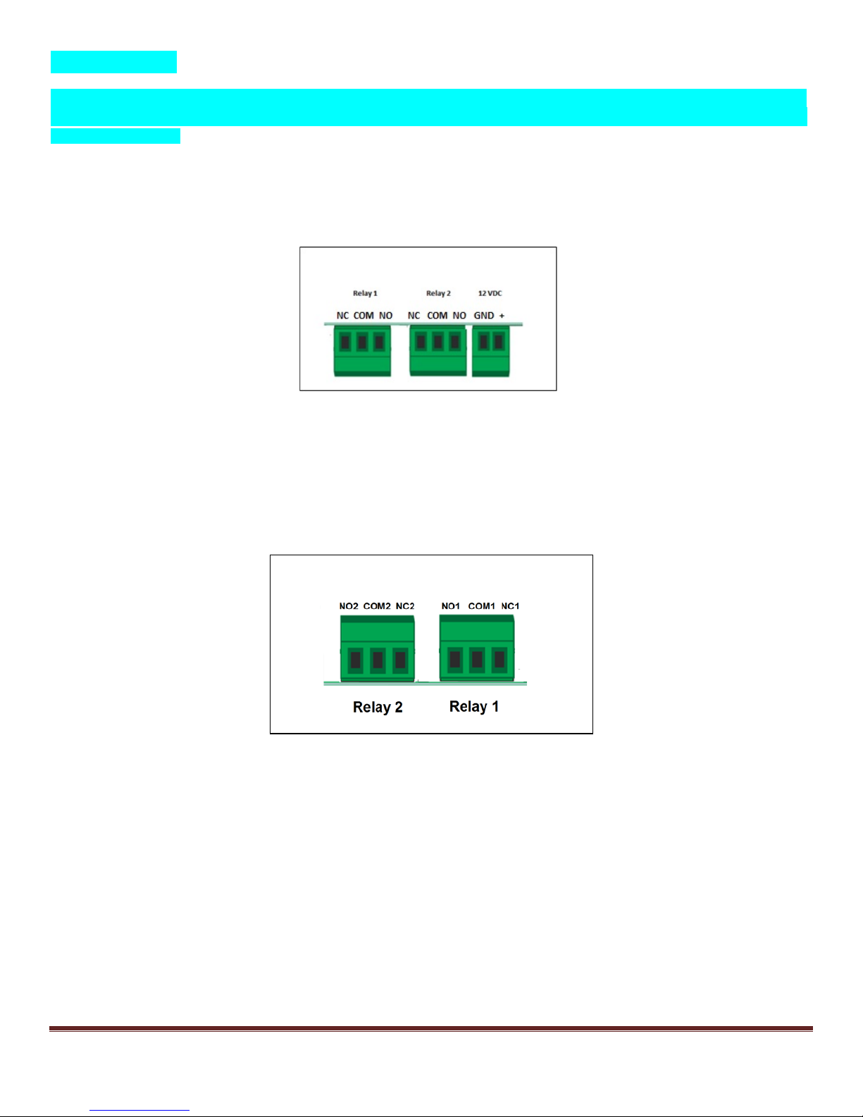
1. uSwitch can be connected to a DC power source in the range of 12-16Vdc . Connec t an appropriat e DC power
supply to the + and - Terminal s in F igure 1 (regulated power suppl y is rec ommended). The power supply s houl d
be rated to meet t he operating current of the uSwitch™ (s ee s pec ifi cat i ons for power requirement s i n appendi x
C). As shown in the photo, the positiv e terminal is the terminal closest to the outside unit edge; the negative
terminal is the terminal closest to relay connectors.
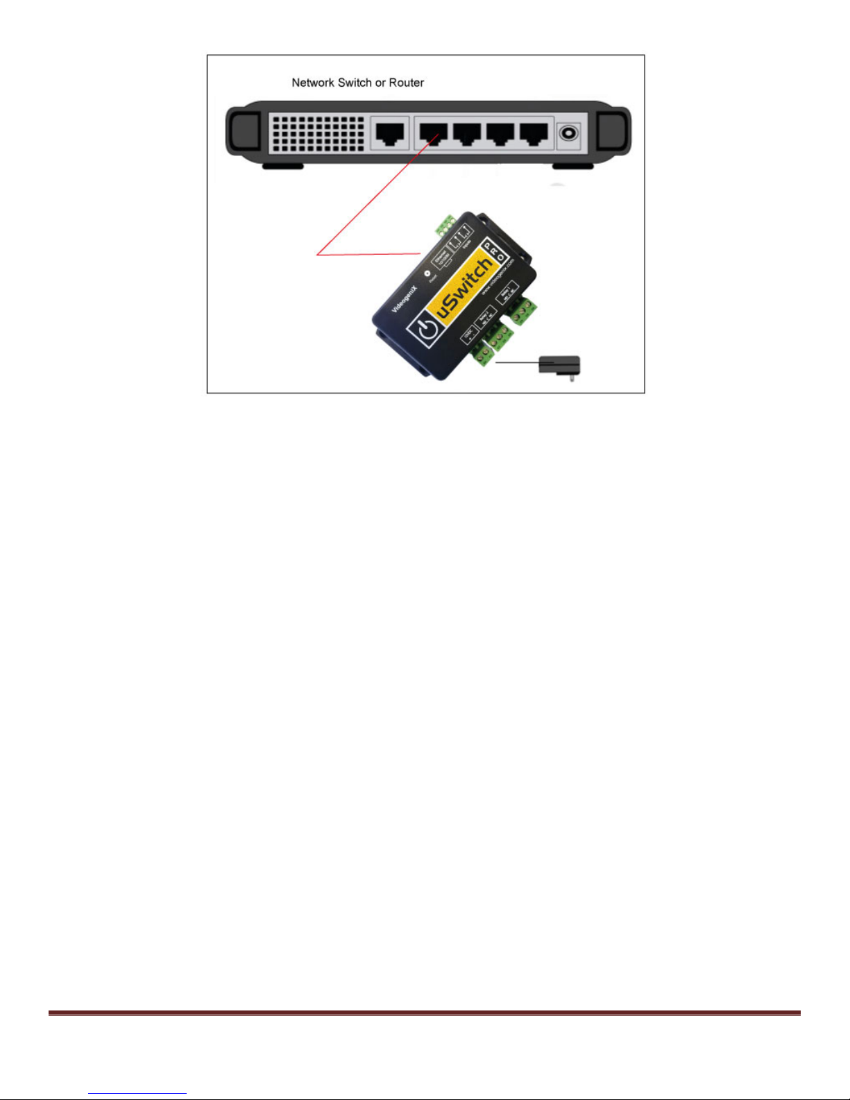
2. Connec t an Ethernet cabl e between the uSwitch Ethernet port and an Et hernet port on the net w ork sw itch/router.
Connec t a com puter to the network sw itch/rout er. (See diagram below). Alternat ivel y, you can connect the
uSwitch directly to the etherent port of your computer (c om puter m ust be on a 192.168.1.x xx subnet and both
should share the same gateway address and subnet mas k).
uS witch and uSwitchPro Inst allation and O perating Manual Page 6
Page 7
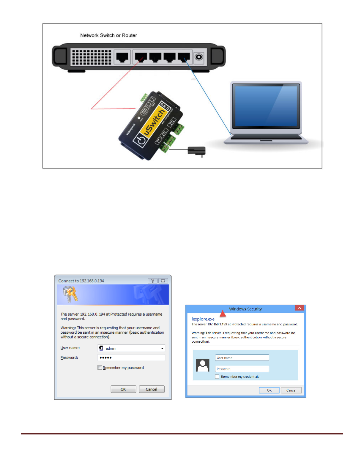
3. S et up a com puter on the same network/subnet as the uSwitch. To do this , s et the IP address of t he comput er to
192.168.1.x with subnet mask of 255.255.255.0 (x can be any unused address on that network 2-254) and
should not be i n a range designat ed for DHCP addresses by the rout er.
4. Connect to the uSwitch by entering its fac tory defaul t IP address (http:// 192.168.1.199)
into the address bar on
your computer’s browser. If the uSwitch is on a LAN with a router that has reserved the DH C P address of
‘192.168.1.199’ a conflict can occur. In this case either change the default address of the uSwitch upon
connection or remove ‘199’ from the DHCP reserved address space of the router. (Make sure the uSwitch’s
address is not blocked by any firewall you may be using).
5. If t his is the first time you are logging on t o the uS w itch from your com puter, a pas sword dialog box will appear
(see examples below). Enter “admin”, for bot h the Us er name and Password fields (al l lower case). Onc e logged
on passwords and user names can be changed from the Authorization Configuration Menu. For hi gher level
menus ‘admin’ is also the default password.
Windows Vista Windows 8
6. P ress “OK ” to accept the username and passw ord.
uS witch and uSwitchPro Inst allation and O perating Manual Page 7
Page 8
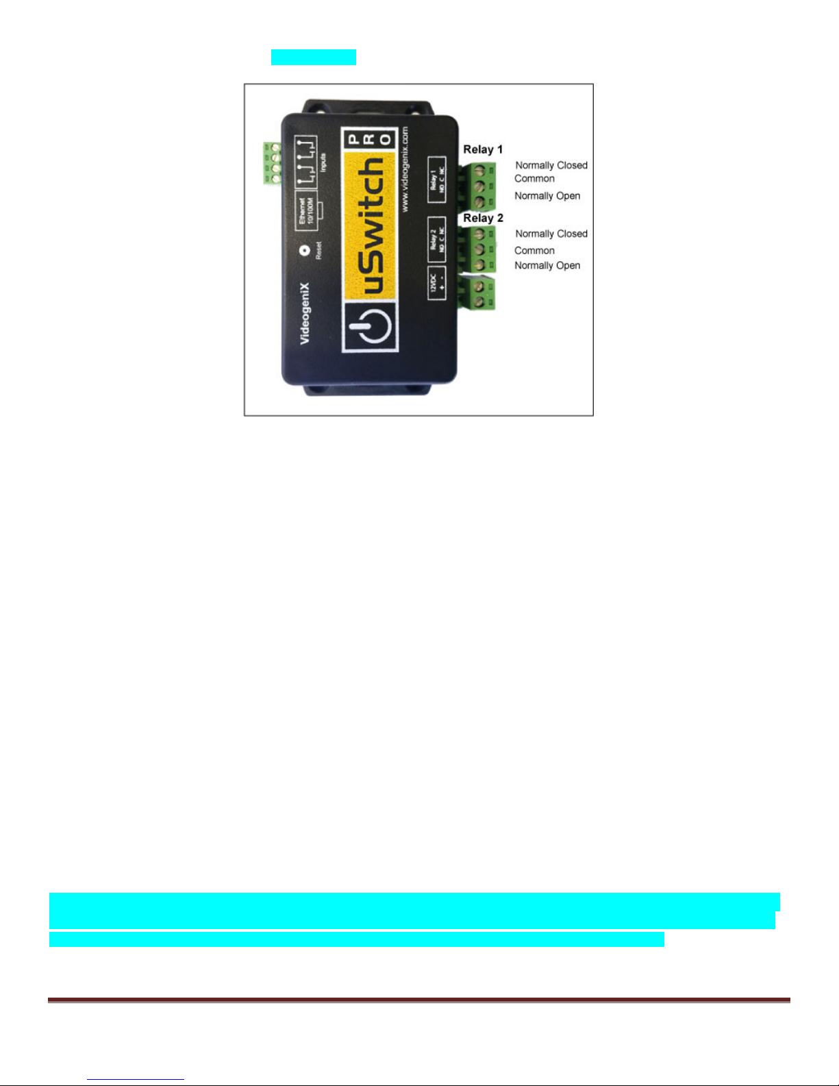
7. Connec t the relay contacts and or GPIOs as desired (refer to the diagram below for relay connections).
About uSwitch
uSwitch contains two electro-mec hanical relay s and a built in web server. The uSwitch’s web interface can be controlled
and/or moni tored over any IP network including priv ate networks, IP-based industrial control net works, and the Internet.
uSwitch c an be cont roll ed from a web browser or via a custom third party appli cation. Using standard CGI commands
uSwitch can operate stand-alone or can be cont rolled from a remote or l ocal web browser. It can be used to operate
access control dev ices, lights, pumps, v alves, locks, motors, etc.
Another feature of the uSwitch is, it can be programmed to automatically detec t device and network fail ure and restart
electroni c devic es that have frozen, or stopped func tioni ng properl y (even if c om m unication to uSwitch or device has been
completely lost). This m echanism is available to remotely reboot s ervers, com puters, cell and satellite modems, and other
devi ces one c an i magi ne - eit her LAN or WAN . uSwitch relay s can be wired in seri es wi th the power source of the device
and sw itch the pow er on and off manually. Another option is to connect uSwitch direct ly int o a devi ce’s reset circ uit. In
this configuration, uSwitch does not power down the devi ce and i niti ate a cold reboot, it simply forces a warm restart. Al l
reboot methods have different requirements in physical connection and setup. A fourth additional option is to wire a
uSwitch output to an external relay to control a phys ically isolated circ uit or one with a power load that exceeds the max
specifications of those inside the uSwitch.
uSwitch has a built-in Web Interface. You can access uSwitch by its IP address if you are c onnecting to it from the same
network or if you are on a remote WAN by the URL of the LAN and or the uSwitch’s assigned port (vi a port
forwarding/NAT). It can be accessed on networks with both stat ic and dynamic IP addresses (in the case of a dynamic IP
address a dynam ic IP client is required or a router supporting DDNS). The factory default IP address for uSwitch is:
192.168.1.199, its default netw ork port is 80 and the gateway is 192.168.1. 1.
uSwitchPro has two General Purpos e inputs (GP IOs). These GPIOs can be hooked up to sensors which can be linked to
the local relay and up to 16 remote relays, so that a change in sensor status can effectiv ely drive multiple remote relays.
For instance, a premise detection alert could lock down 9 doors and s et off 9 sirens across a cam pus.
uS witch and uSwitchPro Inst allation and O perating Manual Page 8
Page 9
Virtual Relays.
The uSwitchPro supports Virtual uSwitch control. With the creation of either v irtual buttons, or by using local GPIOs up to
eight (8) additional uSwi tches can be controlled either by a single local button or by the change in state of one of a sensor
attached to a GP IO..
Power Supply Connec tion
Connec t an appropriate DC power s upply to t he Vin+ and Gnd Terminals as shown bel ow (regul ated power supply
recomm ended). The power suppl y s hould be rated to meet the operati ng c urrent of uSwitch (specified in Appendix B).
Relay Connection
When connecting to the relay contacts make sure any current or future load wil l not exceed the load ratings for the relays
(per spec. in Appendix B).
Network Connection
Connect the uSw itch Ethernet port to a 10 Base-T or 100 B ase-T sw it ch, router or cel l modem/gat eway (per diagram
below). For configuration, uSwitch can also connect direc tly to the Ethernet port on a com puter usi ng a crossover/nul lmodem cable. Otherwi se, for connecti on through standard comm unication equipment a straight c able should be used.
uS witch and uSwitchPro Inst allation and O perating Manual Page 9
Page 10
uS witch and uSwitchPro Inst allation and O perating Manual Page 10
Page 11
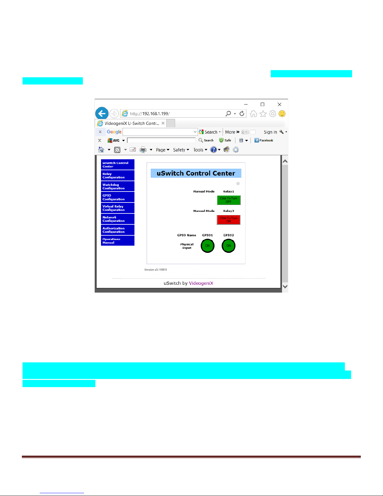
Control Center – Home Page
This is the main control and interface of uSwitch, called the “uSwitch Control Center”. The Cont rol Center appears w hen
the IP address or URL as signed to a uSwitch is entered into a browser from a dev ice that has access to that network.
The “Control Center” provi des manual relay control and status informat ion based on the various operati ng modes and
inputs (see operat ing m odes in uSwitch Control C enter Operati ng Modes secti on). Navigating between the uSwi tch
features is done by clicki ng on the blue menu buttons on the left side of any uSwitch page.. The menu options for t he
uSwitch are, uSwitch Control Center, Relay Configurat ion, W atchdog Configuration, GPIO Configuration, Virt ual
Relay Configuration, Netw ork Configuration, Authorizat ion Configuration, O perat ions Manual. There are two
levels of user operation. The Control C enter home sc reen i s acces s ibl e to anyone with the user name and password.
Configuration menus are only accessible to priv ileged users with a senior level password (default is ‘admin’)..
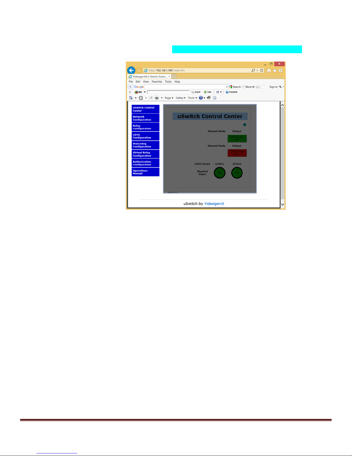
S elec ti ng the red “Clic k to Turn ON ” butt on on t he “Cont rol Cent er” page for a rel ay, energi zes the selected relay forcing a
normally closed (NC) contact to open or a normal ly open (NO ) contact t o close. The button’s color wil l simultaneously
change from green to red (unless these colors hav e been modi fied on the Relay Configuration menu) and the button’ s text
will change to “Click to Turn OFF” (unless “user assigned text” has been similarly modified).
“Relay1” and “Relay2” are fact ory default names assigned to the relays. These names can be changed by the user from
the Relay Configuration page (for exam pl e, “Front Door”, “Stair Lights”, etc.)
The Control Center als o includes the st ates of the inputs (GPIO1 and GPIO2 in a round i con). GPIO1 and GPIO2 are
default names assigned to these inputs. Custom colors, names, and state text for the GPIOs can be assigned from the
GPIO Configuration Page.
uS witch and uSwitchPro Inst allation and O perating Manual Page 11
Page 12
Menu Navigation
Navi gating between the uS witch menus is done by clicking on t he blue menu buttons on the left side of every page (each
configuration page has the ident ical menu choices avai lable). The menu options for the uSwitch are, uSw it ch Control
Center, Relay Configuration, Watchdog Configurat ion, G PIO Configuration, Virtual Relay Configurat ion, Network
Configuration, Authoriz ation Configurat ion and Operations Manual (t he Operations Manual is only available if a web
connection is available)
uSwit ch Control Ce nter Opera ting Modes
Control Center (Relay 1- Momentary Mode)
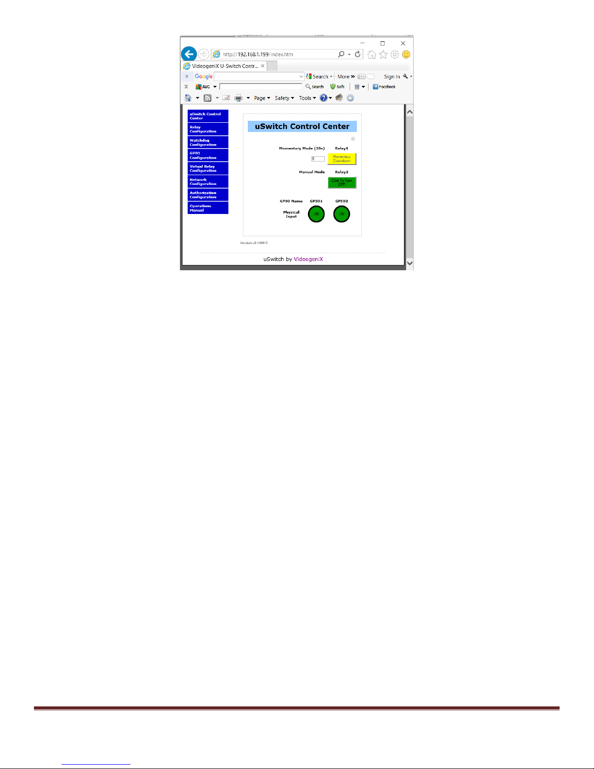
The image below s hows the Control Center wit h relay one configured as a twenty (20)second m om entary (or pulsed) rel ay
(a relay is confi gured into momentary mode from the Relay Configuration page). In t his case each time relay 1 button is
clicked, the relay changes its state, c ounts down to zero (currently 5) and then changes back to its starting state. To
change the relays initial state, temporari ly disable momentary mode by setti ng the m om entary t ime to zero (0) (from Rel ay
Configuration page), Then manually change the state of the relay (on the Control C enter page) to t he desired iinitial state.
Finally put the relay back into momentary mode by putting in a non-zero momentary time (from the Relay Configuration
page). Note: Onc e a moment ary countdown has started the push but ton relay cont rols are dis abled unti l countdown
completes (during countdown mode the colors of the relay flash between its current state and yellow).
uS witch and uSwitchPro Inst allation and O perating Manual Page 12
Page 13
Control Center (Relay1 Watchdog Mode, Startup Delay phase)
The image below s hows the Control Center wit h relay1 configured in Watchdog Mode (a relay is placed in watchdog
mode from the Relay Configuraton page). .A greyed out relay button indicates manual control is disabled when watchdog
mode has been turned on. Whenever a relay is in watchdog mode it cannot be manually controlled by a push button. The
screen below shows relay1 in Watchdog mode. On t he screen below thewatchdog feature has started t he init ial startup
countdown specified by the startup delay entry before testing for connectivity, currently 261 seconds remain before
watchdog mode becomes fully ac tive. A minimum recommended startup countdown time of five minutes (300 seconds) is
recommended.
uS witch and uSwitchPro Inst allation and O perating Manual Page 13
Page 14

uS witch and uSwitchPro Inst allation and O perating Manual Page 14
Page 15

Control Center ( Relay1 W atchdog Mode, Ping D elay phase)
The image below s hows the Control Center wit h relay1 configured in Watchdog Mode, during the, “Pi ng Delay” phase.
This i s the time interval between s uccess ive pings to the sam e UR L. A recommended ti m e of 90 seconds for the “ping
delay” setting is suggested. Note: During W atchdog Mode manual relay control is not allow ed so the relay control butt on
is grayed out.
uS witch and uSwitchPro Inst allation and O perating Manual Page 15
Page 16

C ontr o l C ent er (R ela y1 W a tc hdog Mo de, pinging pha s e)
The image below s hows the Control Center wit h Relay1 configured i n Watchdog Mode. In t his instanc e the uSw itch is
attempting to pi ng the URL “y ahoo.com ” assigned for relay1 to determine i f relay1 needs to be cycled. Also note this is
the third consecutive attempt to communicate with the URL, indicating the previous two attempts failed.
uS witch and uSwitchPro Inst allation and O perating Manual Page 16
Page 17

Control Center ( Relay1 W atchdog Mode, auto reboot countdown phase)
The image below s hows the Control Center wit h Relay1 configured i n Watchdog Mode. The uSwi tch automatically is
cyc ling the relay after fai ling to get res ponses from the URLs specifi ed in the W atchdog Configurat ion page for R elay1.
The screen shot below show s the reboot countdow n time remaining and will turn power back on to device when t he count
reaches 0. The am ount of time for the relay to be cycled i s as specified in the Relay Cycle Time field on the Watchdog
Configurat ion page. After a reboot of the device the W atchdog will again initi ate a start up delay countdown and hold off
watchdog tests unt il the device Startup period c omplet es ..
uS witch and uSwitchPro Inst allation and O perating Manual Page 17
Page 18

Control Center ( GPIO1 with counter enabled)
The image below s hows the Control Center wit h relay1 configured in W atchdog Mode and GPIO1 configured with the
“Enable Counting” field checked (if c ounting i s not enabled the running count fi eld and counter reset are not present on
this screen). The val ue 119 in the “Runni ng Count ” fi eld m eans, since the counter s tarti ng counting or was last reset by
the “Clear Counter” button (direc tly below), 119 full input state transit ions have oc curred on GP IO1. Clicki ng the Reset
button cl ears the counter.
uS witch and uSwitchPro Inst allation and O perating Manual Page 18
Page 19

Network Configuration Page
Network settings and control opt ions are modified from the Network Configurat ion page. If multiple uS witch devices are
used on the sam e network, connect only one at a tim e and configure t he IP address of each unit before connecting the
next uSwitch to the network. This prevents havi ng two netw ork devices on the same network with identical network
addresses (creat ing an IP address c onfl ict). It is a good idea to clear the Address Resolution Protocol Cac he (ARP ) each
time you swap uSwitch units on the same network. This is because each uSwitch has a factory default IP address
(192.168. 1.199) and if the cache is not cleared an IP address c onflic t could occur if two IP addresses are associated with
two different hardware MAC addresses from two differ ent uSwitch dev ices. To clear the ARP cache on a Wi ndows PC
type “arp –d inet addr” in a DOS/Windows command prompt window (“arp -d –a” as s uper user on Apple OSX). Onc e you
have changed network setti ngs on t he uSwitch you mus t c yc le power on the new uSwitch before the network sett ings will
take effect.
Y ou can use a proxy s erver to connect multiple uSwitch devi c es t o an outside network or t he internet by using a single
stati c or dynamic IP resol ved address. This can be done using most consum er or indus trial grade rout ers. If a proxy
server environment is to be set up, each uSwitch will not be accessible from the internet until the proxy server (router) is
confi gured wit h the uni que and spec i fic port number and IP addres s ass i gned t o each uSwitch on its loc al area network
(LAN). Thi s is a form of Netw ork Address Translation (NAT) also called port forwarding or virtual port addressing. T o
determine how to set up the prox y server for port forwarding (also call ed NA T) review the manual for the devi ce whi ch wi ll
act as the proxy server and as the gateway to the ot her network.
(Note: When multiple uSwitch devices are installed on the same local area network, each must hav e its own unique ‘LAN’
IP address. Every uS w itch comes with a fac tory default IP address of 192.168.1. 199. If mul tiple uSw itch devices are
used, assign a unique IP address to each, such as: 192.168.1.195, 192.168.1.196, 192.168.1.197, etc.). The following
Network Control Page shows the fact ory setti ngs on the standard uSwitch and uSwi tch products.
uS witch and uSwitchPro Inst allation and O perating Manual Page 19
Page 20

Host Na me
This configurabl e fiel d represents a user chosen name for your uSwitch. It will be used when reporting information from
thi s devic e and in any st atus logs . It is a vi rtual nam e for the c urrent uS wi tc h devi ce.
Enable DHCP
This check box should be selected when the user chooses to hav e a DHCP serv er automatically assign IPV4 addresses
to the uSwitch. DHCP is not recommended as DHCP as signed addresses are subject to change making it difficult to
permanently access a uSwitc h whose address c ould change at random points in time.
IP Address
This specifies the unique IPV4 address of t he uSwi tch on the LAN. (E ach uSwitch is factory configured w ith the default
stati c IPV 4 address of 192.168.1. 199). This stati c LAN address should be modified to be consistent with the LAN’s
subnet on whi ch it is to be installed.When using multiple uSwitch devices on the same LAN each uSwitch must have a
unique IPV4 address.
Gateway
This specifies the IP addres s of the gateway (t ypically router/cell modem) whi ch is responsibl e for creat ing the LAN and
connecting to other networks and or the WE B. If unknown, the Gatew ay address can be obtained from t he network
administrator. The Gateway is the LAN address of the dev ice that routes the internal LAN to an outside network (WAN) or
other net works . The factory default gatew ay s etti ng for t he uS witch i s 192.168.1.1. This must be the assigned address of
the device that routes the net w ork on which the uSwitch i s connected for uSwitch features t o funct ion correctl y. For
instance, pinging dev ices that are outside the l ocal are network when Auto Reboot mode is enabled will not work if the
correct Gateway address is not assigned..
Subnet Ma sk
The subnet mas k identi fi es a s pecifi c LAN’s pri vate addressing scheme on a TC P IP V4 network. This can typicall y be
obtained from the network administrator. The uSwitch default subnet mas k is set to 255.255.255. 0. E ach of these four,
three-digi t fields represent s an IPV 4 address fiel d. E ach of these fiel ds represents a byte worth of addressing (1-255).
A ny bi t positi ons in the address w ith a value of zero are ac ces sible on t he local subnet . Any bit positi ons with a value of 1
are fi xed (unchangeable) on the l ocal subnet. In the s ubnet mask, 255.255.255. 0, the firs t three IP byte address fiel ds
are fi xed and the last by te fiel d may vary from 1 to 255 (a value of 255 is equivalent t o 11111111 in binary).
HTTP Port
This specifies the HTT P port (for typical WEB access) used for outside communications to the uSwitch. By default, this
port is set to 80 (standard access port for HTT P dev ices). A unique port is required for each uSwitch or other such device
that is going to be accessed using a port address from outside the local network. In this case, each uSwitch device on the
sam e local area netw ork would be as signed a different port (for example 41, 42, 43, etc). W ith unique ports assigned to a
uSwitch, a router can forward all outside comm unication for a given device directly to a specific uSwi tch without the
outside network having any internal k now ledge of the addressing scheme on the LAN beyond the address of the gateway
to the LAN and the vi rtual port num ber (private IPV4 addresses are not access ible to the outside world/ cloud). Each
uS witch i s then accessed from the cl oud on its private network by entering the routabl e/resolvable IP address of the
gateway and the specific port assigned to the uSwit ch™. Any port (besides port 80) assigned to a uSwitch™ requires all
outside comm unications to that uSwitch t o referenc e it vi a it s assigned port. For ins tance, www.videogenix.com:42
devi ce on port 42) or www. M yHomeRouter:41.
(for a
T CP Por t
This specifies the T CP port for any internal or external TCP commands to the uSwitch used for outside communications to
the uSwitch. By default, this port is set to 9760 (standard port for TCP). This port does not need to be changed unless
your rem ote device spec ifies a port ot her than 9760 to thi s device IP address or If m ultiple uSwitches on the same subnet
are to be acces sed via TCP from outside t he network using only port numbers. With uni que ports assigned to a uSwitch,
a router can forward all outside communication for a given dev ice directly to a specific uSwitch without the outside
network havi ng any internal knowl edge of the addres sing sc hem e on the LAN beyond the address of the gateway to t he
LA N and the virt ual port number (pri vate IPV4 addresses are not accessible to the outside world/cloud). Each uSwitch is
then accessed from the cloud on its privat e network by entering t he routable/ resolvable IP address of the gat eway and the
specific port assigned to the uSwitch™.
Primar y DNS
uS witch and uSwitchPro Inst allation and O perating Manual Page 20
Page 21

This field is used by the uSwitch to resolv e outside URLs that may be included in the automatic reboot options or dev ice
firmware whose actual IP addresses are unknown i nside the LAN.
Secondary DNS
This secondary DNS (Domai n Name Server) is used by the uSwitch to resolv e outside URLs that may be included in the
automatic reboot options or device firmware whose actual IP addresses are unknown from the private network just in case
the pri m ary DNS is not available.
Auto Discovery
This checkbox should onl y be checked if y ou want to enable auto dis covery of a uSw itch on a netw ork. In t his mode a
uS witch periodically announces its presence on the network. To hide the uSwitch or silence it and diminish unnecess ary
network traffic thi s chec kbox should be unchecked. The default v alue is checked.
M AC Ad dre s s
This i s the physical address permanently as signed a given uS w itch. It cannot be modifi ed however it can be used to
verify which LAN IP address is connected to which uSwitch by executing either an arp -a command (from a wi ndows
computer), or when running the uS w itch disc overy utili ty.
To acces s a uSwitch remot ely from an outside network , WAN or the internet you wil l need to set up port forwarding (also
called NAT or Virt ual Port addres sing) on your router or gateway. You can set thi s up from your rout er’ s c onfiguration
page as follows:
1. A ssign a specific and unique port to each uSw itch from the Netw ork Configuration page of the uS w itch
2. Find the Port Forwarding/ Virtual Server/NAT configurat ion in your router and specify the unique port number
assigned to each uSwitch along with each uSwitch’s private IP address assigned in the step above.
3. If you are on a static IP line you may use a 3rd Party free DDNS provider to register a Domain N am e for your
Router (URL). Map your router to the free D D NS provider.
4. If the address assigned to your router by your ISP is dynamic (changes regularly) than you will need to set up the
dynam ic DNS page of your router to map the URL to a D ynami c IP Name Server (consult your rout er’s user
confi gurati on manual).
5. B rowse to your USwitch using the following protocol from a browser; http://myNetworksURL:myuSwitchPortNumber
(i.e . http://myHomeRouter:8000)
uS witch and uSwitchPro Inst allation and O perating Manual Page 21
Page 22

Relay Conf iguration Page
The Relay Configurat ion allows a user to customize how each relay is displayed, c ontroll ed and any configure s tart up
features . The Relay Configuration Page also provides an extra menu opt ion at the bott om ti tled “Force W at c hdog
Reboot”. This page is only accessible from wi thin the Rel ay Configuration page. It allows a user to bypass the c urrent
Watc hdog Cy cle and force a full reboot of a device. Normally in Reboot mode the user cannot force the rel ay output to
change states because the Wat chdog is in c ontrol of the R elay. By placing access to thi s option it prevents users without
access to the Relay Configuration from bypassing Watchdog Control.
Relay Configurat ion Page for uSwi tchPro
User Assigned Names
These two configurable fields represent user assigned names for each relay. Once modified all text identifying “Relay1” or
“Relay2” from the browser interface will be displayed with customer assigned names. Factory default names are Relay1
and Relay2.
Relay State On Text
This field specifi es the text assigned to t he relay butt on to be displayed when it is in the “On” st ate.
Relay State Off Text
This field specifi es the text assigned to t he relay butt on to be displayed when it is in the “Off” state.
uS witch and uSwitchPro Inst allation and O perating Manual Page 22
Relay Configurat ion Page for uS wit c h
Page 23

User Assigned Colors
This field specifi es whic h color is assigned to a relay for a given state. The choices are “RED/GREEN ” or “GREEN/ R ED”.
The colors may indicate different states depending on the physical wiring t o the uSwitch.
Power On State
This dropdown box configures the initial power on state of the relay when a uSwitch is first turned on. The options are
OFF, ON and LAST. (In W atchdog Mode the Relay Pow er On St ate Must be Programmed to “OF F”)
1. OFF - Relay is not energized on uSwitch power up.
2. ON - Relay is energized on uSwitch power up..
3. LAST - Relay is put in the state i t was in when on uSwitch power up..
Momentary (sec)
This timer field puts a relay int o moment ary (puls e) mode. W hen Moment ary is set to zero, the relay is latching. Clicking
on the relay’s control changes its state to the opposite state leaving it in that state (latched) indefinitely. A non-z ero value
in the Momentary field puts the rel ay in momentary/pulse mode. In this mode, each time the relay is clicked it changes its
state and retains in the new state for t he num ber of seconds specified in the Mom entary fi eld. Aft er the second counter
(on the display for t he relay) el apses the relay returns to i ts origi nal state. (Note, if wi ring a uSw itch in parallel with
another physical moment ary switch, such as a garage door opener, the relay m ust be put into momentary/pulse mode. If
not whenever uSwitch relay is closed the pre-existing switch will have its functionality blocked). A single relay cannot be
configured t o Momentary and any other Mode at the same time.
Ping Aut o Reboot
When checked the selected relay will act as an automatic watchdog reboot device and its state will be automatically
controll ed as specified in the settings from the Watchdog Configuration page. Li ke momentary m ode, watchdog mode,
is mutuall y exclusive). Manual operation of the relay is disabled in W atchdog mode. (In Ping Auto Reboot Mode the
P ower on State Must be Programmed to “OFF”).
Allows Master Control (applies to uSwitch a nd uS w i t chP r o )
When Allows Master Contr ol is checked the selected relay forfeits local control and only a remote uSwitch’s GPIO, or
vi rtual i nput can control t he relay. W hen a remote uS w itchPro is programmed to control this relay (on remote uSwitchP ro’s
GP IO Configurat ion page) the state of the relay wil l synchronize t o the GPIO (input) from the remote uSwi tchPro. This
enables a remote uSwitch virtual input or remote GPIO to sync multiple devices such as door locks on a campus from a
single action or uSwitch. uSw itchPros can be set up to remotel y control a relay on a standard or Pro uSwitch. This mode
is mutuall y exclusive to other m odes that are locally controlled.
Timed Reboot
The “Timed Reboot ” field can be programmed to eit her OF F, 12, 24, 36, or 48 hours. In Timed Reboot mode the relays
will automatically change their state after the speci fied ti me period expires and then ret urn to its original state after t he
number of seconds specified in the momentary field. A v alue must be specified in the momentary field because Tim ed
Reboots are always momentary. (there is also a test option for 30 seconds, since it is unreasonable to wait for 12 hours
to test this feature. Timed reboots are int ended to be used as a sec ondary reset strategy.
Sync to Local GPIO
This pul ldown menu ti es the respecti ve relay to t he respective GPIO. T he choices are “OFF, ANY, LOW, HIGH”. If “OFF”
is not selected than the state of the relay will synchronize with the specified state of the GPIO. When ANY is
specified the Relays output changes state with ev er y state change of the GPIO. When LOW is specified the
Relay will always track when the GPIO goes LOW however the relay remains under manual control if the GPIO
state is HIGH. When HIGH is specified the Relay will always track when the GP IO goes H IGH how ever the relay
remains under manual control if the GPIO state is LOW. T he relay will either be in the same state as the GPIO
when it is tracking or the opposite stat e of the GPIO depending on the “Sync Inverts G PIO” fiel d.
uS witch and uSwitchPro Inst allation and O perating Manual Page 23
Page 24

Sync Inverts G PIO
If th is field is not checked and Sync to Local GPIO is not set to “OFF” the relay state will match whatever the GPIO state is
when it is synchronizing. If “Sync Inverts GPIO is not checkedand Sync to Local GPIO i s anythi ng but “OFF” the Rel ay
state will be the opposite st ate of the GPIO.
Link Buttons Toge t her
This checkbox is used t o assign all the properties for button 1 t o button 2 and li nk them together. When relay butt ons are
li nked, whenever B utton1 is manual ly pushed both rel ays transit ion their st ates simultaneously (note: depending on the
initial states they can both transition to the same state or opposite states). If timer mode is specified along with linking,
both buttons use Relay1’s timing options.
Force Watchdog Reboot
This Page is accessible only from the menu on the Relay Configurat ion page. It enables a user to force a R elay in “PingAuto-Reboot Mode” to reboot. Only users with priv ileges to access the Relay Configurat ion page wi ll be able to forc e a
Watc hdog Relay Reboot. The screen brings up all relays and enables the user to c lick on any relay and change its state
or cycle t he rel ay if in Ping-Auto-Reboot mode. How ever certain relay configurations or states sti ll w ill not allow the relay
to be forced to a different state (i.e. relays that are synced to a GPIO, slaves to another uSwitch, or in Ping-Auto-Reboot
mode during a Reboot).
Force Wat chdog Reboot Page
uS witch and uSwitchPro Inst allation and O perating Manual Page 24
Page 25

uS witch and uSwitchPro Inst allation and O perating Manual Page 25
Page 26

GP IO C o nf igur at io n Pa ge ( uSwitc hP ro o nly)
The GPIO Configuration allows a user t o cus tomize how eac h G PIO is displayed, control led and its control features.
User Assigned Names
These two configurable fields represent user assigned names for each GPIO relay. Once modified all text identifying
GP IO1 and G PIO2 from the browser interfac e will be displayed wit h custom er assigned names.
GPIO Hig h State Text
This field specifi es the text assigned to t he G PIO when it is in the high state.
GP IO Low Stat e Text
This field specifi es the text assigned to t he G PIO when it is in the low state.
User Assigned Colors
This field indicates the text displ ayed on the Control Center when the GPIO is in ei ther high stat e or low stat e. The
choices from the selection box are “ON/OFF”, “O PEN/CLOSED”, “LOCK/UNLOCK”,”START/ST OP”.
Enable Counting
When checked the internal logging software keeps a running count of full transitions on the associated GPIO and displays
it in t he “running count” field on the Cont rol Center (home) page. Each time the GPIO goes through a full transition the
counter increments. To reset a counter t o zero click on the “Clear C ounter” but ton on the Control Center page.
uS witch and uSwitchPro Inst allation and O perating Manual Page 26
Page 27

Watchdog Configuration Page
The Auto Reboot Ping feature allows uSwitch to automatically detect failed equipment and reboot or res tart i t without
human intervention. You may set one to three IP addresses or URLs to be periodically tested for each relay. If the uSwitch
determines a communi cation problem exists bet w een any or all of the specified devi ces , the selected relay will
automaticall y cycle, swit ching power on and off t o reboot a device or devices w hose power has been wired across the
relay.
The Watchdog feature has been successfully deployed with: IP cameras, kiosks, web signs, cellular routers, Servers, DSL
and cable modems, RTUs, control sensors, a variety of Smart Grid technologies , etc.
The foll owing paramet ers are effecti ve only w hen uSw it ch i s s et to Auto Reboot Ping mode (in the Relay Configurat ion
page).
uS witch and uSwitchPro Inst allation and O perating Manual Page 27
Page 28

External Heartbeat
This checkbox enables the watchdog to work i n network CloakM ode™. In this mode the uSwi tch watchdog works from an
external message embedded in a TCP s tring sent to t he uSwi tch from a remotely networked devi ce (i ts heartbeat ). If a
uSwitch fails to receive the cloaked message based on the parameters specifi ed than a reboot oc curs. If not c heck ed the
uS witch wi ll do all its watchdog testing based on the IP addresses or URLs specifi ed in the URLs to ping field. Note, for a
uSwitch t o be placed in wat chdog the Ping Auto Reboot checkbox on t he Relay Configuration Page must be
checked.
URLs to Ping (any Relay)
These three (3) fields contain the IP addresses, or URLs of remote or local devices or servers that uSwitch will ping to test
for communi c ati on or devic e problems. These m ay include the s tatic IP address or remote IP of devices that will be
tested (router, computer, Kiosk, net work camera, or a device on the opposite si de of a comm unications l ink). This is ideal
for restarting communications dev ices such as CSU/DSUs/RTUs, cameras, satellite modems, routers, re-closures, power
meters etc., after they have locked up.
Ver ify all URLs
The Verify all URLs checkbox specifies whether response from pings to all URLs (specified in URLs to Ping) is requi red to
determine an operat ional failure, or i f a fai lure from any single URL is an operati onal failure.
Max Ping Failures
If no pi ng responses are recei ved for Max Pi ng (consecutive) failures than the selected relay will be cycl ed (forci ng a
power cycle on any connected dev ice). A ping failure occurs if any single device fails to respond if Verify all URLs is
check ed, or w hen no devices respond if Verify all U RLs is not checked.
Max Reboo t Attem p ts
After “Max Reboot Attempts” without a successful communication the uSwitch™ exits “Auto Reboot” normal mode and
enters ”Fault m ode”. (During “Faul t mode” the uSwitch™ s tops cyc ling the relay to the attac hed devi ce for the specifi ed
Fault Mode Time. The Fault Mode cy cle prevent s c ontinuous power cy cling on a device after detecting that a normal
power cy cle is not w orking t o bring the device(s) back online.
Mode Start Delay
When uSw itch is first powered on, or aft er a reboot occurs, the uSwi tch will wait “Start Delay” time before restarting a new
watchdog testing cycle. This start delay giv es a newly restarted dev ice normal setup time to fully establish its connections
to ext ernal devic es before resumi ng watc hdog tes ti ng. The recommended m ini mum and fac tory defaul t for t his field is five
(5) minutes. (Certain devices such as cellular modems will not work if not given time to re-establish connections with the
ISP and WAN. This can take up to ten minutes).
Time Between Pings
This i s the frequency (in s econds ) bet w een cons ecutive device ping attempts t o the sam e URL. This field prevents ping
flooding the network and allows the watchdog algori thm to success ful ly work in situat ions where the network or its
connections are imperfect. (The recomm ended minimum time between Pings is ninety (90) seconds).
Relay Cycle T ime
This is the time period that the uSwitch switches the relay off before switching it back on (giving a device time to hav e a
cl ean power s hut down and re-pow er). (The recomm ended mi nimum Relay Cycle T ime is five (5) seconds)
Period be f or e Retry on Fault
This i s the time that uSwitch wi ll remain in “Device Fault Mode” before returning to “Auto Reboot Mode” to re-attempt
device startup after the specified Max Reboot Attempt c ons ec uti ve failures have occurred. This feature prevent s the
continuous cyc ling of power on a device that may not have a power cy cle curable comm unication failure. The
recommended minimum Period before Retry on Fault is four (4) hours.
uS witch and uSwitchPro Inst allation and O perating Manual Page 28
Page 29

Vir tual Rela y Configuratio n Page
The V irtual Relay Configuration allows a user t o create addit ional control buttons on the Control Center page of a
uS witchPro to control relays that are on other uSwitch(s) or uSwi tchPro(s) across the LA N. This feature is us eful to have
a single button control mul tiple different relay s s imultaneously across a network with the touch of a single button (i.e. for a
multi-door loc k down).
This pul ldown fiel d provi des four opt ions: None, Button1, Relay1, GP IO . These fields select whether a virtual relay is
created on the “Cont rol Center” screen and i f so what drives the remote uSwitch’s Relays. If Button1 is sel ected a vi rtual
button is created on the Relay Control C enter and this button cont rols all remote uSwitches as specified. If Relay1 is
selected than the state of Relay1 on this uSwitch drives all other uSwitches specified. If GPIO is specified than the state
of the GPIO specified will be used to driv e the state of all remote uSwitch Relays.
User Assigned Names
These two configurable fields represent user assigned names for each ”v irtual relay” button. Once modified all text
identifying “Remote1” or “Remote2” from the browser interface will be displayed with the assigned names
Virtual On State Text
This field specifi es the text assigned to t he virtual relay button to be di splayed when it is in t he “On” state.
Virtual Off State Text
This field specifi es the text assigned to t he virtual relay button to be di splayed when it is in t he “Off” stat e.
uS witch and uSwitchPro Inst allation and O perating Manual Page 29
Page 30

User Assigned Colors
This field specifi es whic h color is assigned to a “virtual” relay for its gi ven state. The choi ces are “RED /GREEN ” or
“GRE EN/RED ”. The c olors may indi cate different states depending on the physical wi ring to t he uSwi tch.
Momentary (sec)
This timer field puts a “vi rtual” relay int o momentary (pulse) m ode. When Momentary is set to zero, the relay is latching.
Clicking on the relay’s control changes its state to the opposite state leav ing it in that state (latched) indefinitely. A nonzero value in t he Momentary field puts the relay in moment ary/pulse mode. In this mode, each time the relay is clicked it
changes its state only for the number of seconds specified by the Momentary field.
Control Slave Relay(s)
This selecti on box determines which remote relay or relays on the remote uSwitch(s) or uSwitchPro(s) will be driv en.
Choices are NONE, 1, 2 or ALL. This is a useful feature if a single HTML button, GPIO or Relay is desired to energize or
de-energize multiple relays across the network from a single manual action vi a a vi rtual button, or automatically via a
sensor attached to an input on one of the GP IOs.
Slave Relay Start IP
When Control Slave R elay(s) box is set to a selection ot her than “NONE”, this numeric IP address (such as 192.168.2.17)
is the IP address of anot her uSwitch on this or an outside addressable network whose s elected relay or relays are driven
by the virtual relay Button, GPIO or Relay specified in the “Source of Cont rol” field on this page. I f the IP address
specified is not routable from thi s uSwitch’s network (becaus e of a firewall or addressing li m itat ion) this feature wi ll not
drive the relay specifi ed in the Slave R elay Start IP fi eld.
Consecutive Relays
This box all ow s the entry of the single IP address in the Slave Relay’s Start IP fiel d (above) to extend to multiple
consecutiv e IP addressed uSwitches. This features enables multiple uSwitch control; however, it requires uSwitches that
are dri ven remotely by a single “virtual” control to have consec utive IP addresses. T he number in this box is the number
of consecutiv ely addressed uSwitch relays beginning with the address specified by “Slave Relay Start IP” to be controlled
by the singl e “virtual” c ontrol bei ng identi fied (t his can be a value of 1 to 4).
Slave Relay’s End IP
This automatically generated informational field shows the last IP address for the last uSwitch to be driv en by the “virtual”
control button. It is calculated by adding the “Consecutiv e Relays” count to the “Slave Relay Start IP” address.
Link Buttons T oge t her
This checkbox is only active when both Vi rtual Relays are configured as “Buttons” in the “Source of Control” pull down.
When checked it results in eliminating the second virtual button on the uSwitch Control Center page and ties all remotely
driven relays from both fields to a single virt ual button. (Link ing Buttons Together enables a si ngle push button to control
up to Eight (8) remote uSwi tches and a single or all of their relays from a singl e “Virtual Control”).
uS witch and uSwitchPro Inst allation and O perating Manual Page 30
Page 31

Authorization Configuration Page
The Authorization Configuration Page is used to change uSwitch access passwords. A password is required on initial
logi n to uSwitch. Passwords may be up to fi ft een (15) characters and numbers. We recommend difficult passwords of at
least eight (8) characters including both letters and numerals.
To change user passwords or administrat or passwords all fields on thi s page mus t be ent ered com pletel y. Once access
is provided to t he Authorization C onfi guration screen the privileged user can change t he uSwi tch’s “Username” field, and
the “User Passw ord” whic h provides ac ces s for the Control C enter. The user must also, either re-ent er the existing
A dm inistrator password, or provide a new Admi nistrator pass w ord (t he adm inistrator passw ord provides access to all
uS wit c h configurat ion opt ions and s houl d be gi ven out dis c rimi natel y ).
Security Notes
uS witch i s an extremely secure networking control device. It does not support term inal or file trans fer programs
(T FT P/FT P). This means it is not possibl e for s om eone to ‘break i n’ to it and acc ess other devices on your l ocal network.
uS witch does not support remote firmware updates so it is not poss ible for s om eone to remotely ins tall malicious software.
A s with any device to be ins talled on a network, t here are som e securit y precauti ons that should be observed. If uSwi tch
is installed on the Internet, it is recommended that passwords be secure (at least eight (8) characters in length with a
combination of upper case letters, lower case letters, and numbers). For additional security, a f irewall may be used to
limit access only to selected IP addresses. Another option may be to set up a Virtual Priv ate Network (VPN) between the
network where uSwitch resides and the client machine (web browser, second uSwitch, etc.) .
uS witch and uSwitchPro Inst allation and O perating Manual Page 31
Page 32

uSwitch/uSwitchPro Board Schematic
The GPIO
uSwitchPro
contacts are
only on the
uS witch and uSwitchPro Inst allation and O perating Manual Page 32
Page 33

Configurations
Access Control to Electroni c Door Strike
The foll owing i s a confi guration w here uSwi t ch is used to provide access control. When connecting to door strikes a
reverse-bias diode is rec om m ended. In this exam ple, a reverse-bias diode is connected in parallel with the lock to prot ect
the rel ay c ontacts from the i nductive kick back that c an occ ur when the lock is switched. A variety of diodes is available
and can be ordered either online or direct ly from us. (For AC door acc ess control no diode is necessary, for DC powered
devi ces a 60V p/p diode is recommended).
Driv ing mult iple uSwit ch Re lays f rom a single uSwitch GPIO or Virt ual Button
In addition to a physical push butt on driving the local relay on the sam e uSw itch either that push button or the but ton
generated on the Control C enter page, or a virt ual button can be created t o command a relay on a remote uS w itch. O nce
setup, pushing that button will drive all relays in its configuration as specified by the virtual or physical button. Each
uSwitch can be programmed to drive up to eight separate relays on the network. Additionally, if a relay output i s
hardwired into its own, or another uSwitch’s GPIO it can in turn be used to drive an additional 8 relays. By daisy chaining
uS witches in thi s manner a s ingle GPIO can dri ve an unlimited number of relay s on other uSwitches.
uS witch and uSwitchPro Inst allation and O perating Manual Page 33
Page 34

C o nnec t i ng t o High Power devices (such as Motors, etc)
Connection to an External Relay
For loads great er than t hose rated for the uSwit c h’s int ernal relays , or when connec t ed to devi ces wi th high inrus h or peak
current surge an external relay should be used with the uSwitch triggering the relay . The ill ustration below shows how a
high current m otor or other high load device can be control led using by wiring to an external relay . A variety of external
relays is av ailable and can be ordered either online or directly fr om Videogenix.
When relays switch inductiv e loads such as motors, transformers, relays, etc., electricity will arc across the internal relay
contacts each time the contacts open. Over time this causes wear on the relay contact s which can shorten their life s pan.
When switching a high inducti ve load, it is recom m ended that simple relay contact protection devices be used. To be
econom ically feasible uSwitch cannot provide relay prot ection for al l possible loads.
For applications with excessiv e loads, the following diagram s how s a relay contact protec tion circ uit for DC and for AC
appli cations. For component val ues required to provide sufficient contact protection for a speci fic appli cation, consult the
application reference. Note: for DC circuits a diode is used and for AC circuits an RC circuit across the load can be used.
uS witch and uSwitchPro Inst allation and O perating Manual Page 34
Page 35

Hard Wired Network Conn ect i on
Using standard Ethernet cabling, connect uSwitch’s Ethernet port t o a 10 Bas e T or 10/100 Base T Ethernet connecti on
such as a network switch, router or cellular mode. To connect directly to a computer, use a “crossover/Null Modem” cable.
For connec t ion to a router or s wit c h, a s t andard “st raight -through” cable is recommended.
uS witch and uSwitchPro Inst allation and O perating Manual Page 35
Page 36

Wire d Network Connect ion
Wire less Network Connect ion
Wireless Network Connection
To operate uSw itch in a w ireles s network environment, connect the uSwitch’s E thernet port to a wireless repeater or
bridge. The wireles s bridge i n t urn connec t s t o t he wireless network. The wireless Ethernet Bridge or router must be
properly s et up for the wireless network first. This informat ion is contained i n the E nd User documentation for the wireles s
network ing devi ce. A variet y of wi reles s repeat ers i s availabl e and c an be ordered eit her online or from VideogeniX.
uS witch and uSwitchPro Inst allation and O perating Manual Page 36
Page 37

T h e A-Plug Universal 110VAC uSwi tch Adapter
The A-Plug is designed to easily snap into uS witch or uSwit chPro c onverting its t w o rel ay outputs into two 110VA C
outlets. There is no need for wiring or spl ic i ng with A-Plug. The A-Plug powers the uSwitch and receiv es its power directly
from any wall outlet to which it is plugged in.
Troubleshooting:
B efore returning a device t est the power input trans former to uSwitch. This can easily be done by swapping out with a
know n working power transformer.
uS witch and uSwitchPro Inst allation and O perating Manual Page 37
Page 38

Appe ndi x A: F ac t o ry Default S etti ngs
In the event that the IP address or passw ords are forgot ten and you c annot log in to uSwi tch, you can reset uSwi tch to it s
factory default s etti ngs. With power press the reset butt on for about five (5) seconds (you should feel or hear the reset pin
click). After approximately fiv e (5) seconds, release the reset button. Wait thirty (30) seconds then cycle power on
uSwitch. At this point all settings should be res tored to fact ory default s etti ngs (shown below)
Network Configuration:
Host Name: U-SWITCH
Enable DHCP : unchecked
IP Addres s : 192.168.1.199
Gateway: 192.168.1.1
Subnet Mask 255.255.255.0
HTTP Port: 80
Primary DNS 8.8.4.4
Sec ondary DNS 8.8.8.8
Auto Disc overy: checked
MAC Address : Predefined at Factory (non-configurable)
Rel ay C onfi gura tion :
User Ass igned Nam e Relay1/Relay2
User Ass igned T ext On (Off)
User Ass igned C olors Red/Green
Power Up State: Last ( s ets relay t o retur n to previous s tat e after eac h uS wit c h power c ycle)
Momentary(sec): 0 ( non-momentary)
Ping Auto R eboot: unchecked
Allows Master C ontr ol: unchecked
Sync to Local GPIO unchecked
Sync Inverts GPIO unchecked
Timed R eboot ( hours ) Off
Link B uttons Together : unchecked
GPIO Configuration :
User Assigned Name GPIO1/GPIO/2
User Assigned T ext On (Off)
User Assigned Colors: Red/Green
E nable Counting unchecked
Watch dog Confi gu r at i on :
URLs to Ping
External Heartbeat: unchecked
URL Primary: 8.8.8.8
URL Sec ondary: 4.2.2.2
URL Tertiary 192.168.0.1
Verify All UR Ls: unchecked
Auto Reboot Counters
Max Ping Failures : 3
Max Reboot Attem pts 3
Auto Reboot Timers
Mode Star t Delay: 5 m in, 0 sec onds
Time Between Pings: 1 m in, 30 sec onds
Relay Cycle Time: 5 Seconds
Fault Mode Timer
Period B efore R etry on Fault : 4 hours, 0 minutes , 0 sec onds
Authorizat ion Configuration
Username: “admin”
Us er Password: “admin”
Admin Password: “admin”
uS witch and uSwitchPro Inst allation and O perating Manual Page 38
Page 39

Appe ndi x B: S pe ci fica t i o ns
AC
Relay Capac it y: 7.5 A Max at 105-125 VAC, 5 A Max at 210-240 VAC
Power Requirements:
Model uSwi tch
Voltage: 12VDC – 24VDC%
Model uSwi tch, uSwitchPro
Standby Curr ent
(Relays OFF) - 58mA
One Relay on - 92mA
Both Relays on - 126mA
Relay Ratings:
Rated Carrying Current: 5A @ 125VAC, 5A @ 250VAC, 10A @ 24VDC
Max Current: 10A
Max Voltage: 240VAC, 110 VDC
Relay Performance
Relay Control Options: ON/OFF, Pulsed, Automatic, Momentary
Contact Resistance <50m ohms (initial v alue)
Contact Material: Ag alloy
Max Switching Voltage: 240VAC, 110VDC
Max Switching Current 20A
Mec hanic al life (rated l oad) 10,000, 000 ops.
E lec tri cal li fe (rated l oad) 100,000 ops .
Networking:
Network: 10/100 Base-T, IP v4
Network Setup: static IP address assignment, DHCP, HTT P port selectable
Network Connector: 8-pi n RJ-45 soc k et
Connectors:
Power/Input: 2-position, removable terminal strip, 3.81mm terminal spacing
Relays: 3-positi on (Normally Closed, Normall y Open, Common) removabl e termi nal, 3. 81mm terminal s pacing
Ethernet: 8-pin RJ-45 soc ket
GPIOs 4-position, remov able terminal strip, 3.0mm terminal spacing
LED Indicators: (on E thernet j ack )
-Network linked
-Network activity
Physical:
MTBF 360,000 hour s
Temper ature 0 – 50 degrees C (-30C, + 80C)
S ize: .4.2 in (106 mm ) l ong, 2.15 in (55mm) wide, 1.0 in (25 m m ) deep
Weight: 4.3 oz. (122 grams)
Password Settings:
P assw ord protec tion on setup page: Yes
Password protection on configuration pages: Yes
Other:
Virtual Control: Yes
Control Linking: Yes
uS witch and uSwitchPro Inst allation and O perating Manual Page 39
Page 40

uS witch and uSwitchPro Inst allation and O perating Manual Page 40
Page 41

Warranty
VideogeniX warrants this
in material and workmanship for a period of One Year from the date of initial purchase. If the product should prove defective
within that period, Seller will repair or replace the product at its sole discretion.
This warranty is extended to the original purchaser of the equipment only. Call VideogeniX Technical service to receive a
Return Materials Authorization (RMA) Number prior to sending any equipment back for repair. Include all cables, power
supplies and proof of purchase with shipment. For warranty service or repair, return to VideogeniX at 1425 Beacon St,
Brookline, MA. Purchaser shall prepay all charges for shipping to VideogeniX. VideogeniX. will pay the shipping charges to
return the product to the purchaser as long as the product is shipped within the United States. If the product is shipped
outside of the United States, the purchaser shall pay all shipping charges, duties, and taxes.
THIS WARRANTY DOES NOT APPLY TO NORMAL WEAR OR TO DAMAGE RESULTING FROM ACCIDENT,
IMPROPER USE, MISUSE, UNAUTHORIZED REPAIR, TAMPERING, MODIFICATION, IMPROPER CONNECTION,
OPERATION OUTSIDE THE ENVIRONMENTAL OR ELECTRICAL SPECIFICATIONS, ABUSE OR NEGLECT.
SELLER MAKES NO EXPRESS WARRANTIES OTHER THAN THE WARRANTY EXPRESSLY SET FORTH
HEREIN. EXCEPT TO THE EXTENT PROHIBITED BY LAW, ALL IMPLIED WARRANTIES, INCLUDING ALL
WARRANTIES OF MERCHANT ABILITY OR FITNESS FOR ANY PURPOSE ARE LIMITED TO THE WARRANTY
PERIOD SET FORTH ABOVE; AND THIS WARRANTY EXPRESSLY EXCLUDES ALL INCIDENTAL AND
CONSEQUENTIAL DAMAGES.
Limitation
Further, t he warrant y does not c over Act s of G od, s uch as fire, flood, hurri canes, and tornadoes. This warranty does not
co ver damage
business profit, business interruption, loss of data, and t he like) arising out of the use or
NO CIRCUMSTANCE S WILL THE LIABILITY OF VIDEOGENIX T O T HE PURCHASER OR ANY OT HER PART Y
EXCEED THE
other warranty is expressed or implied. VideogeniX specifically
fit ness for particular purpose. S om e
incidental
to property, equipm ent, direct, indirect, consequential, or i ncidental damage (including damage for loss of
ORIGINAL PURCHASE PRICE OF T HE PRODUCT , REGARDLESS OF THE FORM OF T HE CLAIM. No
damage.
product, if used in accordance with all manufacturers’ specification, to be free from original defects
misuse of this product. UNDER
disclaims the implied warranties or merchantability and
juri sdictions may not allow the ex clusion of limitat ion of li ability for c onsequential or
Notice:
Changes or modification not expressly approved by the part y responsible for c om pliance could void t he user’s authority t o
operate t he equipment.
uS witch and uSwitchPro Inst allation and O perating Manual Page 41
Page 42

Trademark and Copyright Information
This document is Copyrighted ©2015 by VideogeniX, Inc. All rights reserved. VideogeniX and uSwi tch and uSwitchPro
are Trademarks of VideogeniX. A ll parts of this product and design inc luding but not limited to firmware, hardware design,
Schematics, PCB layout, concept, graphics, user’s manual, etc., are property of VideogeniX , Inc. ©2015. uSwitch may not
be opened, disassembled, copied, or reverse engi neered w ithout expl icit writ ten agreements to do so.
No part of this manual may be reproduced or transmitted in any form or by any means, electronic or mechanical, including
photocopying, scanning, for any purpose other than the personal use by the purchaser of this product. VideogeiX Inc.,
assumes no responsibility for any mistakes or errors in this document.
VideogeniX , Inc. is not liable for any damages or losses including direct, indirect, special, incidental, or consequential
damages or losses ari sing from ei ther the use of any i nformation contained wi thin this m anual or t he use of any products
or services referenc ed in this manual.
V ideogeniX, Inc. reserves the ri ght to change any product’ s features, spec ific ations, documentation, warranties, fee
schedules, and conditions at any time and without notice.
uS witch and uSwitchPro Inst allation and O perating Manual Page 42
Page 43

VideogeniX
1423 Beacon Street
Brookline, MA 02446
Copyright © 2015 VideogeniX, Inc.
617-731-5550
www.videogenix.com
 Loading...