

Page 1
XTO / XTO-IP ALARM PANEL SERIES
INSTALLATION MANUAL
DOC. - REF. 230-XTO-IP
MODIF. DATE :
SEPTEMBER
2018
FIRMWARE VERSION : XLP.04.04.00.XXX AND
LATER
1
Page 2

XTO /
XTO-IP Alarm panel
INSTALLATION MANUAL
De
scription
The XTO / XTO-iP is a fully wireless alarm system. It is powered by standalone Lithium batteries.
This panel has been designed for outdoor installations, with its weatherproof casing and extended operating
temperature range.
With the Motion Viewers™ and Videofied® range of products, the XTO-iP panel provides video verification in case
of intrusion.
Technology
The XTO-iP alarm panel, like all Videofied devices, uses the S2View® patented technology. Which is an interactive
wireless and AES encrypted technology ensuring signal integrity and optimal security.
The reliability of the signal is guaranteed thanks to the two-way radio frequency transmissions with all the peripherals
of the Videofied® product line.
The integrated antennas allow the system to be totally wireless, thus preventing from the system beeing inelegant
and cumbersome, and eliminating the installation problems.
INTRODUCTION
The jamming detection feature identifies any intentional jamming from a third party. On the other hand, the
supervision feature consists of transmitting signals between every device of the system and the alarm panel XTO-iP.
Through the supervision, the detectors transmit every 8 minutes a presence signal.
The entire RSI VIDEO TECHNOLOGIES team wishes you a successful installation.
2
Page 3

XTO /
XTO-IP Alarm panel
INSTALLATION MANUAL
SUMMARY
Introduction............................................................................................................2
Summar y..................................................................................................................3
1.
Panel setup.........................................................................................................................4
1.1 SIM card installation..........................................................................................................................4
1.2 Panel bracket mounting.......................................................................................................................4
1.4 Powering and initialization...................................................................................................................5
1.5 Pairing the keypad...............................................................................................................................6
1.6 Cover locking.......................................................................................................................................6
2. XTENDER Mode................................................................................................................................................................7
3.
Panel programming...................................................................................................................................8
ETHERNET parameters conf iguration.........................................................................................................................................12
XTENDER mode conf iguration...............................................................................................................................................14
4. XTO-iP features guide....................................................................................................................16
4.1 Get to access level 4......................................................................................................................16
4.2 How to Arm/Disarm the system.........................................................................................................16
4.3 Arming and Siren Mode Configuration.............................................................................................17
4.4 Manage badges and access codes...................................................................................................18
4.5 Delete the keypad or any other device............................................................................................20
4.6 Read the event log.............................................................................................................................21
4.7 Programmable inputs and outputs.....................................................................................................21
4.8 Golden rules........................................................................................................................................22
5. Transmitted events list....................................................................................................................23
2G
6.
3G4G error codes......................................................................................................................24
7. Technical specification and security notes...............................................................................25
3
Page 4
INSTALLATION MANUAL
1. PANEL SETUP
XTO / XTO-IP Alarm panel
1.1 SIM card installation
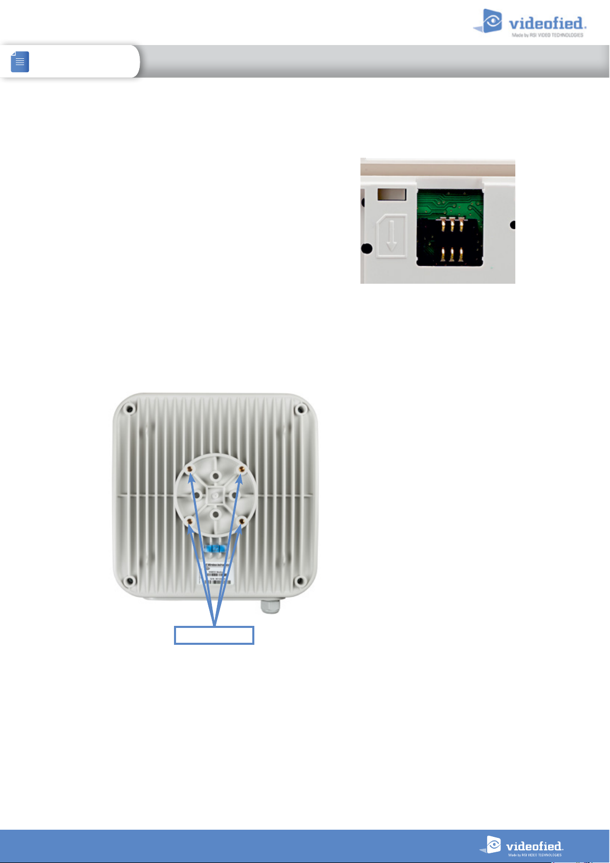
Before removing the front cover from its box, Put the SIM card
on the plastic base (Take care to respect the right direction).
DO NOT insert or remove the SIM card while the panel is
powered.
1.2 Panel bracket mounting
The four screwholes here opposite are intended to
mount the bracket, the latter beeing used to attach the
panel to the wall or a pole.
Mounting the panel is not required for programming.
Screwholes
4
Page 5
INSTALLATION MANUAL
1. PANEL SETUP
XTO / XTO-IP Alarm panel
1.3 Powering and initialization
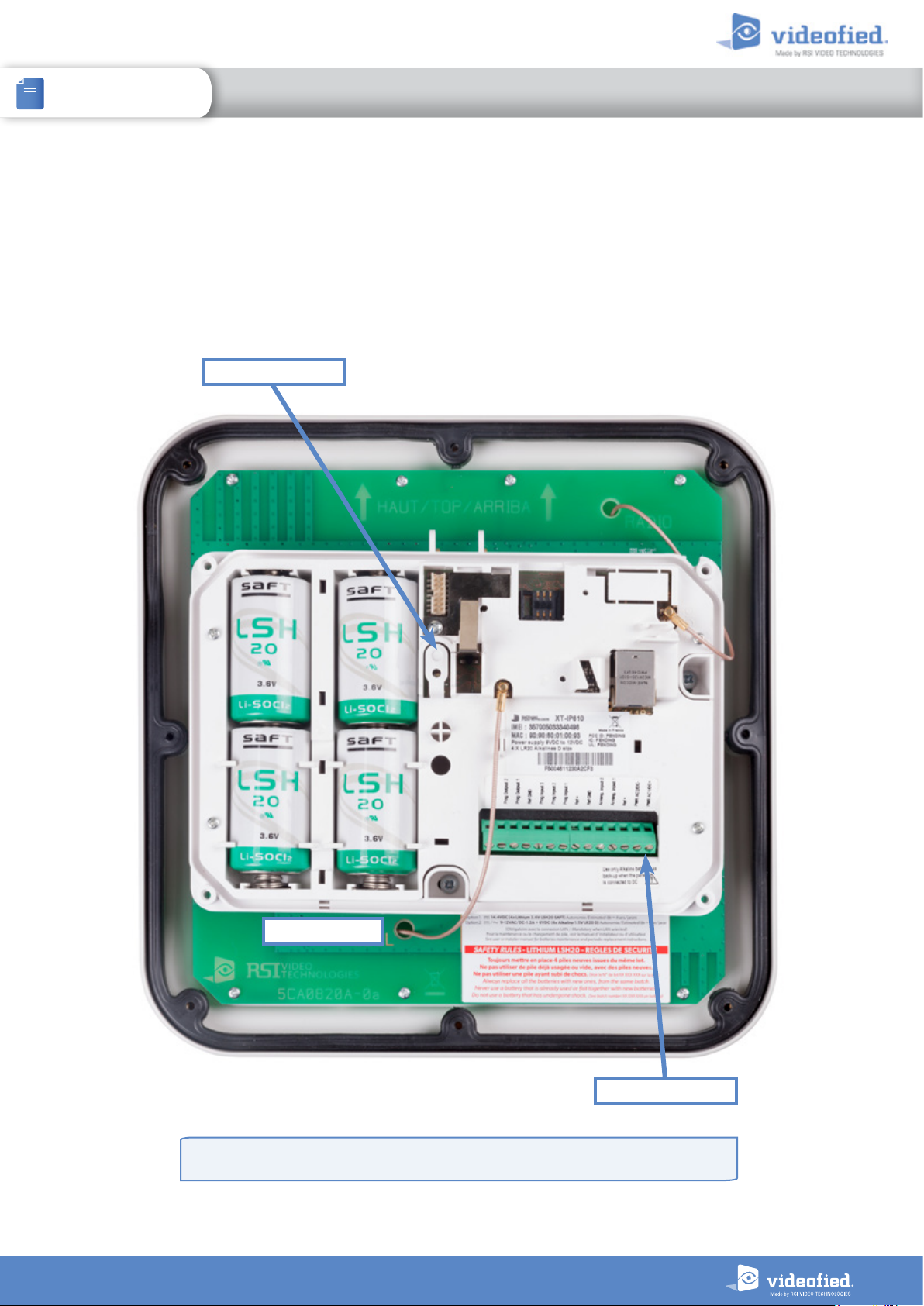
• The panel is powered either with 4 LSH20 Lithium batteries or mains powered with 4 alkaline backup batteries.
• Always replace all 4 batteries at once. Mixing new and used batteries can severely damage the panel (risk of explosion).
• Press and hold the PROGRAMMING BUTTON for 10 seconds, until the indicator LED blinks twice.
• The panel is now reset, a CMA, XMA or XMB has to be enrolled to configure the panel.
Programming button
Lithium batteries
Do not use Lithium batteries when the panel is mains powered
When using Ethernet, only power yor panel with the mains power supply.
Mains Power Supply
5
Page 6
INSTALLATION MANUAL
1. PANEL SETUP
XTO / XTO-IP Alarm panel
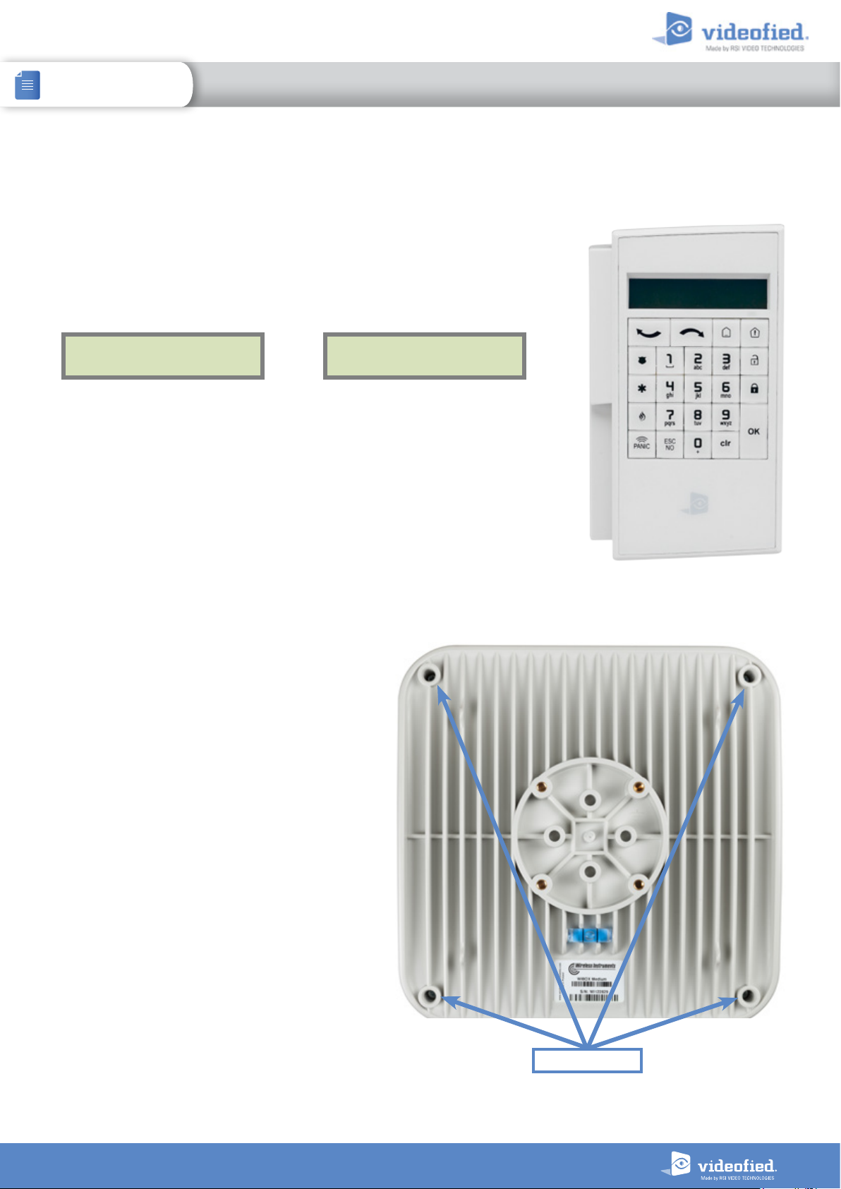
1.4 Pairing the remote keypad
• Press the XTO programming button and release for the enrollment of a programming
keypad.
• Insert all LS14500 Lithium batteries into the keypad.
• Do not mount the keypad. It will display one of the following screens:
RSI (c) 2013
videoed.com
• Press on both
LED on the keypad will blink rapidly. Wait for the keypad to pair.
• If the keypad doesn’t pair up with the panel and shows «XX», it certainly means
that it is still paired to another system and needs to be reset. Take the batteries out,
and press repeatedly on the keypad tamper switch. Then proceed to the above steps.
CLR
and
ESC NO
or
keys at the same time and release. The indicator
<=========XX=========>
1.5 Cover locking
Place and screw the cover on
its support.
Screw locking
6
Page 7
XTO /
XTO-IP Alarm panel
INSTALLATION MANUAL
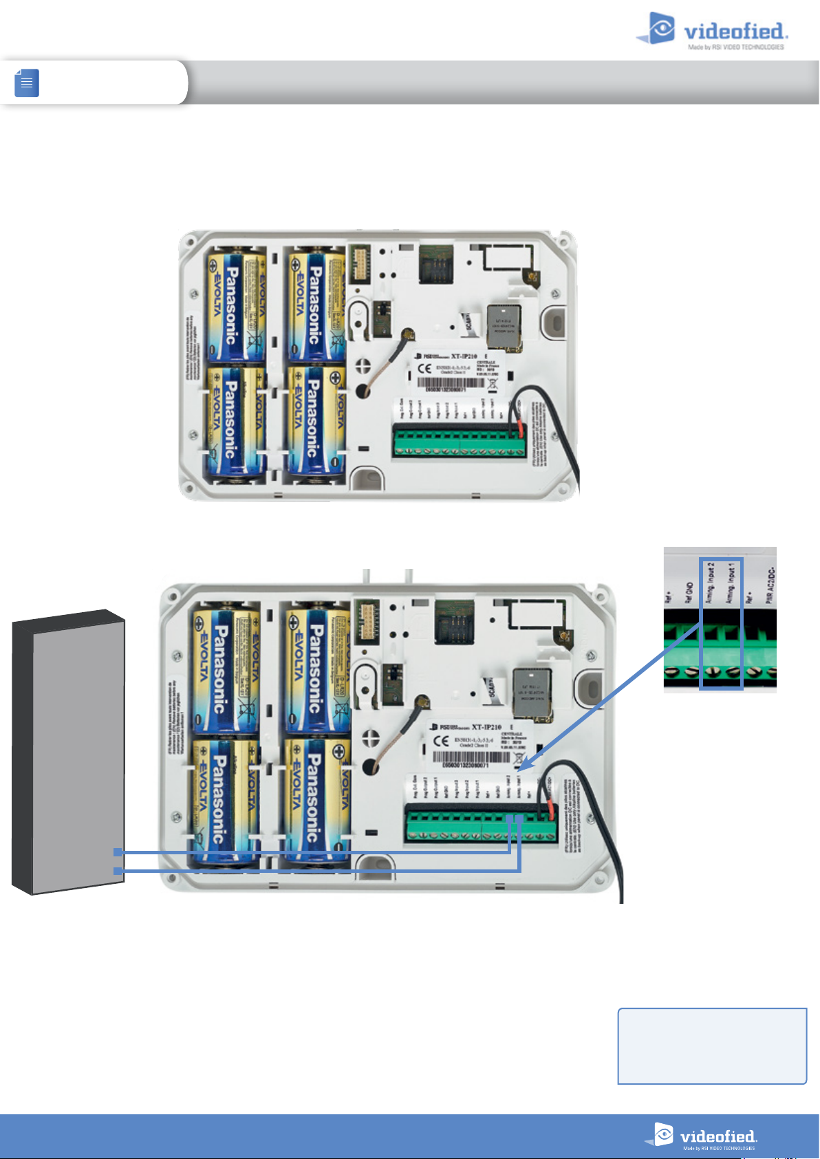
The panel can be used as standard standalone alarm system but it can also be connected to an existing alarm system capable of
latching a 9-12Vcc* voltage used for its arming/disarming.
2. XTENDER MODE
2.1 Standalone Mode
In this functioning mode,
the XTO-iP panel works as a
standard hybrid alarm system
with 25 wireless peripherals
and 3 programmable inputs.
It is a totally standalone alarm
system.
2.2 XTENDER Mode (From the host)
Existing Host
panel
Arming O/P 2
Arming O/P 1
When the panel is used in XTENDER mode, the system will only be able to arm and disarm by latching 9-12Vcc to its arming inputs
Arming Input 1 and/or Arming Input 2.
When the voltage switches to 0V, the panel will disarm automatically.
On a programmed panel, you can choose between standalone and XTENDER modes from the menu :
CONFIGURATION (LVL 4) > GENERAL PARAMETERS > XTENDER
*When using an X TO-iP i n XTENDER
mode, the panel has to be powered
by the mains power supply.
7
Page 8
INSTALLATION MANUAL
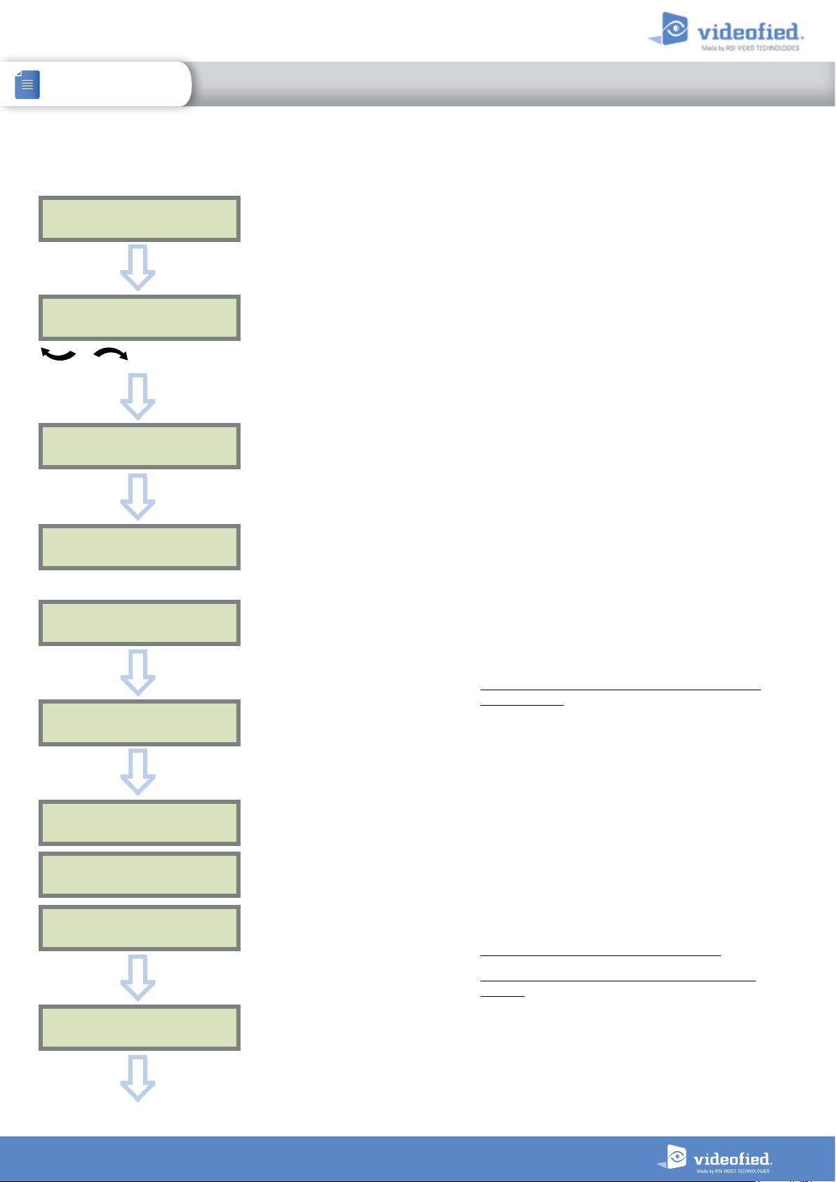
3. XTO-IP PANEL PROGRAMMING
XTO-IP Alarm panel
Keypad Display Actions and comments
KE Y PAD 1
RECORDED
OK or YES
The system can also be programmed in : french, italian,
< - LANGUAGE : - >
ENGLISH (UK)
for language selection
OK or YES
RADIO RANGE TEST?
OK or YES
german, dutch, spanish, swedish, portuguese, danish,
czech and polish.
The language can be changed at any time once the panel
is programmed in the MAINTENANCE menu.
RF TEST
x/9
Please wait
RF TEST
9/9
OK or YES
RADIO RANGE TEST?
ESC
NO
INSTALLER CODE
4 TO 6 DIGITS
THEN OK/YES
INSTALLER CODE :
OK or YES
The Radio Range test must be run during the device
learning process in order to ensure proper pairing with
the control panel. This test measures the strength of
communication between the device and the control
panel. The keypad will display a real time radio range
value on a scale of 9.
To receive the most accurate results you must run the radio
range test for at least 30 seconds.
Result must be 8 out of 9 or better for reliable
transmission.
Using the Alphanumeric Keypad, enter the Installer Code
of your choice.
The Installer Code will be used for all future maintenance
and configuration.
This code is important to keep track of.
There is no back door or Default codes to the
system
CONFIRM CODE
OK or YES
Please refer to the restriction rules for codes (Chapter 4.5).
Some codes are already used by default and therefore
cannot be used.
8
Page 9

INSTALLATION MANUAL
3. XTO-IP PANEL PROGRAMMING
XTO-IP Alarm panel
Keypad display Actions and comments
You may name the installer code using the Alphanumeric
CODE NAME :
Keypad.
If using automatic setting (called installer default list), enter
OK or YES
the name of the list.
Warning : If the wrong installers list name is used it
cannot be set later, the system must be defaulted.
ACCESS 1
REGISTERED
Please wait
Leaving the name blank by pressing
named ‘ACCESS 1’ by default.
ADJUSTING DATE
AND TIME
DAT E ( YE AR):
12/ /
ESC NO
, it will be
To set the year
OK or YES
DATE (MONTH):
13/01/
To set the month
OK or YES
You may proceed in the same way for:
Day, Hour and Minutes.
13/10/14 10:47
ENTRY COMPLETE !
CONNECTED TO
MONITOR. STATION?
OK or YES
ESC
NO
OK or YES
ACCOUNT NUMBER :
ACCOUNT NUMBER :
567001
Use the Alphanumeric Keypad to enter in a 4-8 digit
account number provided by the Central Station.
9
Page 10
INSTALLATION MANUAL
3. XTO-IP PANEL PROGRAMMING
XTO-IP Alarm panel
Keypad display Actions and comments
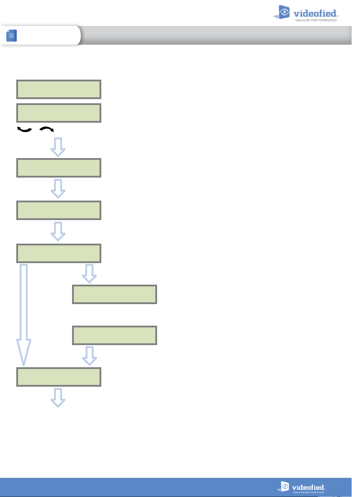
PERIODIC TEST
PERIODIC TEST :
TEST (minutes) :
MODIFICATION?
24 HOURS
To select periodicity
OK or YES
TEST (hour) :
04:
OK or YES
04:15
OK or YES
CODE /STATE
Test Periodicity: 1 hour, 12 hours, 24 hours, 48 hours, 7
days or no tests.
We suggest a 24 hours periodic test call.
ESC
NO
SERVER
ADDRESSES ?
OK or YES
OK or YES
CODE /STATE
MODIFICATION
Wait
ESC
NO
Events list
The CODE/STATE MODIF. menu is to configure the
transmitted events to the monitoring station, use the
arrow keys to toggle between events and
mo dif y.
ALARM: event transmitted upon occurrence.
ALARM/END: event is transmitted on occurrence and on
event restoral.
NOT TRANSMITTED: event is not transmitted, however it
will appear on the keypad.
Please liaise with your Monitoring Station to ensure
that the requested events to transmit are correctly
set.
OK or YES
to
10
Page 11
INSTALLATION MANUAL
3. XTO-IP PANEL PROGRAMMING
XTO-IP Alarm panel
IP1 ADDRESS
0.0.0.0
ESC
NO
SERVER
ADDRESSES ?
ESC
NO
ST R ATEGY:
ETH+2G3G4G
OK or YES
2G3G4G
PARAMETERS ?
OK or YES
DOMAIN NAME 1
PORT 1
888
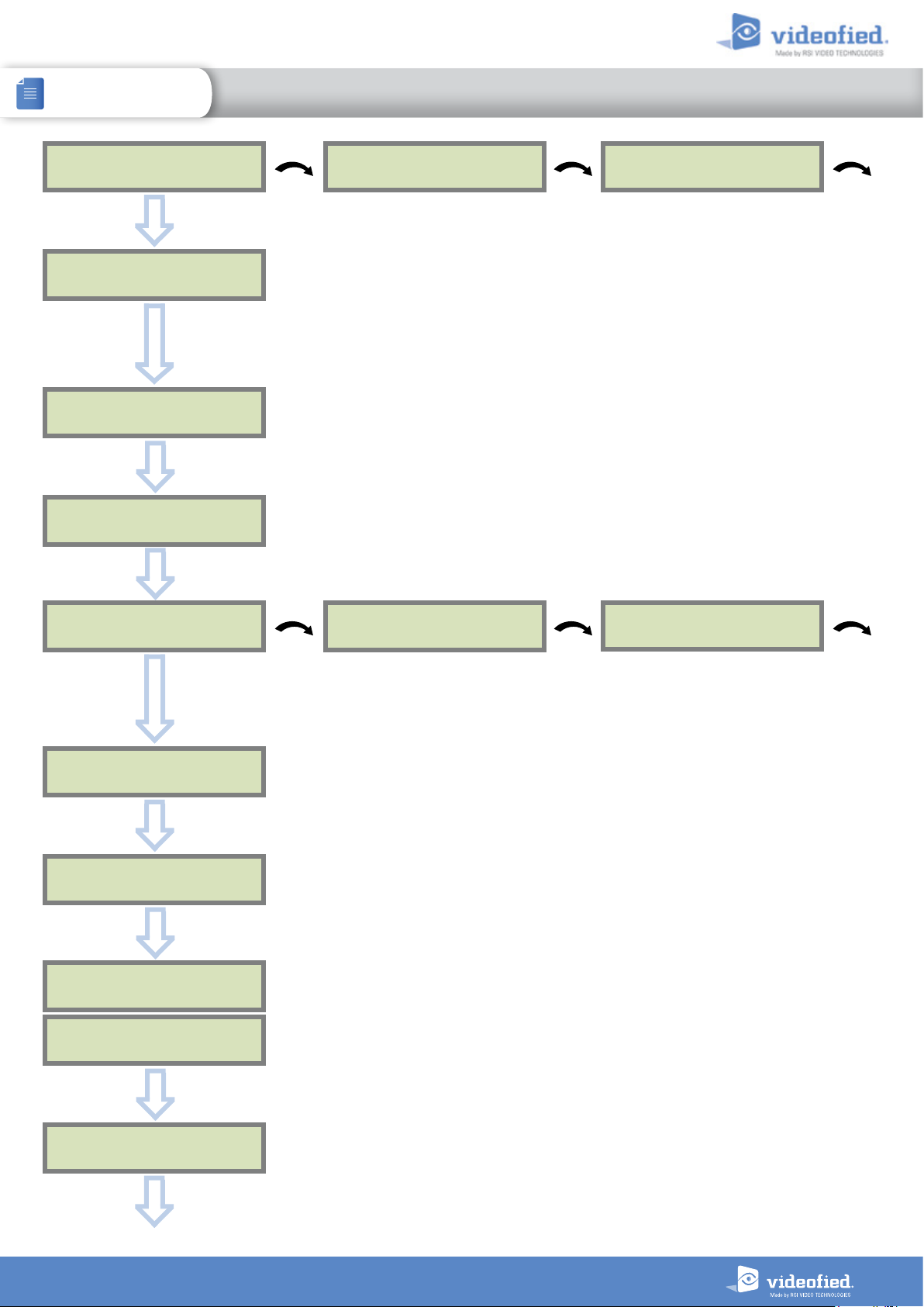
The IP1 address, Domain name 1 and/or Port 1 are provided by the monitoring station.
Leave Port details at 888 unless otherwise instructed.
Press
OK
or
YES
to enter/modify the parameter then OK or
YES
for validation.
WARNING : You will use either an IP address or a Domain name but not both, leave the
Domain name blank if an IP address has already been entered.
Press on the right arrow to configure IP/Domain name 2 and PORT2 (for the back-up server),
and IP/Domain name TMT and PORT TMT (to configure remote maintenance server).
How the alarms and videos are transmitted to the monitoring station ?
ETH+2G3G4G : Ethernet transmission with GPRS backup.
2G3G4G : GPRS transmission only (if the Ethernet connection is not used).
H : Ethernet transmission only (only if GPRS is not used).
ET
Warning : the transmission mode “Ethernet only” is not recommended.
APN CODE
internet-entrepr
ESC
NO
2G3G4G
PARAMETERS ?
ESC
NO
2G3G4G LEVEL ?
OK or YES
TEST IN PROGRESS
END = OK/YES
2G3G4G LEVEL
5/5
OK or YES
USER NAME
orange
The APN Code (Access Point Name), User Name an
PASSWORD
orange
d Password are supplied by the
mobile operator. Please make sure you have entered the code exactly as indicated by your
local SIM card operator.
Press
OK
or
YES
to enter/modify the parameter then OK or
YES
for validation.
Note: When entering your SIM card settings, both APN codes, username and
password fields are case sensitive! It makes a difference between UPPER and lower
case letters.
To switch between UPPER and lower case, use the M/m key from CMA keypad or hold a digit key
(0-9) for XMA/XMB.
Once the 2G3G4G test completed, the keypad will display one of the following results :
- A level between 0/5 and 5/5.
- A GPRS Error code (please see Chapter 7 : 2G3G4G errors codes and contact your
technical support).
If the screens shuts down, press any key to light it up except OK or
YES, ESC NO
or
CLR
.
2G3G4G LEVEL ?
ESC
NO
The 2G3G4G level test can last several minutes. Do not interrupt the test or remove the SIM
card during the test.
IM
PORTANT : Videofied will require a 3/5 grade or better for reliable transmission
of Video alarms.
11
Page 12
INSTALLATION MANUAL
3. XTO-IP PANEL PROGRAMMING
XTO-IP Alarm panel
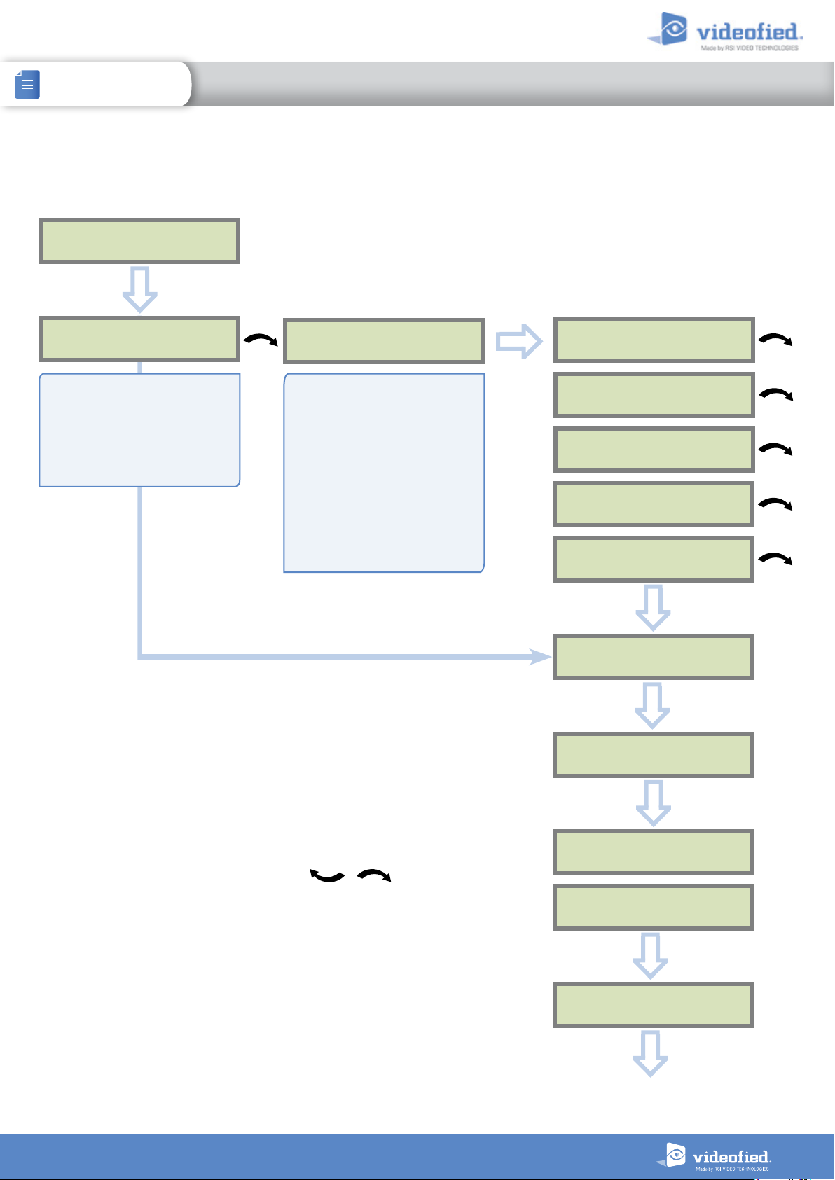
ETHERNET parameters configuration
IP
PARAMETERS ?
OK or YES
DHCP :
ENABLED
By setting the DHCP as ENAB LED,
a new IP address will be assigned
dynamically to the panel every
time it connects to the network.
Network parameters will not be
asked.
OK or YES
DHCP :
DISABLED
If the router forces a static IP
address for the panel, there will
then be a need to define DHCP
as DISABLED. You will then need
to fill in the following network
parameters fields : Panel IP, IP
Mask, Primary DNS, Gateway
and Secondary DNS.
Warning: Verify that the IP
address selected is available on
the Network and accepted by the
router.
OK or YES
PANEL IP
IP MASK
PRIMARY
DNS
GATEWAY
SECONDARY
DNS
ESC
NO
IP
PARAMETERS ?
ESC
NO
During this test, the panel tries to connect to the
local Ethernet Network. The result of this test
can be:
• If the connection is successful: the local IP
of the panel will be displayed (you can
display other Ethernet parameters with the
arrows ).
• ETHERNET OFF NO STATUS : the
Ethernet module is switched off. Please
verify that the Ethernet cable is connected
and try again.
• NETWORK/CABLE MISSING : the panel
doesn’t detect Ethernet Cable or Network.
ETH. STATUS?
OK or YES
TEST IN PROGRESS
END = OK/YES
PANEL IP
XXX.XXX.XXX.XXX
ESC
NO
ETH. STATUS?
ESC
NO
12
Page 13
INSTALLATION MANUAL
3. XTO-IP PANEL PROGRAMMING
XTO-IP Alarm panel
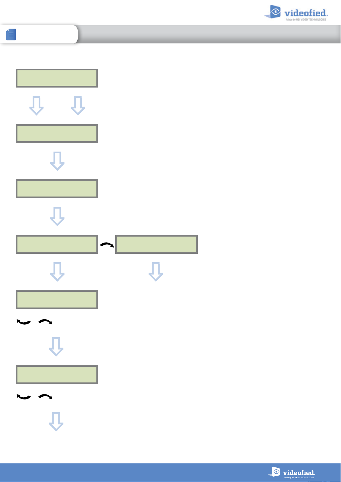
COMPATIBILITY
EN 50131 NORMS ?
OK or YES
ESC
NO
AREAS CONFIGURATION
OK or YES
AREA 1 NAME :
OK or YES
ARMING PROFILE :
STANDALONE
ARMING PROFILE :
FROM THE HOST
For full compatibility with EN50131, press OK or
Otherwise, press
Press
ESC NO
Enter the name of the area 1 and
ESC NO.
to default the area names.
OK
or
YES
YES
.
.
Repeat the procedure for areas 2,3 and 4.
For further details, please refer to chapter 4.3.
Your choice will depend on how you are arming the
system :
Standalone : Will make the XTO-iP a completely
independant system controlled by arming
and disarming using Videofied peripheral
devices(keyfobs, keypads, badge,readers).
From the host : Will make the XTO-iP panel a
piggyback/xtender system that will only arm and
disarm off the latching of 9-12V on the arming
inputs 1 & 2.
OK or YES
EXIT DELAY :
45 sec
For the selection
OK or YES
ENTRY DELAY :
15 sec
For the selection
Please go to page 15 if you chose
STANDALONE
Please go to page 14 if you chose
FROM THE HOST
Other values are available: 2 min, 1 min, 45 sec.
Other values are available: 2 minutes, 1 minutes, 45
seconds,30 seconds or 15 seconds.
13
Page 14
INSTALLATION MANUAL
3. XTO-IP PANEL PROGRAMMING
XTO-IP Alarm panel
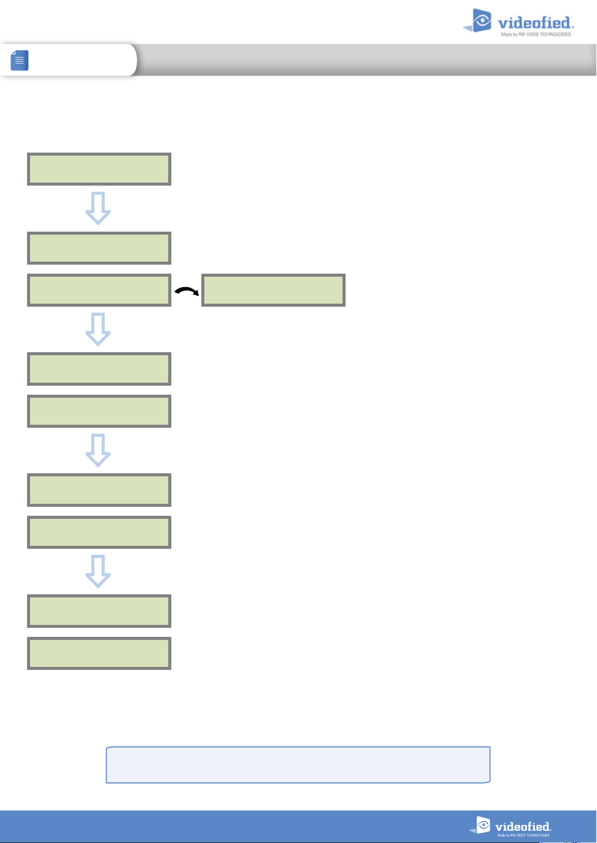
XTENDER mode configuration
ARMING PROFILE :
FROM THE HOST
OK or YES
ARMING MODE
MODE :
SLOW
OK or YES
MODE SLOW : The panel will arm each device one at
a time saving battery life. We recommend this mode.
MODE FAST : The panel will arm all devices at the
MODE :
FAST
same time. This mode increases significantly the
battery consumption.
OK
or
YES
to choose the parameter.
ENTRY DELAY
VALUE (0-255) :
(000) : _
OK or YES
TRANSMISSION DELAY
VALUE (0-600) :
(000) : _
OK or YES
ARMING CONFIRMATION
VALUE (0-240) :
(0) : _
Enter the value for your Entry Delay up to 255 seconds
OK
or
and press
Note : In From the Host mode, the entry/exit delay are
dealt by the master system.
The transmission delay value sets the delay between
the detection of an event and its transmission to the
monitoring center.
Except when specifically required, please enter 0.
Enter the value you would like for the Transmission
Delay and press
Arming Confirmation is the number of seconds the
system will wait to arm after voltage is latched on
the arming input. This feature can be used as an exit
delay, we suggest you to enter the same value as
your master system exit delay.
Enter the value you would like for the Arming
Confirmation and press
YES.
OK
or
YES.
OK or YES.
For further information about the programmable inputs and outputs, please consult the following
application notes available on our support website:
240-XT - APP NOTE - XTENDER CONFIGURATION MODE
14
Page 15
INSTALLATION MANUAL
3. XTO-IP PANEL PROGRAMMING
XTO-IP Alarm panel
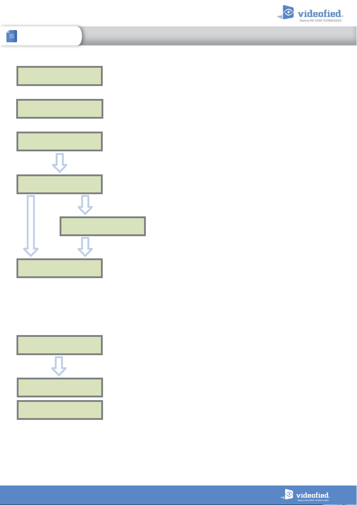
RECORDING
DEVICES
PRESS PROGRAM
BUTTON OF DEVICE
ENTERING A NEW DEVICE ?
ESC
NO
BADGE ENTERED ?
OK or YES
ESC
NO
END OF
CONFIGURATION
RECORDING A
NEW BADGE ?
ESC
NO
Each device has a unique programming button or a
specific manipulation. Please refer to the Installation
Sheet for the device you would like to program.
Please check the radio level of each device on its final
location. The result must be 8 out of 9 as a minimum
(Please refer to the Radio Range section, page 8 for
further details).
Each system can embrace a maximum of 25 devices,
programming keypad included.
Press
OK or YES
move to the next step.
Aer initial programming has been completed, the system
cannot be armed or disarmed until a user code or badge
is entered (the installer code cannot arm or disarm the
system).
Press
OK or YES
ESC NO
If you wish to use an user code, please skip this step
and when initial programming is completed go to the
BADGES/ACCESS CODES menu (please refer to chapter
4.4 for further details).
Badges and codes are limited to 19 for user (level 2 or 3) +
1 installer code.
if you’re not using any badges.
to enter a new device or
to register one or more badges.
ESC NO
to
OPERATION
COMPLETED ?
OK or YES
SYSTEM CHECK
IN PROGRESS
INSTALLATION SUCCESSFUL !
Before completing programming make sure that no device
is tampered. Each device must be closed and its LED
indicator shall be turned off.
Aer initial programming has been completed, make
use of the menu overview document (available on our
technical support website), to see full programming
options.
15
Page 16
INSTALLATION MANUAL
4. FEA
TURES GUIDE
XTO-IP Alarm panel
4.1 Get to Access level 4
Tue 29/10 11:23
DISARMED LVL:1
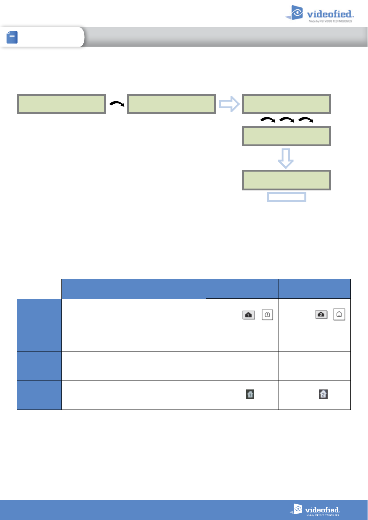
To unlock and get access to the installer level 4, you need to successively enter TWO codes
(in any order) :
• INSTALLER CODE (entered during intial programming).
• USER CODE (Level3): the user must authorize the installer to get access to the
configuration of his panel.
ACCESS LEVEL
1
OK or YES
4.2 How to Arm/Disarm the System
When in standby mode, the system can be armed with the remote keypad, the remote keyfob
and/or the remote badge reader.
ACCESS LEVEL
LEVEL : 1
ACCESS LEVEL
LEVEL : 4
OK or YES
BADGE OR CODE
OK or YES
With remote
keypad
With remote
badge reader
BR250
With remote
keyfob
Full arming with
user code
Enter your user code
and press
OK or YES
N/A
N/A N/A
Full arming with badge Special Arming 1 Special Arming 2
Present your badge on
the keypad
( XMB model only)
Present your badge on
the badge reader
Press /
enter your user code
and press
Press Press
OK or YES
N/A N/A
Press /
press
OK or YES
your user code
and enter
16
Page 17
INSTALLATION MANUAL
4. FEA
TURES GUIDE
XTO-IP Alarm panel
4.3 Arming and Siren Mode Configuration
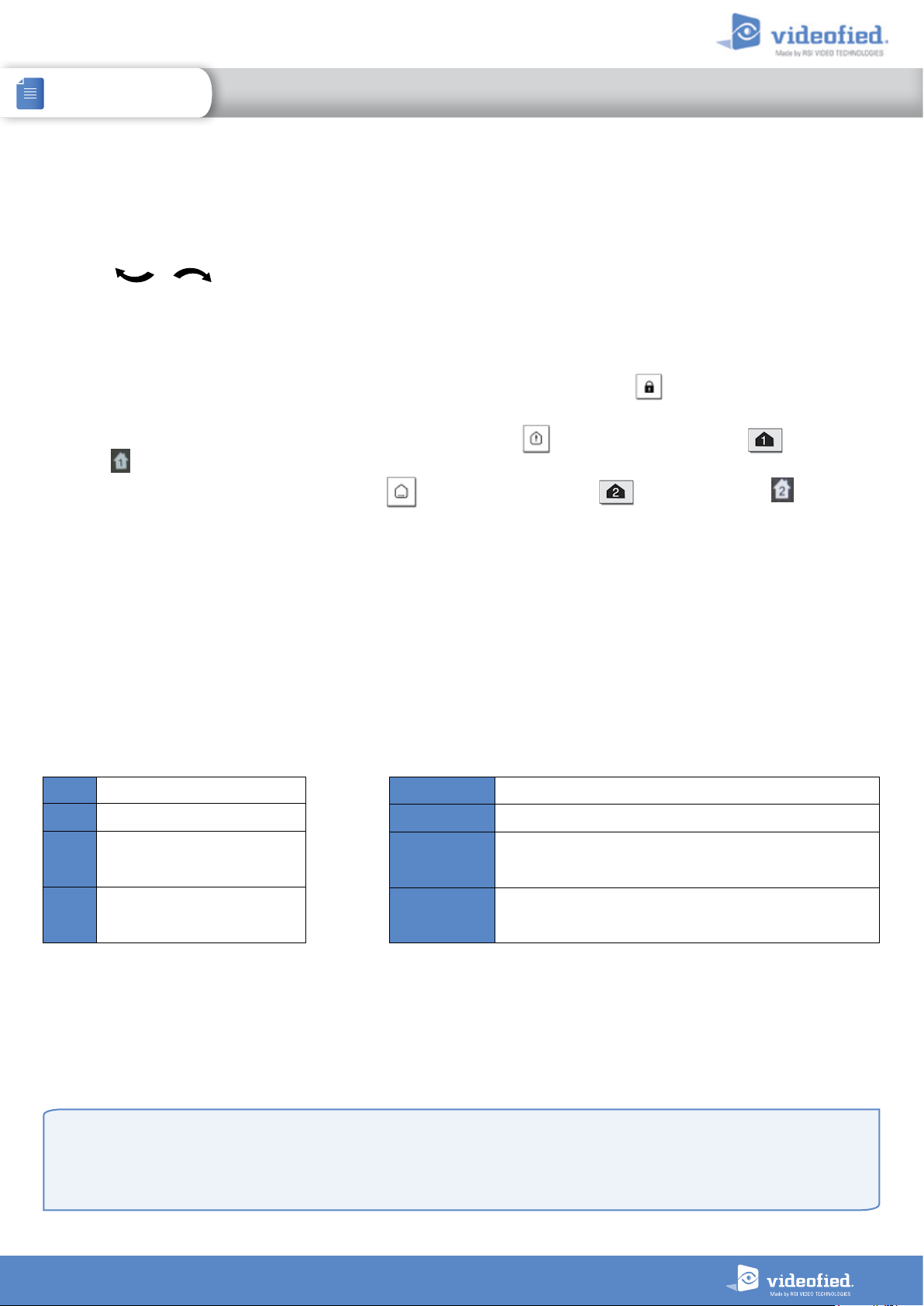
• Use the to go to menu :
CONFIGURATION (LEVEL 4) > SPECIAL ARMING MODES > FULL ARM, SP1 or SP2 use direction arrows to select the arming mode you
want to modify and
OK / YES
.
• There are 3 different arming modes :
FULL ARM : Arming of all areas and all devices. Use a badge or a user code and press
YES
key on the CMA keypad.
SP1 : Partial Arming (1) is enabled by entering the user code and pressing on the XMA/XMB keypad, the key on the CMA
keypad or on the remote keyfob RC.
SP2 : Partial Arming (2) is enabled by pressing the key on a XMA/XMB keypad, on a CMA keypad, or on the remote
keyfob RC.
For each arming mode, it is possible to specify how each of the 4 areas will be armed and how the system will behave during an alarm.
Areas : 1 2 3 4 Each time you press the corresponding number, the system will toggle the arming
State : A A A A Press
A Armed
D Disarmed
state for the respective area.
OK / YES
will be in effect for this special profile. Select the siren mode using the direction arrows then
press
OK / YES
aer this configuration step. The system will then display what siren mode
.
Siren Immediate triggering of all sirens
Delay Beeps Entry/Exit delay beeps, then triggering of all sirens
OK
/ on the XMA/XMB keypad or the
P
(by default : all opening contacts*)
E
* You can set your dev ices as : Extern al, Perimeter, ou Extern al +Perimeter. Please go to the menu:
CONFI GURATION (LVL 4) -> AREAS AN D DEVICES -> DEV ICES -> DEVICE S CONFIGUR ATION -> DE VICE TYPE
When in the ‘Arm From Host’ mode, the Videofied system will only arm and disarm when 9-12v is supplied and sustained.
When both arming inputs are supplied voltage at the same time the Videofied Keypad display will show ‘SYSTEM ARMED.
When only one arming input is supplied voltage the Videofied Keypad display will show ‘PART LVL #’
• Arming Input 1 will arm/disarm Areas 1 & 2 – Area 1 is delayed by default
• Arming Input 2 will arm/disarm Areas 3 & 4– Area 3 is delayed by default
(by default : all opening contact s
Perimeter
External
with external access*)
Silent No Sirens, No Beeps
Without Siren Beeps on the keypad only
17
Page 18
INSTALLATION MANUAL
4. FEA
TURES GUIDE
XTO-IP Alarm panel
4.4 Manage badges and access codes
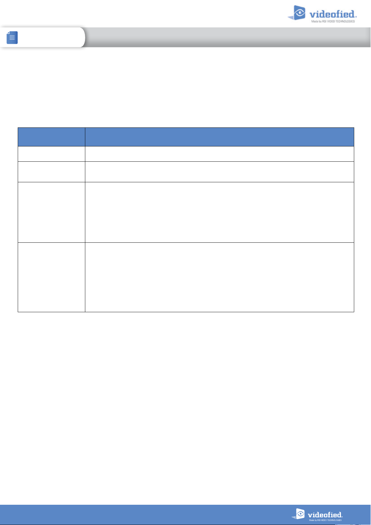
Access Level
Access Level Definition & Rights
LVL 1 Standby Level
LVL 2
LVL 3
LVL 4
Codes and badges get rights access to one of the 4 available levels of access.
Restricted USER level, where it is only possible to arm/disarm the system.
USER level, where it is possible to arm/disarm the system, check the event log, test the devices.
Modifications of the settings are not possible at this level.
User Level 3 can create Level 2 or Level 3 access codes or badges.
INSTALLER level, where it is possible to modify the setup of the panel. .
To access Level 4, the approval of a Level 3 oe Level 2 user is required.
Installer Level 4 can create the first Level 3 access code only.
How to return to the LVL1?
• Aer 1 min of no use of the keypad and no tests running, the display returns to the standby display and LVL1.
• When standby display, if the
ESC NO
key is held during 5s, the level is changed to LVL1.
18
Page 19
INSTALLATION MANUAL
4. FEA
TURES GUIDE
XTO-IP Alarm panel
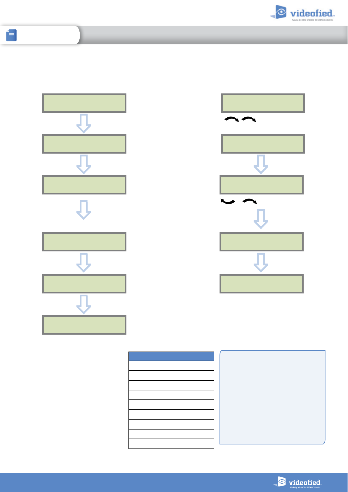
Enter a new end user Badge/Code Delete an end user Badge/Code
BADGES
ACCESS CODES
OK or YES
ENTER A
BADGE/CODE
OK or YES OK or YES
BADGE OR CODE
Enter a 4-6 digit user code and
OK or YES
or present a badge in front of the reader until
you hear the registration beep.
CONFIRM THE
CODE
OK or YES
ENTER A
BADGE/CODE
Press twice on the right
arrow
DELETING
BADGES/CODES
Badges/codes list
Select badge/code
then
OK or YES
DELETING CODE
ACCESS 5
OK or YES
CODE NAME :
OK or YES
ACCESS 2
ENTRY COMPLETE
Reserved Codes
Up to 19 codes (or badges) can be registered
into the panel with the engineer code.
A code has 4 to 6 digits (0 to 9).
The table presents the reserved code
possibilities that cannot be used.
Those codes are used for maintenance or as
panic/duress codes.
A total of 186 codes are forbidden.
Reserved Codes
000000
From 9998 to 9999
From 99998 to 99999
From 999898 to 999999
From 314157 to 314159
All user codes +1
All user codes +2
All user codes -1
All user codes -2
CODE
DELETED
When a code is created (1000 for example),
the 2 next codes and previous codes (0998,
0999, 1001 and 1002) will be automatically
reserved.
The +1 code (1001) is used for disarming
under duress.
The +2 code (1002) is used for panic.
The -1 and -2 codes (0998 et 0999) are
reserved to prevent conflicts when creating a
new user code.
19
Page 20
INSTALLATION MANUAL
4. FEA
TURES GUIDE
XTO-IP Alarm panel
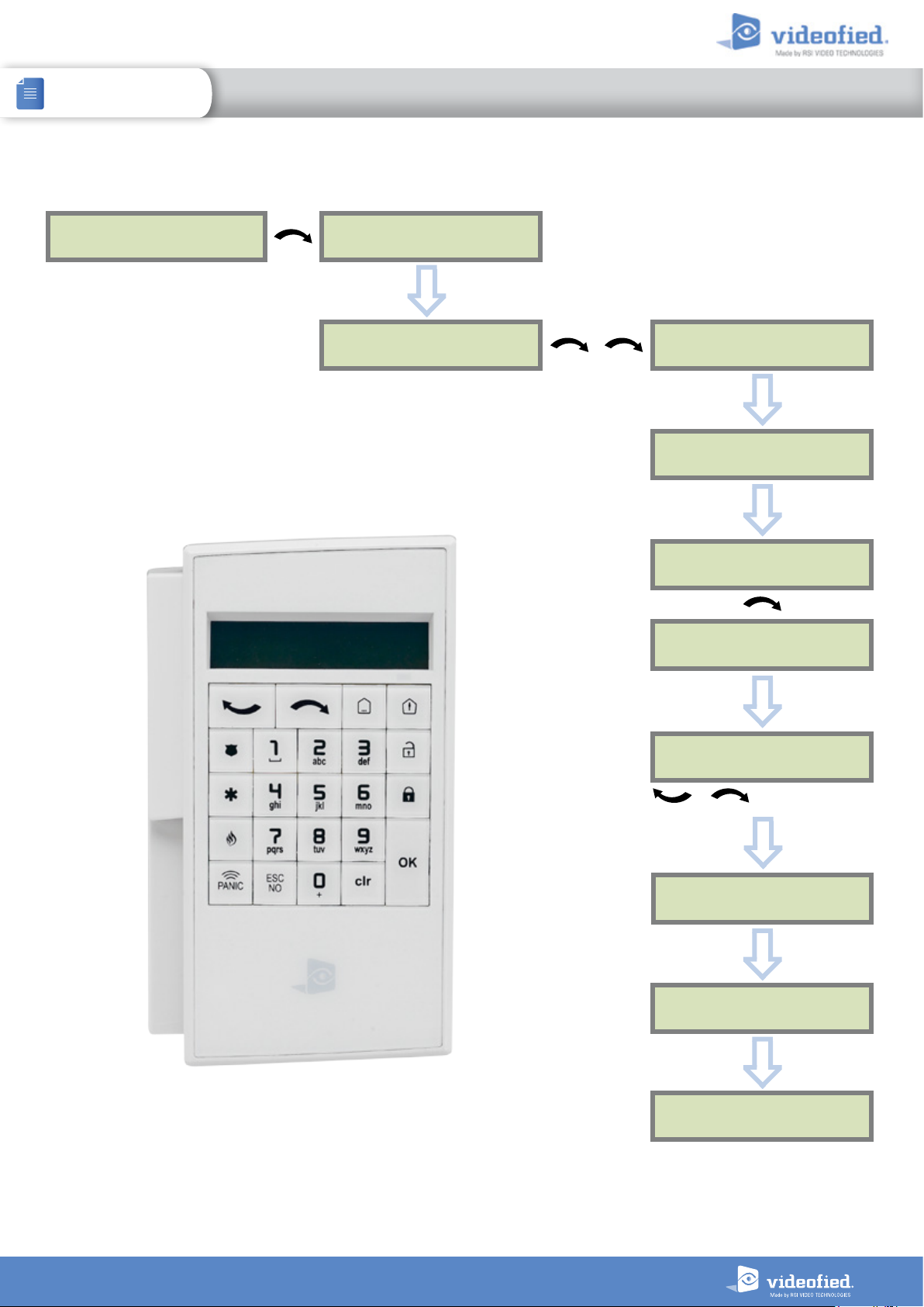
4.5 Delete the keypad or any other device
ACCESS LEVEL
4
CONFIGURATION
OK or YES
GENERAL
PARAMETERS
AREAS AND
DEVICES
OK or YES
DEVICES
OK or YES
ADD A NEW
DEVICE
DEVICE
CONFIGURATION
OK or YES
Devices list
to select the device
and press
OK or YES
A1 : KEYPAD
KE Y PAD 1
OK or YES
DELETE
OK or YES
< = = = = XX = = = = >
You can now remove the batteries from
the device
20
Page 21
INSTALLATION MANUAL
4. FEA
TURES GUIDE
XTO-IP Alarm panel
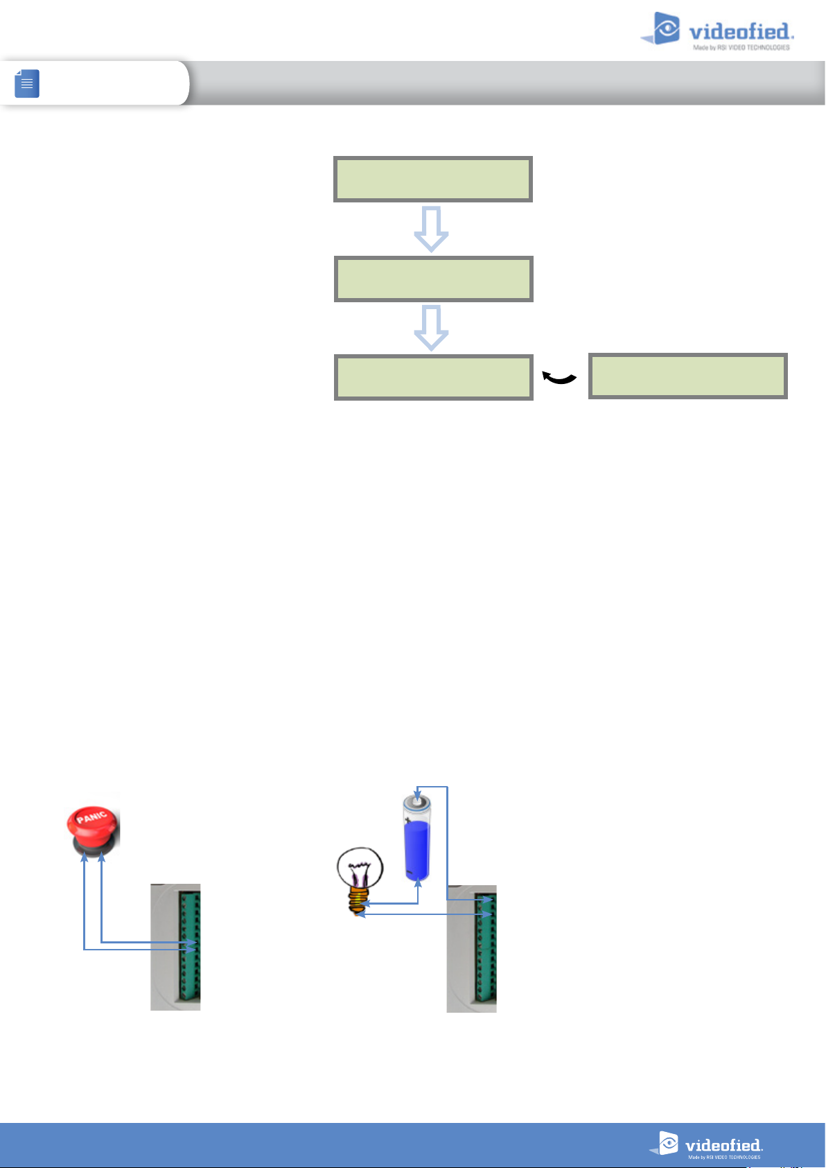
4.6 Read the event log
EVENT
LOG
When user disarms the system, the keypad
indicates the last event.
In case of the user needs to read the full log
file, use the keypad to go in EVENT LOG,
OK
or
YES
press
on SELECT LAST EVENTS
and use arrow to list the events.
15/10/13 11:29
OK or YES
SELECT LAST
EVENTS
OK or YES
MO DIFIED PAR A M ET
Press OK or
15/10/13 11:10
YES
for more info rmation about an event
SYSTEM DISARMED
4.7 Programmable inputs and outputs
The XTO-iP control panel has 3 programmable inputs and 2 programmable outputs. Please note that we advise to connect the panels
to a power supply when using programmable inputs. These functions allow the linking of Videofied® security systems to auxiliary
equipment such as panic buttons, pepper spray, smoke generator, hard-wired door contact, light curtain, etc.
PROGRAMMABLE INPUT 1, PROGRAMMABLE INPUT 2 and PROGRAMMABLE INPUT 3 are triggered by voltage between 9V
and 15V and an current between 1,5mA (@9V) and 3mA (@15V). If a dry contact is used to trigger the programmable inputs, the
REF+output can be used to supply this dry contact.
PROGRAMMABLE OUTPUT 1 and PROGRAMMABLE OUTPUT 2 can be triggered either by a panel event, by a peripheral device or
by an external event such as a programmable input or a arming input.
The XTO-iP control panel also offer a mapping feature. Mapping option allows the input to generate a video-clip via a MotionViewer
when a programmable input is triggered and/or when an event occurs.
Prog. Out . COM
Prog. Output2
Prog. Output1
Ref GND
Prog. Input3
Prog. Input2
Prog. Input1
Ref+
Ref GND
Arming Input2
Arming Input1
Ref+
PWR AC2/DCPWR AC1/DC+
Prog. Out . COM
Prog. Output2
Prog. Output1
Ref GND
Prog. Input3
Prog. Input2
Prog. Input1
Ref+
Ref GND
Arming Input2
Arming Input1
Ref+
PWR AC2/DCPWR AC1/DC+
For further information about the programmable inputs and outputs, please consult the following application notes available on our support website:
240-XV-XT - PROG INPUTS - APP NOTE
240-XV-XT - PROG OUTPUTS - APP NOTE
21
Page 22
INSTALLATION MANUAL
4. FEA
TURES GUIDE
XTO-IP Alarm panel
4.8 Golden rules
1
Area 1 is always delayed.When you register a keypad or a badge
reader into an area, that area will automatically be delayed.
2
Never position a panel next to a high voltage electrical cabinet .
3
Press CLR to erase a typing mistake.
4
Never register the same device twice (delete from the system first).
5
Registration of up to 25 devices (including the keypad).
6
Respect indoor infrared devices installation height (2m10 to 2m30).
7
Outdoor cameras have to be installed at 2m60 to 3 meters
height. Those devices needs to to protect an access and not a zone.
8
Do not fix the keypad at the beginning of the installation as it will
need to be portable during programming.
9
Always clean the lens of the cameras aer the installation
(Use a clean, dry cloth, taking care not to exert pressure on
the lens).
10
To switch between UPPER and lower case, use the M/m
key from the CMA keypad or hold a digit key (0 to 9) for
XMA/XMB.
11
Internal components are fragile, be careful opening or
closing the panel.
12
LCD screen goes dark aer 30 seconds of inactivity, press an
arrow or numeric key to light it up.
13
Use only batteries provided by Videofied (siren : Alkaline
batteries).
14
Infrared detectors should never be installed in stairs or close
to stairs (false alarm risks).
15
A colon display [:] means that the parameter can be
changed.
22
Page 23
XTO /
XTO-IP Alarm panel
INSTALLATION MANUAL
5. TRANSMITTED EVENTS LIST
The XTO-iP pane l can be configured to enable or disabl e the transmission
of events like alarms or defaults.
The installer can modify the default sending settings for those events,
although it will end the EN50131 standard compliance.
These are the default transmitted events :
DEVICE (intrusions)
ALERT (Panic Buttons)
PANEL LOW BATT.
TAMPER
DEVICE LOW BATT.
PERIODIC TEST
DURESS CODE
FIRE
MEDICAL ASSIST.
ETHERNET CABLE
AC POWER LOSS (AC Power supply)
ALARM : event transmitted upon occurrence
ALARM/END : event is transmitted on occurrence and on event restoral
NOT TRANSMITTED : event is not transmitted, however it will appear on the keypad.
Example :
If the monitoring station system is set to receive arms and disarms, the ARM / DISARM parameter must be
changed from NOT TRANSMITTED to ALARM / END.
The following events are not sent by default :
PANEL RESET
PHONELINE FAULT
RADIO JAMMING
SUPERVISION
5 WRONG CODES
ALARM CANCEL
ARM/DISARM (On/Off)
ZONE BYPASS (bypass function enabling/dsiabling)
SWINGER SHUTDOWN
There are 3 different transmission states :
How to modify the transmission state
• At initial programming, right aer the PERIODIC TEST CALL step:
CODE /STATE
MODIFICATION
Press
OK or YES
to access EVENT TRANS. MODIFICATION menu.
• Aer initial programming, using a remote keypad :
Use the arrows to access :
CONFIGURATION (level 4) > CONFIGURATION MONITOR. STATION > MONITORING PARAMETERS > EVENT TRANS. MODIFICATION
Then use the arrows to determine the event to modify. Press
OK or YES
to edit.
23
Page 24
XTO /
XTO-IP Alarm panel
INSTALLATION MANUAL
6. 2G3G4G ERROR CODES
IMPORTANT: The PIN of the SIM card has to be deactivated or 00000.
The following is a list of error codes that can appear after the 2G3G4G test.
2G3G4G
LEVEL :
ERROR XXX
Codes Errors
03 ou 04LP
003
010
011
012
013
014
015
No network coverage or no SIM card
inserted
SIM card not detected/not inserted
SIM not inserted
PIN code necessary
-> PIN code must be deactivated
PUK code necessary, SIM card blocked
Default SIM card
SIM card busy
Error on SIM
In case of 2G3G4G (GPRS) errors during initial programming, we strongly
suggest to continue with the installation and perform the 2G3G4G (GPRS)
level test again once achieved.
This error checklist is provided for information purposes only.
This is not a comprehensive list, but it is representative of most
cases. Some events or codes are subject to change by SIM card
operators.
However, the GPRS level test errors results in the majority of cases
have the following causes :
• SIM Card activation Delay:
Some operators require an additional delay up to 48 hours to
activate automatic data transmission. Please check with your operator
prior to installation.
• APN CODE, USERNAME and PASSWORD :
The GPRS (2G3G4G) settings are supplied by the operator. Please
make sure you have entered the code exactly as indicated by your
local SIM card operator.
030, 043,
057, 102,
132, ...
• No network coverage
• Typographical error in the APN Code,
username, password
• SIM card not activated
Note: When entering your SIM card settings, both APN codes,
username and password fields are case sensitive! (It makes a
diffe
rence be
To switch between UPPER and lower case, use the M/m key from CMA
keypad or hold a digit key (0-9) for XMA/XMB.
• Insufficient GPRS Network:
When the panel is unable to find any signal, proceed to GPRS level
test in another location on site. You can also find the network state or
condition of use by directly contacting your local operator.
tween UPPER and lower case letters).
24
Page 25

XTO /
XTO-IP Alarm panel
INSTALLATION MANUAL
7. TECHNICAL SPECIFICATIONS AND SECURITY NOTES
FCC Regulatory Information for USA and CANADA
FCC Part 15.21 Changes or modifications made to this equipment not expressly approved by RSI Video Technologies may void the FCC
authorization to operate this equipment.
FCC Part 15.105 Class B
This equipment has been tested and found to comply with the limits for a Class B digital device, pursuant to Part 15 of the FCC Rules. These
limits are designed to provide reasonable protection against harmful interference in a residential installation. This equipment generates, uses
and can radiate radio frequency energy and, if not installed and used in accordance with the instructions, may cause harmful interference
to radio communications. However, there is no guarantee that interference will not occur in a particular installation. If this equipment does
cause harmful interference to radio or television reception, which can be determined by turning the equipment off and on, the user is
encouraged to try to correct the interference by one or more of the following measures:
Reorient or relocate the receiving antenna.
>
Increase the separation between the equipment and receiver.
>
Connect the equipment into an outlet on a circuit different from that to which the receiver is connected.
>
Consult the dealer or an experienced radio/TV technician for help.
>
Radio frequency radiation exposure information according 2.1091 / 2.1093 / OET bulletin 65
This equipment complies with FCC radiation exposure limits set forth for an uncontrolled environment. This equipment should be installed and
operated with minimum distance of 20 cm between the radiator and your body.
Cet équipement est conforme aux limites d’exposition aux rayonnements IC établies pour un environnement non contrôlé.
Cet équipement doit être installé et utilisé avec un minimum de 20 cm de distance entre la source de rayonnement et votre corps.
This transmitter must not be co-located or operating in conjunction with any other antenna or transmitter.
This device complies with Part 15 of the FCC Rules and with RSS-210 of Industry Canada.
Operation is subject to the following two conditions:
1 This device may not cause harmful interference, and
2 This device must accept any interference received, including interference that may cause undesired operation.
Le présent appareil est conforme aux CNR d’Industrie Canada applicables aux appareils radio exempts de licence.
L’exploitation est autorisée aux deux conditions suivantes:
1 L’appareil ne doit pas produire de brouillage, et
2 L’utilisateur de l’appareil doit accepter tout brouillage radioélectrique subi, même si le brouillage est susceptible d’en compromettre
le fonctionnement.
Security notes / (FR) Notes de sécurité / (DE) Hinweise zur Sicherheit
• Remove battery before any
English
maintenance !
• WARNING, there is a risk of explosion
if a battery is replaced by an incorrect
type!
• Observe polarity when setting up the
batteries!
• Do not throw used batteries!
Bring them to your installer or a
collection point.
• Retirez les piles avant toute opération
Français
de maintenance !
• Attention ! Il y a un risque d'explosion si
l'une des piles utilisées est remplacée
par une pile de type incorrect !
• Respectez la polarité lors de la mise en
place des piles !
• Ne jetez pas les piles usagées !
Ramenez-les à votre installateur ou à un
point de collecte spécialisé.
• Batterien vor jeglichen Wartungsarbeiten
entfernen!
• Vorsicht, es besteht Explosionsgefahr,
wenn eine Batterie durch eine Batterie
falschen Typs ersetzt wird!
• Achten Sie beim Einsetzen der Batterien
auf die Polung!
• Entsorgen Sie Batterien nicht im normalen
Haushaltsmüll! Bringen Sie Ihre verbrauchten
Batterien zu den öffentlichen Sammelstellen.
Deutsch
25
Page 26
XTO /
XTO-IP Alarm panel
INSTALLATION MANUAL
7. TECHNICAL SPECIFICATIONS AND SECURITY NOTES
ELECTRICAL DATA
Power requirements (option 1)
Power supply Type B 9-12 V / 1.2 A
Low voltage limit 5.15 V
Backup 6V with 4 x 1,5 V D Alkaline batteries /LR20
Low battery limit 4.2 V
Battery life (average) 1 year
Average current
consumption (over 1h)
Max current 1.2 A
Power requirements (option 2, not available for Ethernet)
Power supply type C
Low battery level
Average battery life
RF Wiselink® technology
Radio type
Operating frequency
868MHz - XTO-iP210 (Europe, South Africa, Asia)
865-867MHz - XTO-iP310 (India)
902/928MHz - FHSS – XTO640 (USA, Canada, South America)
915/928MHz - FHSS – XTO-iP 730 (Australia, South America)
902/907.5MHz & 915/928MHz – FHSS – XTO-iP 830 (Brazil)
Transmission security
Radio jam detection
Supervision
Radio antenna
External radio antenna
Tamper Detection
Tamper
14.4V with 4 x 3.6 V Lithium batteries /LSH20
AES encryption algorithm
Option with MMCX connector
Wall and cover tamper detection
450µA
4 years
Bidirectional RF
Integrated
BOX
Physical and Environmental Data
Operating temperature
Maximum relative humidity
International Protection Marking
Material
Installation / Mounting
Control panel / Base
95%, without condensing
4 screws to close the cover
4 screws on panel base for brackets mounting
-25°/70°C
IP54 / IK06
ABS—ULV0
12 V
Yes
Yes
TRANSMISSION
Communicator
Communicator type
2G frequencies
800/850(B5), AWS1700(B4), 1900(B2) (XTO-iP 630)
3G frequencies
4G frequencies
LTE : 1900(B2), 1700(B4), 850(B5), 700(B12), 700(B13)
Security protocol
IP stack
Video transmission
By Frontel protocol to central monitoring station or App servers
2G3G4G Antenna
External 2G3G4G
antenna
Programmable wired inputs
Number
«Dry» contact
Input voltage
Programmable wired outputs
Number
Max switching voltage
Max switching current
Max switching power
Video
Video Format
Images per second
Image size
Video length
Miscellaneous
Programming
Max number of devices
Max number of codes/badges
Arming modes
Areas
Event log
2G & LAN Ethernet (XTO-iP 210)
3G & LAN Ethernet (XTO-iP 730 830)
4G (XTO640)
850 / 900 / 1800 / 1900 MHz
800/850(B5), 900(B8), 2100(B1) (XTO-iP 730)
800/850(B5), 900(B8), 2100(B1) (XTO-iP 830)
UMTS : 850(B2), 900(B5)
Frontel
TCP/IP
Integrated
Option with MMCX connector
3
Yes
12 VDC (15VDC max)
2
24VDC /30VAC
1A
30 W
WMV or MPEG
5
320x240 pixels
4 to 12 seconds
Keypad
24
19
4
4
4000 events stored on flash memory
Dimensions
Panel
272 mm x 276 mm x 96mm
26
Page 27
INSTALLATION MANUAL
7. TECHNICAL SPECIFICATIONS AND SECURITY NOTES
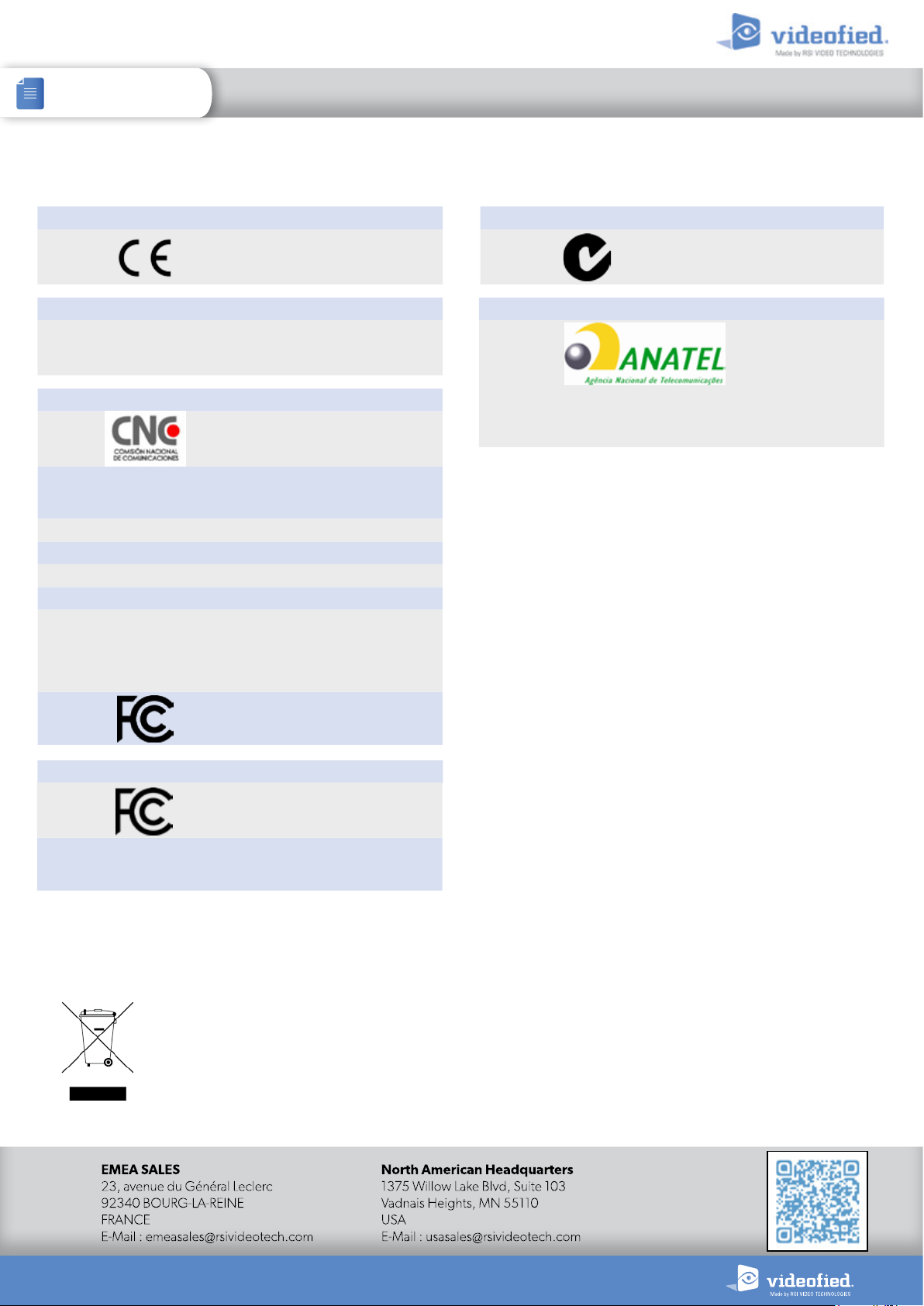
STANDARDS AND CERTIFICATIONS
XTO-iP 210 868 MHz
XTO-iP 733 915/928 MHz - FHSS
Europe
XTO-iP 310 865/867 MHz
India Certification in process
XTO-iP 630 902/928 MHz - FHSS
XTO-iP 630 902/928 MHz - FHSS
XTO-iP 630 902/928 MHz - FHSS
Argentina Certification number C-17498
Argentina Certification number C-17498
Argentina Certification number C-17498
Canada
Canada
Canada
Columbia Certification number : 2016866829
Columbia Certification number : 2016866829
Columbia Certification number : 2016866829
Costa Rica SUTEL 10029-2017
Costa Rica SUTEL 10029-2017
Costa Rica SUTEL 10029-2017
Mexico IFT Certification number RCPSISI17-0298
Mexico IFT Certification number RCPSISI17-0298
Mexico IFT Certification number RCPSISI17-0298
Panama Certification number : 1709
Panama Certification number : 1709
Panama Certification number : 1709
«En Perú, este equipo diseñado para la banda de 902-928MHz,
«En Perú, este equipo diseñado para la banda de 902-928MHz,
Peru
Peru
Peru
«En Perú, este equipo diseñado para la banda de 902-928MHz,
debe ser configurado para operar solo en la banda 915-928MHz
debe ser configurado para operar solo en la banda 915-928MHz
debe ser configurado para operar solo en la banda 915-928MHz
con una PIRE de hasta 1W (30dBm) y sujeto a las Condiciones de
con una PIRE de hasta 1W (30dBm) y sujeto a las Condiciones de
con una PIRE de hasta 1W (30dBm) y sujeto a las Condiciones de
Operación que establezca el MTC.»
Operación que establezca el MTC.»
Operación que establezca el MTC.»
Compliant with Directive 2014/53/EU for RED
Radio Equipment Directive
RSS-132, Issue 3, RSS-133, Issue 6,
RSS-132, Issue 3, RSS-133, Issue 6,
RSS-132, Issue 3, RSS-133, Issue 6,
RSS-139, Issue 3, RSS-247, Issue 1
RSS-139, Issue 3, RSS-247, Issue 1
RSS-139, Issue 3, RSS-247, Issue 1
Certification number TRRFM38411
Certification number TRRFM38411
Certification number TRRFM38411
Id: 8816A-XT06
Id: 8816A-XT06
Id: 8816A-XT06
Australia C-Tick
XTO-iP 830 902/907.5 MHz & 915/928 MHz
Certification Number
006231-16-10210
Brazil
Este equipamento opera em caráter secundário, isto é, não
tem direito a proteção contra interferência prejudicial, mesmo
de estações do mesmo tipo, e não pode causar interferência a
sistemas operando em caráter primário.
USA
USA
USA
XTO640
USA
Canada
FCC Part 15C, FCC Part 22H, 24E, 27
FCC Part 15C, FCC Part 22H, 24E, 27
FCC Part 15C, FCC Part 22H, 24E, 27
902/928 MHz - FHSS
FCC Part 15C, FCC Part 22H, 24E, 27
RSS-132, Issue 3, RSS-133, Issue 6,
RSS-139, Issue 3, RSS-247, Issue 1
This symbol on the product or on its packaging indicates that this product should not be treated as household waste. It must be handed
over to the applicable collection point for the recycling of electrical and electronic equipment. By ensuring this product is disposed of
correctly, you will help prevent potential negative consequences for the environment and human health. The recycling of materials will
help to conserve natural resources. For more information about recycling of this product, please contact your local municipality, your
waste disposal service or the company that installed the product.
Id: X46XT06
Id: X46XT06
Id: X46XT06
Id: X46XT07
Id: 8816A-XT07
www.videofied.com
The EC declaration
of conformity of this
product is available
by flashing this QR
code.
27
 Loading...