

Videofied XT-IP620 Setup Manual
Document #2029-XTIPIN
COMPLETE SETUP AND PROGRAMMING MANUAL
FOR
XT-IP620
*A Videofied CMA/XMA/WMB Alphanumeric Keypad or Frontel TMT2 is required for
programming and maintenance*
CMA
XMA
WMB

2012/1/9 Ed 1.1 Setup and Programming manual for XT-IP620 series
Table of Contents
Page
FCC 3
Installation Guidelines 4
Introduction 5
Initial Programming 6-15
Device Installation 16
Entering Badges and Access Codes 17-18
Choosing Siren Options 18
Disabling Monitoring 19
Ethernet Parameters and Testing 20
Testing Device RF Level 21
XTIP Power Chart 22
Arming Input Wiring Diagram 23
Testing to Central Station 24
Mounting Control Panel 25
Troubleshooting 26-28
After Initial Programming Flow Chart 29-30
Addendum 31-33
Battery Specifications 31
Finding Manufacture Week/Year 32
Event Log Ethernet Codes 32
Additional System Quick Codes 32
Replacing Device and Control Panel batteries 33
Checking Control Panel Firmware 33
2 | P a g e

2012/1/9 Ed 1.1 Setup and Programming manual for XT-IP620 series
Regulatory Information for USA and Canada
FCC Part 15.21 Changes or modifications made to this equipment not expressly approved by RSI
Video Technologies may void the FCC authorization to operate this equipment.
FCC Part 15.105 Class B
This equipment has been tested and found to comply with the limits for a Class B digital device,
pursuant to Part 15 of the FCC Rules. These limits are designed to provide reasonable protection
against harmful interference in a residential installation. This equipment generates uses and can
radiate radio frequency energy and, if not installed and used in accordance with the instructions,
may cause harmful interference to radio communications. However, there is no guarantee that
interference will not occur in a particular installation. If this equipment does cause harmful
interference to radio or television reception, which can be determined by turning the equipment off
and on, the user is encouraged to try to correct the interference by one or more of the following
measures:
Reorient or relocate the receiving antenna.
Increase the separation between the equipment and receiver.
Connect the equipment into an outlet on a circuit different from that to which the receiver is
connected.
Consult the dealer or an experienced radio/TV technician for help.
Radiofrequency radiation exposure information according 2.1091 / 2.1093 / OET bulletin 65
This equipment complies with FCC radiation exposure limits set forth for an uncontrolled
environment. This equipment should be installed and operated with minimum distance of 20 cm
between the radiator and your body.
This transmitter must not be co-located or operating in conjunction with any other antenna or
transmitter.
This device complies with Part 15 of the FCC Rules and with RSS-210 of Industry Canada.
Operation is subject to the following two conditions:
(1) this device may not cause harmful interference, and
(2) this device must accept any interference received, including interference that may cause
undesired operation.
3 | P a g e

2012/1/9 Ed 1.1 Setup and Programming manual for XT-IP620 series
Basic Setup Guidelines for Installation and Programming
Pre-Setup
1) Obtain the account number and IP/Domain information from the Central Station.
System Programming and Setup
1) Setup and program the system in the office or in your vehicle. DO NOT MOUNT THE DEVICES.
(Pages 6-15)
2) Add user codes and or badges after initial programming. (Pages 17-18)
3) Disable monitoring so that signals are not sent until you are ready to send them. (Page 19)
Deploying the System on Site
1) Place the panel where you want to mount it and run the Ethernet cable. In Maintenance run the ETH.
STATUS test to make sure you are receiving an IP. (Page 20)
2) Deploying Devices: Use your keypad to run the RF test for each device. If you get a 9/9 for your RF
test on the first device, then mount it. If not, you will need to move the device to get optimal signal.*
(Page 21)
3) Re-enable monitoring before you send signals (Page 19)
a. If you are currently using TMT Installer to program the system you can now take still pictures
from each MotionViewer using the software. See TMT Installer Users Manual available on
http://support.videofied.com
4) Once you have everything mounted, arm the system and trip one MotionViewer at a time. Make sure
you stand in front of each MotionViewer for 10 seconds so the central station has some video to look
at. (Page 24)
5) After you have sent signals to central station, call to verify.
The following pages will go through each one of these steps and, if you have any issues please consult the
troubleshooting section Pages 26-28. If you still cannot resolve the issue, please feel free to call technical
support through live support chat and ticket submission at support.videofied.com.
Sleeping mode and Wake-up on the CMA:
They keypad backlight will go out after 30 seconds of inactivity. When you press a button the keypad wakes up. The first touch on
the pad that wakes it up will not be a registered command and will only wake up the keypad.
Sleeping mode and wake-up on the XMA/WMB:
The keypad backlight will go out after 30 seconds of inactivity. The first touch on the keypad will wake up the keypad and will
register as a command to the control panel.
4 | P a g e

2012/1/9 Ed 1.1 Setup and Programming manual for XT-IP620 series
Type
Specifications
Location In Manual
Audio
When a MotionViewer is
installed on the system you
may not have the siren sound
for less than 60 seconds
Page 30
Audio
If no MotionViewer is installed
on the system you may not
have the siren sound for less
than 240 seconds
Page 30
Delays
When a MotionViewer is
installed on the system the
Entry delay must be 45 seconds
Page 9
In order for an installation to be UL compliant you must follow the
specifications in the table below:
Introduction:
Description:
The XT-IP620 control panel is a Videofied wireless, battery operated hybrid alarm system.
It is designed for residential, small business and commercial security applications. The XTIP620 provides integrated Video Verification and features an Ethernet communication
path.
The XT-IP620 has programmable inputs and outputs. XT-IP620 also features mapping
where an external input can be used to generate a video clip from a MotionViewer.
Supervised Wireless Technology:
The XT-IP620, along with all Videofied devices, uses the patented S2View® - Spread
Spectrum, Videofied, Interactive, AES Encrypted Wireless technology, providing
optimum signal integrity and security.
The bi-directional RF communication path between all devices and the system control
panel guarantees high signal reliability. Integrated antennas eliminate protruding wires or
rods, which are difficult to install, unsightly to consumers and potentially troublesome if
damaged.
The panel supervises every device (excluding the remote key fob) to validate current
open/close state, tamper condition, serial number, date of manufacture, firmware revision,
and battery status.
5 | P a g e
2012/1/9 Ed 1.1 Setup and Programming manual for XT-IP620 series
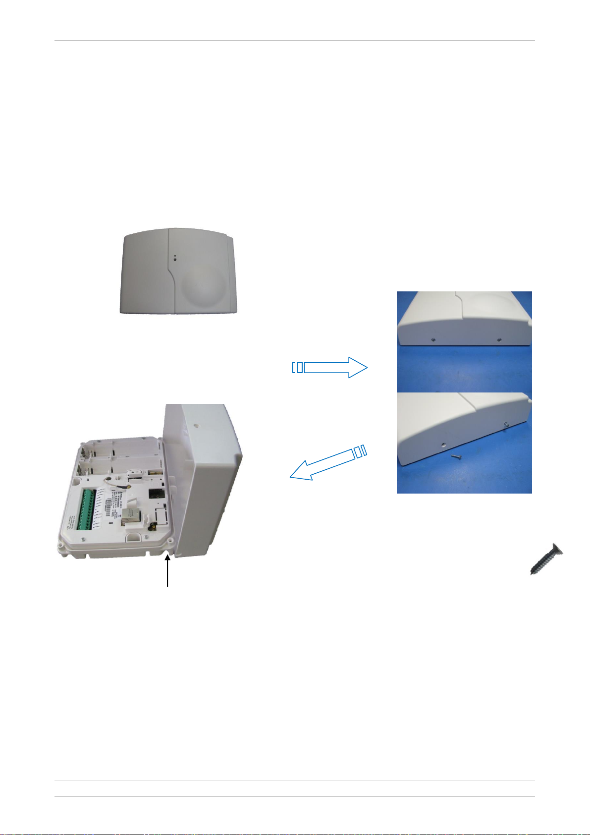
The cover will fold off the panel like a
book with the curved side acting like the
binding. The same technique is used
when placing the cover back onto the
unit.
Open the Control Panel
Using a #1 Phillips screwdriver, remove
the 2 screws holding the cover on.
SETUP MANUAL FOR
XT-IP620 SERIES PANEL
*THIS SYSTEM REQUIRES A CMA/WMB/XMA or TMT2 INSTALLER SOFTWARE FOR
PROGRAMMING*
**TO TRANSMIT ALARMS AND VIDEO VIA ETHERNET, THE SYSTEM REQUIRES AN
EXTERNAL POWER SUPPLY WITH 4 ALKALINE BATTERIES FOR BACK-UP (PP4)**
XT Initial Programming
6 | P a g e
2012/1/9 Ed 1.1 Setup and Programming manual for XT-IP620 series
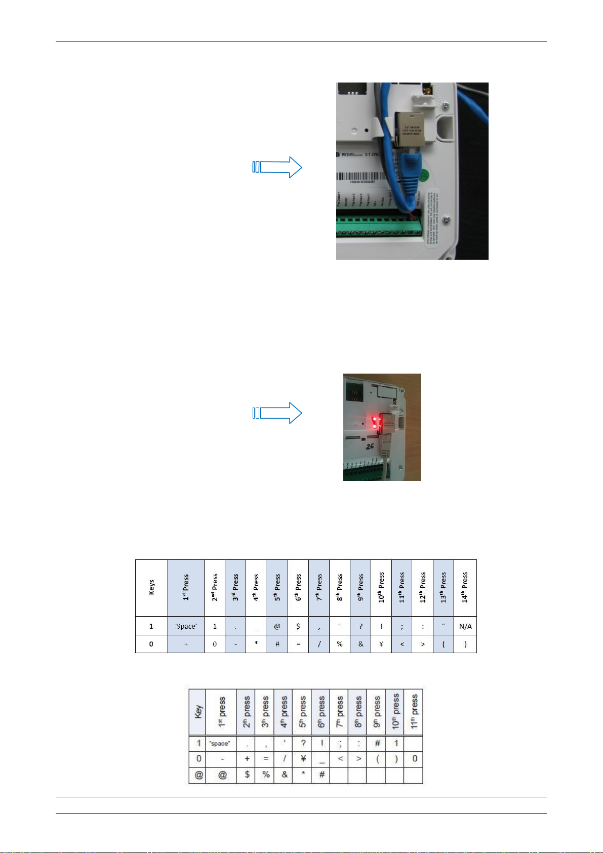
Obtaining WMB/XMA Keypad Special Characters
Obtaining CMA Keypad Special Characters
Connect the RJ45 (Ethernet
cable) to the panel
Plug the RJ45 cable into the
Ethernet jack on the control
panel. The cable can be routed
back through the wire channel to
make sure it does not get
pinched.
Important:
When the panel attempts a
transmission via Ethernet a
red LED will flash.
7 | P a g e
2012/1/9 Ed 1.1 Setup and Programming manual for XT-IP620 series
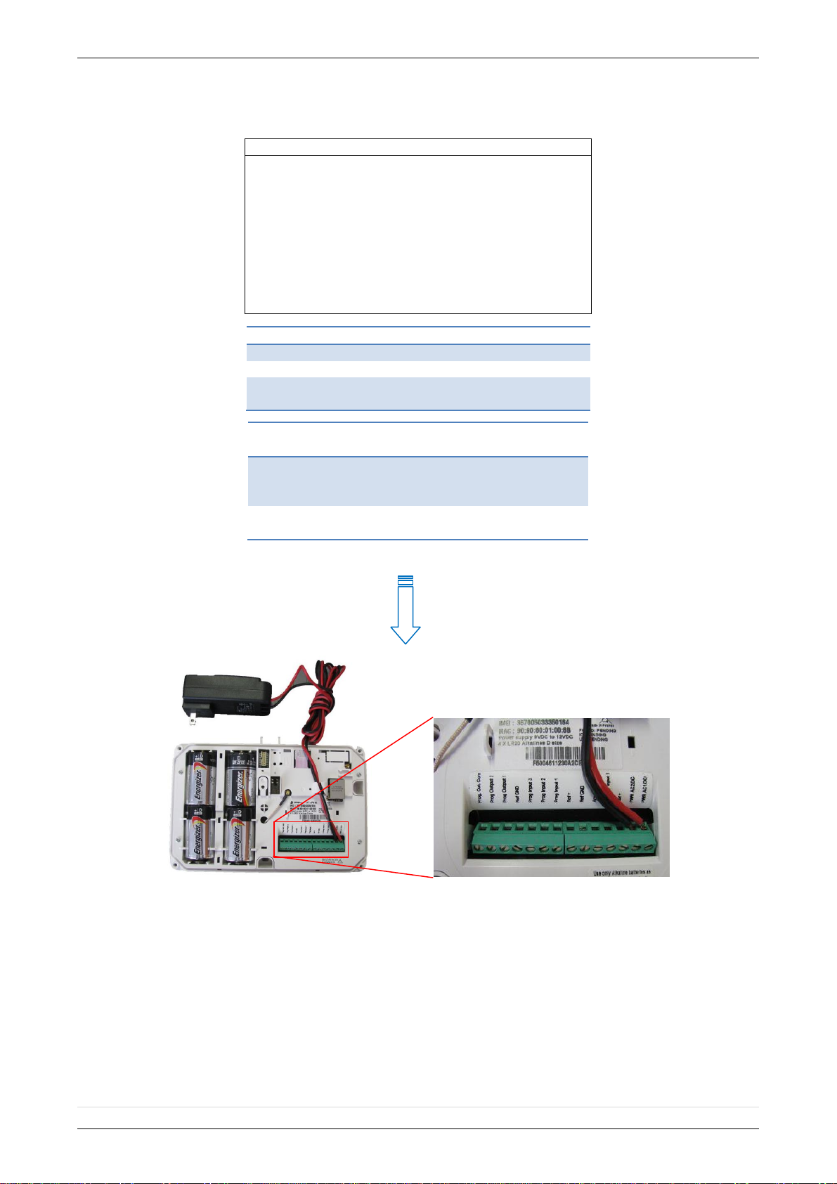
Power Option (PP4)
4 x E95VP Alkaline D-Cell + 12v 2amp DC Class 2
power supply (not supplied)
Used for Standalone or Xtender mode where
Programmable Inputs/Mapping, Programmable
Outputs, Ethernet connection, or SMS will be used
E95VP Specifications:
Operating Temp: 0°F to 130°F
Power Supply Requirements
Output Voltage (volts)
12
Output Current (mA)
2000
Certifications
Class 2 (For UL
Compliance)
E95VP Technical Specifications
Nominal Capacity
8900 mA hours
Nominal Voltage
1.5 V
WARNING:
1. DO NOT USE ALKALINE BATTERIES IF INSTALLING
BELOW 30° F
8 | P a g e
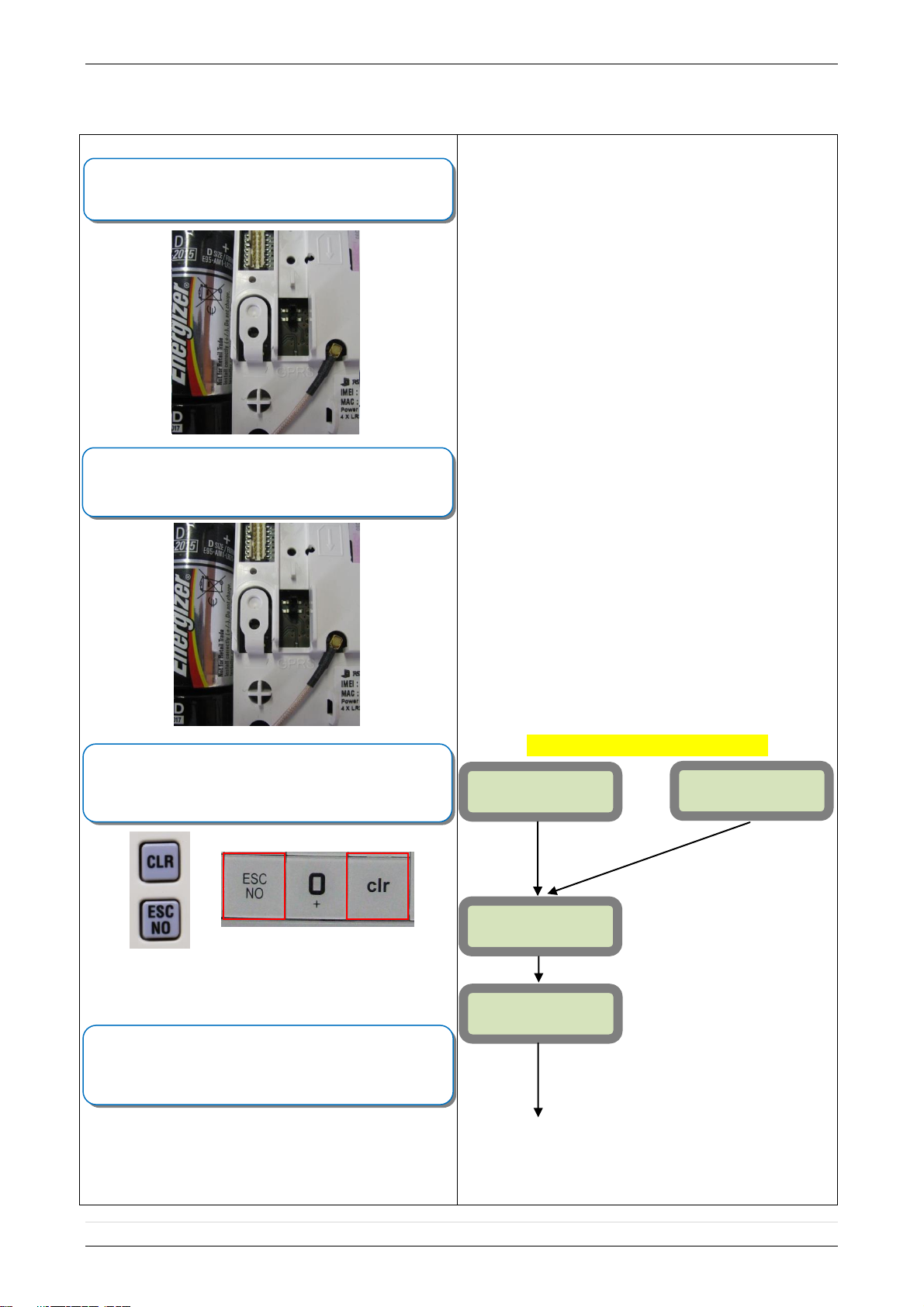
Programming Device/Keypad
or
Reset the XTIP Panel:
Press and hold programming button () for 10sec until the
Indicator LED blinks twice
Press and instantly release the programming button ().
The indicator LED will blink once. The panel is now in ‘Learn
Mode’ for the CMA/XMA/WMB keypad.
CLR & ESC/NO
<======XX======>
Insert all three batteries into the CMA/XMA/WMB and press
both the ESC/NO and CLR keys at the same time and
release.
The indicator LED on the keypad will blink rapidly.
YES/OK
KEYPAD 1
RECORDED
RSI (c)20##
www.RsiAlarm.com
<- LANGUAGE : ->
ENGLISH (US/AUS)
or for language selection
YES/OK to apply
Other languages are available by scrolling with arrows.
ITALIANO, NEDERLANDS, DEUTSCH, CASTELLANO,
SVENSKA, PORTUGUES, FRANCAIS
Press YES/OK for the selected one.
*NOTE: If you are having issues
pairing the keypad to the panel,
please refer to the troubleshooting
section.
*NOTE: Once a language is chosen
it cannot be changed in
programming.
2012/1/9 Ed 1.1 Setup and Programming manual for XT-IP620 series
XT-IP620 Programming
9 | P a g e
2012/1/9 Ed 1.1 Setup and Programming manual for XT-IP620 series
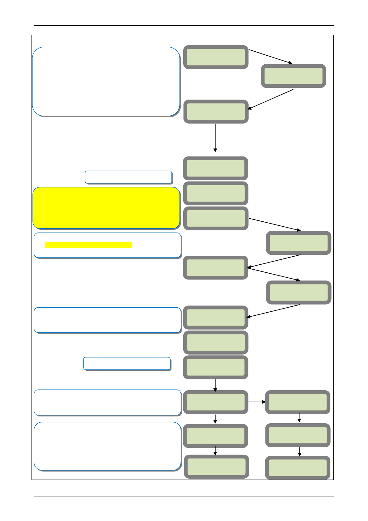
ENTER THE
INSTALLER CODE
4 TO 6 DIGITS
THEN YES/OK
INSTALLER CODE:
INSTALLER CODE:
xxxx
YES/OK
CONFIRM CODE
RE-ENTER CODE
CONFIRM CODE
xxxx
CODE NAME:
ACCESS 1
ENTRY COMPLETE
RADIO RANGE
TEST ?
RF TEST
x/9
YES/OK
ESC/NO
SETTING
DATE AND TIME
SETTING:
AUTO
SETTING:
MANUAL
DATE (Year) :
13/
DATE (Month) :
13/11/
YES/OK
YES/OK
Wait while the screen changes
Use the Alphanumeric Keypad to enter the Installer Code
*This code is important to keep track of. There is no back
door to the system
You may name the installer code using the Alphanumeric
Keypad. If you leave the name blank it will default to
‘ACCESS 1’
Use the or to choose between Auto and
manually configuring the Date and Time
Auto: You will use the arrow keys to choose the UTC time
zone that the panel will be installed at followed by the exact
location within the time zone.
Manual: Use the arrow keys to define the year/ Month/ Day/
Hour/ Minute.
RADIO RANGE
TEST ?
YES/OK
The Radio Range test must be run during device recording
to ensure proper pairing with the control panel. This test the
number of successful pings between the device and the
control panel. The keypad will display a real time RF level
for the device that is being tested. This test will run until
stopped and should be run for at least 30 seconds to
receive accurate results.
The RF level must be 9/9 for reliable transmission.
Wait while the screen changes
TIMEZONE:
UTC-05
From here until the end of initial programming
you will not be able to step back to a previous
parameter. All parameters can be changed after
initial programming has been completed.
YES/OK
UTC-06:
CENTRAL (US/CAN)
10 | P a g e
 Loading...