

Videofied XT GPRS Installation Manual

Monitored GPRS Cellular alarm system
Made by RSI VIDEO TECHNOLOGIES
Installation
Manual
Security System Videofied
®
- Model XT GPRS
XT GPRS -
XT600i GPRS for USA/Canada,
XT700i GPRS for Australia/New Zealand
200 i GPRS for Europe and rest of the world.
Video Alarm Technologies HELPLINE: 1300 46 44 55
info@videofied.com.au
Australasian Hotline +61 (0) 7 5
Video Alarm Technologies
SETUP MANUAL
FOR
XT710 GPRS PANEL
*THIS SYSTEM REQUIRES A CMA01 FOR PROGRAMMING*
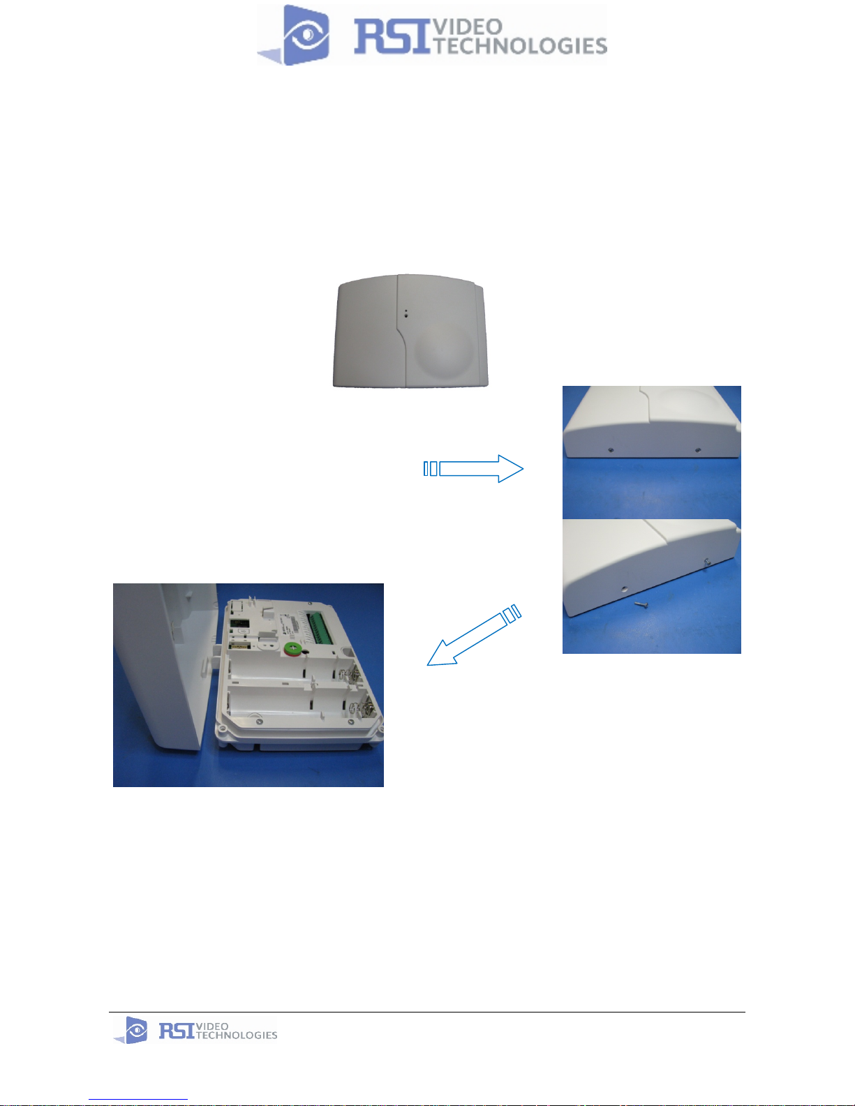
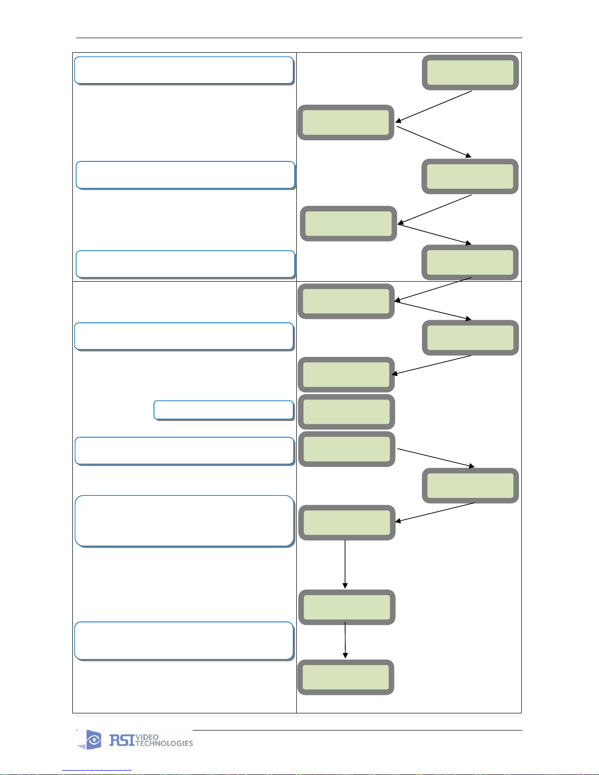
1. XT Installation
Open the Control Panel
Unscrew the 2 screws holding
the panel together
infor
info@videofied.com.au
www.videofied.com.au
2009/06/15 Ed1.0 User manual for XT710GPRS
2 | Page
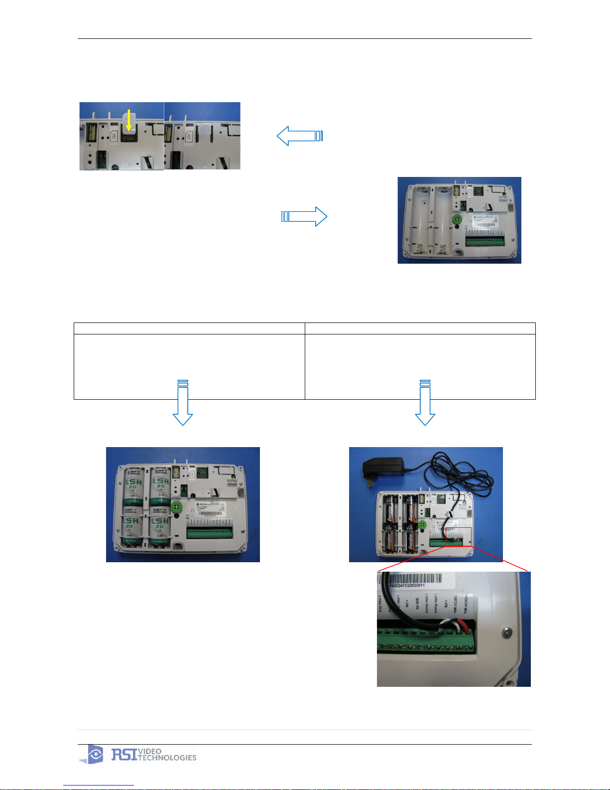
*The SIM card must not be inserted or removed while the panel is powered*
Install the SIM card
Put the SIM card on the plastic
(Take care to respect the right direction)
Slide it into the connector.
*How to Mount the Control Panel
Fix the back casing on the wall
with 3 screws (n top).
*Mounting does not have to be performed
in-order to program the panel.
Power the XT panel
Option 1: Option 2:
4 x LSH20 Lithium D-Cell
Used for Standalone or Xtender mode without
Programmable Inputs. (inputs may be used if N/O)
4 x E95 Alkaline D-Cell + 12DC power supply
Used for Standalone or Xtender mode where
Programmable Inputs/Mapping will be used
n
o
p
2009/06/15 Ed1.0 User manual for XT710GPRS
3 | Page
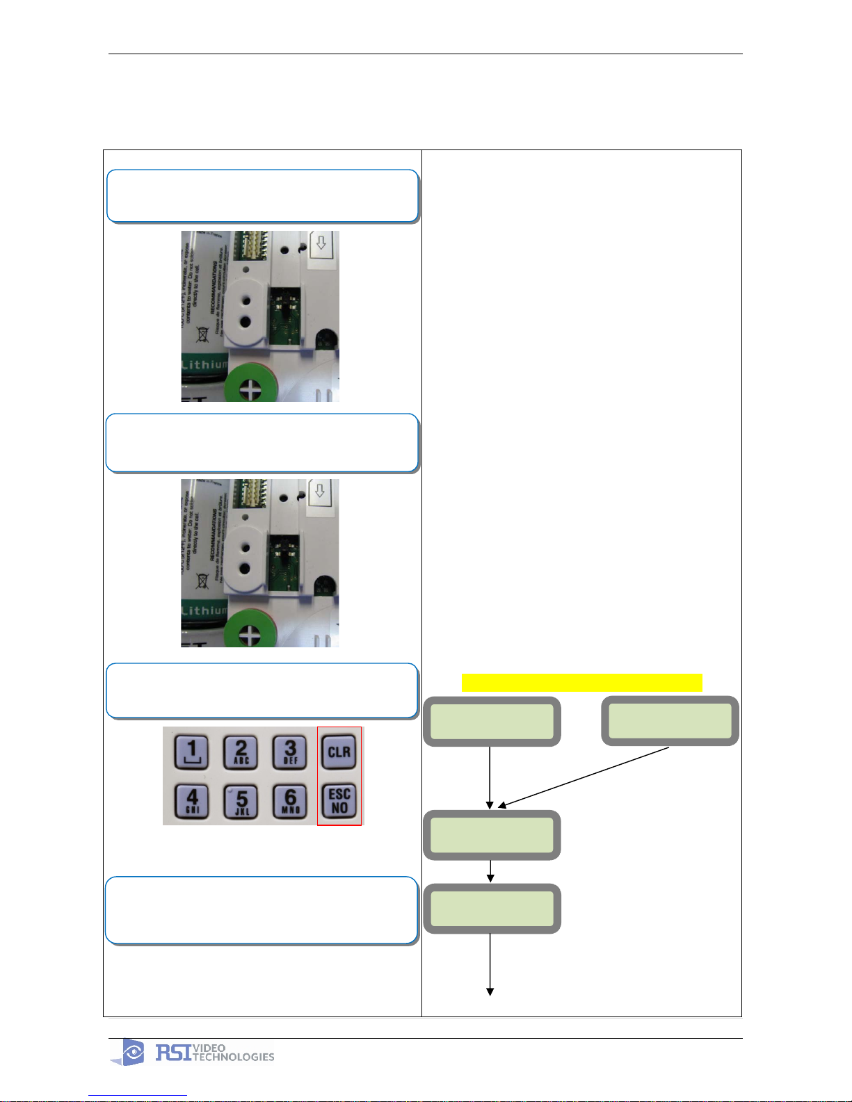
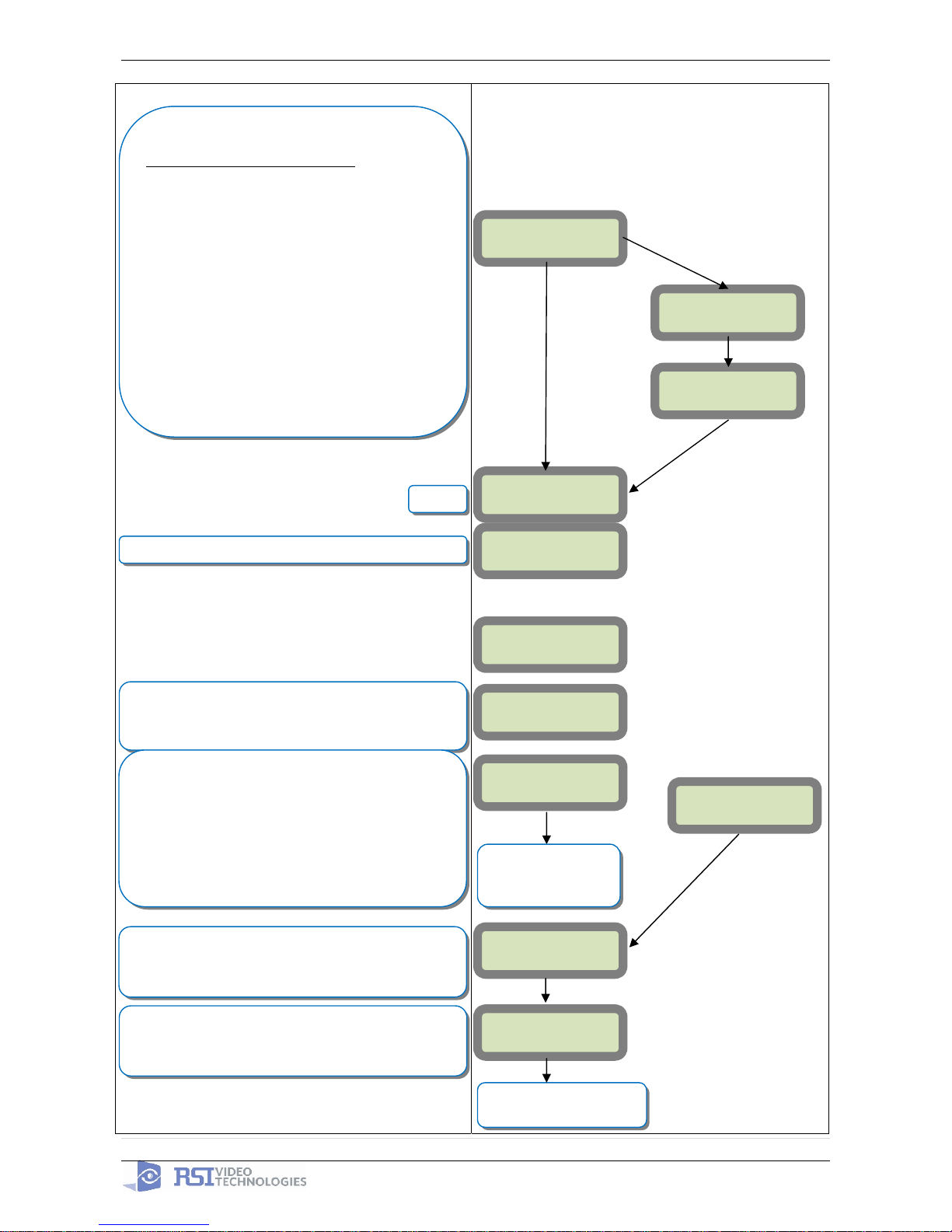
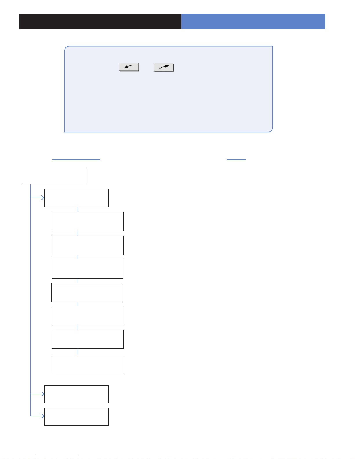
2. XT Programming
CMA Programming Device/Keypad
or
Reset the XT Panel :
Press and hold programming button (
n) for 10sec until the
Indicator LED blinks twice
Press and instantly release the programming button (n).
The indicator LED will blink once. The panel is now in ‘Learn
Mode’ for the CMA701 keypad.
CLR & ESC/NO
≤======XX======>
Insert all three batteries into the CMA701 and press on both
the ESC/NO and CLR keys at the same time and release.
The indicator LED on the keypad will blink rapidly.
©YES
KEYPAD 1
RECORDED
RSI (c)2005
www.RsiAlarm.com
<- LANGUAGE : ->
ENGLISH
Õ or Ö for language selection
©YES to apply
Other languages are available by scrolling with arrows.
ITALIANO, NEDERLANDS, DEUTSCH, CASTELLANO,
SVENSKA, PORTUGUES, FRANCAIS
Press YES for the selected one.
n
n
2009/06/15 Ed1.0 User manual for XT710GPRS
4 | Page
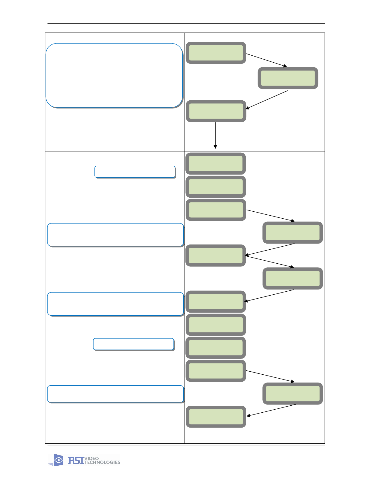
ENTER THE
INSTALLER CODE
4 TO 6 DIGITS
THEN YES
INSTALLER CODE:
INSTALLER CODE:
xxxx
©YES
CONFIRM CODE
RE-
ENTER CODE
CONFIRM CODE
xxxx
CODE NAME :
ACCESS 1
ENTRY COMPLETE
RADIO RANGE
TEST ?
RF TEST
x/9
©YES
ESC/NO
ADJUSTING
TIME AND DATE
DATE (Year) :
09/ /
DATE (Year) :
10/ /
DATE (Month) :
10/01/
The Radio Range test must be run during the learn in
process in order to ensure proper pairing with the control
panel. This test is the strength of communication between
the device and the control panel. The keypad will display a
real time range out of 9 for the device that the test is
running for. To receive the most accurate results you must
run the radio range test for at least 30 seconds.
The RF level test must be 8/9 or better for reliable
transmission.
©YES
RADIO RANGE
TEST ?
©YES
©YES
Wait while the screen changes
Use the Õ or Ö to set the Year
You may name the installer code using the Alphanumeric
Keypad. If you leave the name blank it will default to
‘ACCESS 1’
Use the Alphaumeric Keypad to enter the Installer Code
*This code is important to keep track of. There is no back
door to the system
Wait while the screen changes
2009/06/15 Ed1.0 User manual for XT710GPRS
5 | Page
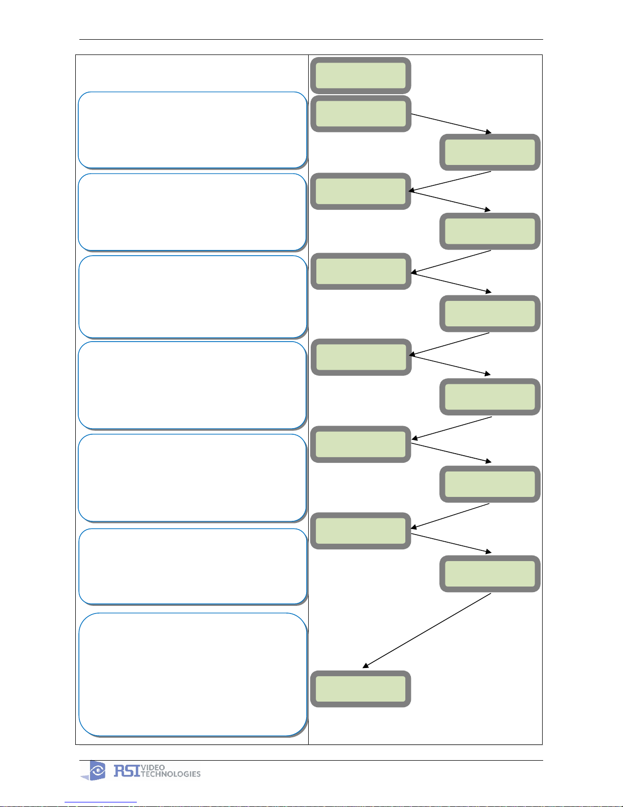
DATE (Minutes) :
10:00
DATE (Minutes) :
10:53
03/06/09 10:53
ENTRY COMPLETE
CONNECTED TO
MONITOR.STATION?
ACCOUNT NUMBER?
ACCOUNT NUMBER:
99865123
PERIODIC TEST:
24 HOURS
Other periods are available:
48 hours, 24 hours, 12 hours,1 hour, No Test
Use arrows for the selection and press
©YES to confirm.
*We suggest at least a 24 hour test
Õ or Ö for period selection
and
©YES to apply
DATE (Month) :
10/11/
DATE (Day) :
09/06/01
DATE (Day) :
09/06/03
©YES
©YES
©YES
Using the arrow keys + ©YES to choose the Hour and
Minute the periodic test will happen.
TEST MINUTE:
00:00
TEST HOUR:
00:00
Use the Alphanumeric Keypad to enter in a 4-8 digit account
number provided by the Central Station
Use the Õ or Ö to set the Hour
Use the Õ or Ö to set the Minutes
©YES
TIME (HOUR) :
00:00
YOU MUST ALWAY CHOOSE ‘YES’
©YES
TIME (HOUR) :
10:00
Use the Õ or Ö to set the Day
Use the
Õ or Ö to set the Month
2009/06/15 Ed1.0 User manual for XT710GPRS
6 | Page
CODE/STATE
MODIFICATION ?
ENTER YOUR
I.D.
NAME OR ADDRESS
AREAS
CONFIGURATION
AREA NAME 1:
Other values are available:
2 min, 1 min, 45 sec
Use the arrows for the selection and
©YES to confirm.
Other values are available:
2 min, 1 min, 45 sec, 30 sec, 15 sec
Use the arrows for the selection and
©YES to confirm.
Use the Alphanumeric Keypad to name the area and press
©YES. Repeat for all areas. If you want to keep the default
area names press the ESC/NO key.
CODE/STATE modification
These are the default transmitted events
:
Intrusions
Panic
Periodic Test
Tamper
Supervision Fault
Device Battery Low
Panel Battery Low
If you would like any other events to be transmitted
press
©YES and use the Õ or Öto toggle
between events
If you would like the default press ESC/NO
You may name the Site
Wait
TRANS. STATE
MODIFICATION
List of all
events
©YES
ESC/NO
©YES
EXIT DELAY:
45 Sec
ENTRY DELAY:
15 Sec
ARMING OPTION:
From the host
ARMING OPTION:
Standalone
ARMING OPTION: You will choose between configurations
depending on how you will be arming the system.
From the host: Will make the XT a piggyback/xtender
system that arms and disarms off the latching of 9-12v on
the arming inputs.
Standalone: Will make the XT a solo system controlled by
arming and disarming using Videofied peripheral devices.
Ö
Go to Page 7 if you will
be choosing this option
Go to Page 8 to continue with
standalone programming

2009/06/15 Ed1.0 User manual for XT710GPRS
7 | Page
©YES
Ö
Ö
Ö
Ö
Ö
ARMING OPTION :
From The Host
MODE:
Slow
MODE:
Fast
Mode Slow : Used for following the arming and disarming of
the host system. This will arm each device one at a time
conserving battery life.
Mode Fast : Used to instant arm all devices while sacrificing
battery life.
ENTRY DELAY
There is no Videofied Exit Delay with the ‘From the Host’
option. Videofied will only control the Entry Delay.
Enter the value for your Entry Delay up to 255 seconds and
press
©YES.
VALUE:(0-255)
(000):
Ö
TRANSMISSION
DELAY
Value: (0-600)
(000):
ARMING
CONFIRMATION
©YES
Value: (0-5)
(0-
5):
©YES
©
YES
©YES
©YES
By entering a value using the keypad, up to 600 seconds,
the transmission of any event will be delayed that many
seconds.
Enter the value you would like for the Transmission Delay
and press
©YES
Arming Confirmation is the number of seconds of latched
voltage (where voltage must stayed latched after) the panel
will require before arming.
Enter the value you would like for the Arming Confirmation
and press
©YES
©YES
Using the control panel as a Xtender system will only be able to arm and disarm by latching 9-12vDC to
one of the two inputs.
Arming input 1 will control the arming and disarming of devices in areas 1 and 2. Where devices in
area 1 are subject to the Entry Delay.
Arming input 2 will control the arming and disarming of devices in areas 3 and 4. Where devices in
area 3 are subject to the Entry Delay.
2009/06/15 Ed1.0 User manual for XT710GPRS
8 | Page
©YES
Ö
Ö
Ö
Ö
Ö
GPRS
PARAMETERS ?
APN CODE
APN CODE:
xxxxx.xxxxxx.xxx
Your APN code (Access Point Name) is given to you by your
SIM card Provider. Press
©YES to enter into the parameter
and use the Keypad to complete the code. Press
©YES to
confirm your entry and the
Öarrow to move to the next
parameter.
USERNAME
PASSWORD
Your USERNAME is given to you by your SIM card Provider.
Press
©YES to enter into the parameter and use the
Keypad to complete the name. Press
©YES to confirm
your entry and the
Öarrow to move to the next parameter.
PASSWORD:
xxxxxxxxxxxx
USERNAME:
xxxxxxxxxxx
©YES
IP1 ADDRESS
IP1 ADDRESS:
xxx.xxx.xxx.xxx
DOMAIN NAME 1
©YES
DOMAIN NAME 1:
xxxxx.xxx.xxx
PORT 1
PORT 1:
xxx
©YES
©
YES
©
YES
©
YES
Your PASSWORD is given to you by your SIM card Provider.
Press
©YES to enter into the parameter and use the
Keypad to complete the name. Press
©YES to confirm
your entry and the
Öarrow to move to the next parameter.
Your IP1 address is given to you by your Monitoring Station.
Press
©YES to enter into the parameter and use the
Keypad to complete the address. Press
©YES to confirm
your entry and the
Öarrow to move to the next parameter.
*You will use either a IP address or a Domain Name but not
both
Your Domain Name is given to you by your Monitoring Station.
Press
©YES to enter into the parameter and use the
Keypad to complete the name. Press
©YES to confirm
your entry and the
Öarrow to move to the next parameter.
*You will use either a IP address or a Domain Name but not
both leave it blank if an IP has already been entered.
The Port is given to you by your Monitoring Station. By default
the panel will use 888. If you need to modify the port press
the
©YES key to enter into the parameter and the keypad
to complete the port. Press
©YES to confirm and the
Öarrow to move to the next parameter.
GPRS PARAMETERS?
The Port is given to you by your Monitoring Station. By default
the panel will use 888. If you need to modify the port press
the
©YES key to enter into the parameter and the keypad
to complete the port. Press
©YES to confirm and the
Öarrow to move to the next parameter. Continue through
IP2 and TMT IP.
Once you have entered all valid parameters press ESC/NO
to return to the main menu then ESC/NO again to move to
the
next parameter.
ESC/NO
ESC/
NO
2009/06/15 Ed1.0 User manual for XT710GPRS
9 | Page
3. Other XTi setup with CMA701 keypad (Standalone ONLY)
Other setup (badges/codes, arming profiles, etc…) must be set with the CMA keypad
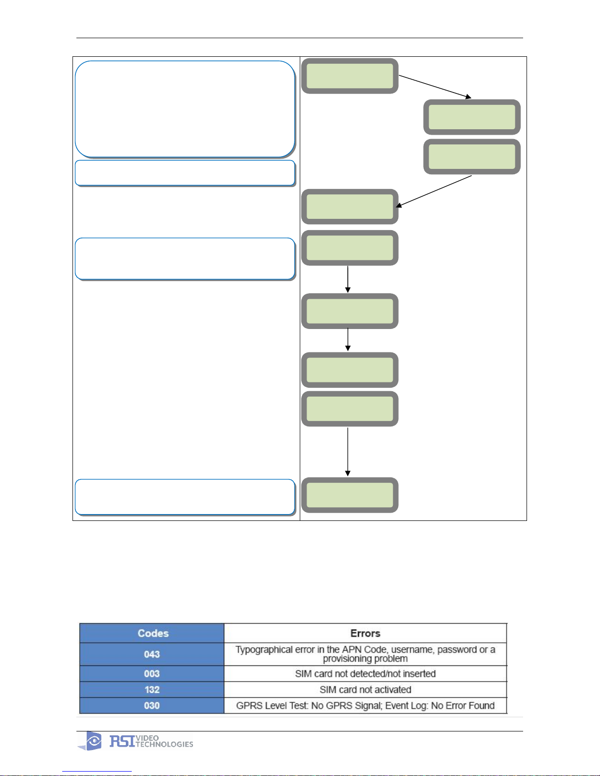
4. GPRS error codes
GPRS LEVEL?
TEST IN PROGRESS
YES = END
GPRS LEVEL
x/5
Videofied will require a 3/5 or better for reliable transmission
of Video alarms
During the GPRS Level test the Modem will boot and
attempt to gain access to the internet to post a Level out of
5 or an error Code that will help troubleshoot why it cannot
connect. To keep the keypad awake use any keys on the
keypad except the YES, ESC/NO, and CLR keys. This test
can take up to 5 minutes. Once the level or error has
posted press YES to continue in programming.
*For explanation of GPRS errors see page 9
RECORDING
DEVICES
Each device has a unique programming button. Please
reference the Installation Sheet for the device you would like
to program.
PRESS PROGRAM
BUTTON OF DEVICE
ENTERING A NEW
DEVICE?
END OF
CONFIGURATION
CLOSE THE PANEL
©
YES or ESC/NO
©
YES
©
YES
OPERATION
COMPLETED?
©YES
Before completing programming make sure that all tampers
are depressed by verifying that each devices indicator LED is
off

APN Technical Note:
SIM Card Service
Provider
APN
Username & Password
Fields
Telstra public
telstra.wap OR
telstra.internet
*BLANK*
Telstra Private
telstra.corp
Required (case sensitive)
Vodafone (AUS)
vfinternet.au
*BLANK*
Vodafone (NZ)
internet
*BLANK*
Optus
internet
*BLANK*
Access Point Name (APN) is a configurable network identifier used by mobile devices when
connecting to a GSM/GPRS carrier. This APN – network identifier is specific to the SIM card
service provider. See a list of APN’s that relate to common Australian/New Zealand Sim card
service providers.
The GPRS Parameters – Settings of Videofied require the APN to be entered in lower case.
If the SIM card service is being used on the Public Network, then the USERNAME and
PASSWORD fields are to be left blank.
If the SIM card service is being used on the Corporate – Private Network, then the USERNAME
and PASSWORD MUST be entered to communicate to the monitoring station. These entries are
case sensitive. The username and password is to be provided by your SIM card provider or your
monitoring station.
APN - Australian / New Zealand
GPRS Parameters APN Technical Note PAGE 10

PROGRAMMABLE INPUTS
APPLICATION NOTE
Made by RSI VIDEO TECHNOLOGIES v.E 1.0
XT700i GPRS control panels are wireless battery operated alarm systems designed for residential, small business security applications and
both indoor and outdoor commercial applications. Through the use of the MotionViewer and Videoed products, the XT700i GPRS panel
offers video verication in case of intrusion.
The XT control panel has three programmable inputs. Note that we advise to use a power supply when using the programmable inputs.
The XT control panel can either be used as a STANDALONE or XTENDER (piggyback) to an exisiting alarm panel.
This application note will focus on the conguration and the use of this programmable inputs. You will be able to program your
programmable input(s) by reading the Conguration section. The Use section will get you an idea of the practical use of programmable
inputs.
PROGRAMMABLE INPUT 1, PROGRAMMABLE INPUT 2 and PROGRAMMABLE INPUT 3 are triggered by voltage between 9V
and 15V and an intensity between 1,5mA (@9V) and 3mA (@15V). If a dry contact is used to trigger the programmable inputs, the
REF+output can be used to supply this dry contact. (See Diagram Page 3 - PROGRAMMABLE INPUT 1 is set up as a panic button).
The XT control panel also offers a mapping feature. Mapping option allows the input to generate a video-clip via a MotionViewer
when a programmable input is triggered and/or when an event occurs. (See Mapping Application note) An obvious application for this
feature is HoldUp alarm event video verification.
Please note that programmable inputs can be allocated to events such as:
INTRUSION Intrusion event. With siren by default.
TAM PER Tamper event. With siren by default.
PANIC BUTTON Panic Button event. With siren by default.
INCORRECT CODE Incorrect code event. With siren by default.
DURESS CODE1 Duress code event. Without siren by default.cto.
DURESS CODE2 Duress code event. With siren by default.
SUPERVISION Supervision defect event. Without siren by default.
RADIO JAMMING Radio jamming event. Without siren by default.
LOW PANEL BATT. Low panel batteries event. Without siren by default.
LOW DEVICE BATT. Low device batteries event. Without siren by default.
AC POWER MISS. AC Power missing event. Without siren by default.
PANEL R ESE T Panel reset event. Without siren by default.
SYSTEM ARMED System armed event. Without siren by default.
SYSTEM DESARMED System desarmed event. Without siren by default.
PERIODIC TEST Periodic test event. Without siren by default.
ALARM CANCEL Alarm cancel event. Without siren by default.
SMOKE DETECTION Smoke detection event. With siren by default.
PHONELINE MISS. Phoneline missing event. Without siren by default.
TMT REQUEST TMT request event. Without siren by default.
www.videofied.com.au
1. Configuration : programmable inputs
PROGRAMMABLE INPUTS CONFIGURATION
(Use and to change values)
1.ACCESS LEVEL + YES
2.ACCESS LEVEL : 4 + YES
3.ENTER YOUR INSTALLER BADGE OR CODE + YES
4.CONFIGURATION + YES
5.ENTER YOUR INSTALLER BADGE OR CODE + YES
6.GENERAL PARAMETERS + YES
7.PROGRAMMABLE INPUTS + YES
Keypad screen
PROGRAMMABLE
INPUTS
PROGRAMMABLE
INPUT 1
TRANSMISSION : ENABLED//
DISABLED//ONLY IF ARMED
ALARM MODE : ALARM //
ALARME / END
INPUT TYPE : NORM. OPEN
// NORM. CLOSED
EVENT TYPE
INPUT NAME
Notes
Programmable Inputs conguration menu
Programmable Input 1 conguration menu
Programmable Input 1 status conguration. ENABLED : PROGRAMMABLE INPUT
EN AB LED // DISA B LED : PR OG R A MM A B L E IN PUT DISA BLED // ON LY IF AR MED
: PROGRAMMABLE INPUT works only if the system is armed.
Alarm Mode conguration. ALARM : From the start of the event - Open . ALARM /
END : From the start of the event, as well as from the end of the event – OPEN /
CLOSE.
Programmable Input type conguration. NORMALLY OPEN : Your programmable
input is open by default. NORMALLY CLOSED: Your programmable input is close
by default.
Event type choice. (See Event Type list in Page 1)
Programmable input name choice
SIREN MODE : SIREN //
SILENT // WITHOUT SIREN
MAPPING : DISABLED //
CAMERA NAME
PROGRAMMABLE
INPUT 2
PROGRAMMABLE
INPUT 2
Siren mode choice when programmable input is triggered. SIREN : Siren enabled.
SILENT: Siren disabled. WITHOUT SIREN : Siren disabled however beep on keypad
enabled.
The Mapping feature allows to generate a video-clip via a Motion Viewer when
a programmable input is triggered and/or when an event occurs. DISABLED :
MAPPING disabled. CAMER A NAME : Camera choice generating video-clip.
Programmable Input 2 conguration menu
Programmable Input 3 conguration menu
www.videofied.com
 Loading...