


XT200i QUICK SETUP GUIDE
Description
The XT control panel is a Videofied wireless, battery operated hybrid alarm system.
It is designed for residential and small business security applications, as well as both
indoor and outdoor commercial applications (construction sites, cell tower, remote
sites, substations...).
XT can be used as a standalone alarm system or can be integrated into an existing
alarms system as an upgrade to Videofied features and technology.
XT has programmable inputs and outputs (outputs available Q1 2011). Programmable
inputs and certain event types can be configured to capture video from a
MotionViewer device using the mapping feature.
The control panel has two easy to access external connectors for upgrading GPRS and
RF antenna connections.

Standalone Mode
In Standalone mode, the XT Panel work as full standalone alarm system with 25
wireless Videofied devices, 3 programmable inputs and 2 programmable outputs.
XTender Mode
In XTender mode, the XT Panel will extend the existing alarm system to include
Videofied as video verification and can also work as GPRS cell back-up.
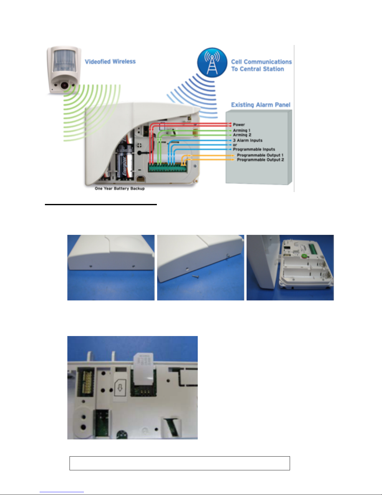
XT PANEL INSTALLATION
1. Unscrew the 2 screws at the side of the panel to open the control panel.
2. Insert the sim card into the provided slot.
Note: Do not insert or remove the sim card when the panel is

3. Mount the back casing to the wall with 3 screws (1 to 3)
*mounting is not necessary in order to program the panel.
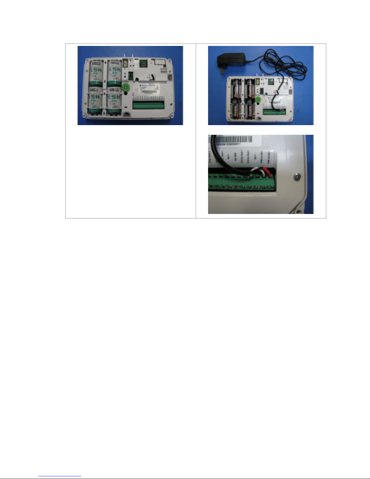
4. Powering the XT Panel
Option 1
Option 2
4 x LSH20 Lithium D-Cell
Used for Standalone or Xtender mode
without Programmable Inputs.
4 x E95 Alkaline D-Cell + 12DC power
supply
Used for Standalone or Xtender mode
where Programmable Inputs/Mapping
will be used.
213

XT PANEL PROGRAMMING
1.
Reset the XT Panel. Press and hold the
Programming Button for 10 seconds until the
LED blinks twice.
Press and release the Programming Button
again. The LED will blink once. The panel is now
waiting to pair with CMA200W Wireless keypad.
2.
Insert the batteries into CMA200W. The keypad
will beep twice. Press both ‘ESC/NO’ and ‘CLR’
keys at the same time. Release the keys.
The LED on the keypad will blink rapidly.
3.
The keypad will display ‘KEYPAD 1 RECORDED’ if
pairing is successful. If pairing is not successful,
repeat step 2.
Press the YES key.
4.
Press the left or right arrow on the keypad to
choose your language.
Press the YES key to confirm your selection.
5.
The keypad will display ‘RADIO RANGE TEST’.
Run this test to ensure proper pairing with the
control panel.
Press the YES key. The keypad will beep
continuously during this test. Run this test for at
least 30 seconds for accurate results.
Press the YES key, then ESC/NO to end this test.

6.
Key in 4-6 digits installer code and press the YES
key.
Key in the same 4-6 digits installer code to
verify and press the YES key.
You m ay na me th e i ns tal le r c ode . L ea ve bl an k
for default (ACCESS 1) and press the YES key.
7.
The Keypad will display ‘ADJUSTING TIME AND
DATE’
Wait for the screen to change to ask for
DATE(Year):
Use the left and right arrow key on the keypad
to change the value. Press the YES key to
confirm.
Repeat the same steps for others
8.
The keypad will display the current date and
time and ‘ENTRY COMPLETE’.
Press the YES key to continue.
9.
The keypad will display ‘CONNECTED TO
MONITOR. STATION?’. You must press the YES
key to enable GPRS reporting.

10.Key in 4-8 digit account number provided by the
Central Station.
Press the YES key.
Use the left and right arrow keys to select the
frequency of periodic test and press the YES key
to continue.
Use the left and right arrow keys to select the
hour the periodic test will happen. Press the
YES key to confirm. Repeat the same step for
minute.

11.The keypad will display ‘CODE/STATE
MODIFICATION?’.
If you would like any other events to be
transmitted, press the YES key.
Press the ESC/NO key to accept the default.
Manually Enable/Disable events that are
reported:
CONFIGURATION > CONFIGURATION
MONITOR.STATION > ALARM CODES > TRANS.
STATE MODIFICATION > select which events to
be transmitted:
Alarm – Only Appearance is transmitted
Alarm/End – Both Appearance and Restoral sent
Not Transmitted – Not Transmitted
12.Use the keypad to name the area 1. Leave blank
for default (Area 1) and press the YES key to
confirm.
Repeat the same step for the remaining areas.
13.Choose the arming option depending on the
configurations.
FROM THE HOST: The XT Panel will be on
XTender mode that arm/disarm off the latching
9-12V on the arming input.
STANDALONE: The XT Panel will be a single
system. Arm/disarm will be controlled by
Videofied devices (Wireless keypad, remote
control etc).
Press the YES key to continue.
*If you selected ‘FROM THE HOST’, please skip
to step 15.
The default transmitted
events:
Intrusions Panic. Periodic
Te s t , Ta mp er, S up er vi si on
Fault, Device Battery Low.
Panel Battery Low.

14.Use the left and right arrow keys to set the Exit
Delay time and press the YES key to continue.
Repeat the same step for Entry Delay.
*Proceed to step 16.

15.XTender Mode
In XTender Mode, control panel will only arm/
disarm by latching 9-12V to one of the two
inputs.
Arming input 1: Arming/disarming Area 1 & 2.
Entry delay on Area 1.
Arming input 2: Arming/disarming Area 3 & 4.
Entry delay on Area 3.
Choose an arming mode.
Slow: Follows the arming/disarming of host.
This will arm each device one at a time to
conserve battery.
Fast: Instant arm all devices. Sacrifices battery
life.
Enter a value for Entry Delay and press the YES
key. (Max: 255 seconds)
*No Exit Delay when using XTender Mode.
Enter the amount of time any event will be
delayed before transmission and press the YES
key.
(Max: 600 seconds)
For ‘ARMING CONFIRMATION’, select the amount
of time of latched voltage the panel requires
before arming and press the YES key. (0-5
seconds)

16.The keypad will display ‘GPRS Parameters?’
Press the YES key.
Enter the APN code (Access Point Name) as
given by the SIM card provider and press the YES
key to confirm. Use the left and right arrow
keys to scroll to scroll to other parameters.
Repeat the above steps for Username,
Password, IP1 address and Port 1. By default,
Port 1 is 888.
For IP address, enter in 3 digits format. Ie:
49.1.222.11 must be entered as
049.001.222.011
When done, press the ESC/NO key to go back to
previous menu.
Press the ESC/NO key again.
17.The keypad will display ‘GPRS LEVEL?’. Press
the YES key to begin the test.
During test, to keep the keypad awake, press
the left or right arrow keys.
If the test is successful, it will display the signal
level. GPRS signal need to be 3/5 or better for
reliable transmission.
Press the YES key.

ADDING USER CODE
18.The keypad will display ‘PRESS PROGRAM
BUTTON OF DEVICE’.
Press the Programming Button on the device you
want to pair.
The keypad will display ‘CAMREA 1 RECORDED’.
Press the YES key.
They keypad will display ‘RADIO RANGE TEST?’.
Press the ESC/NO key.
Select AREA: 1 for Area Allocation. Press the YES
key.
You ma y n ame th e c a me ra. Le ave bl an k fo r
default (CAMERA 1).
Press the ESC/NO key for the Functional test.
The keypad will display ‘ENTERING A NEW
DEVICE?’. Press the YES key to add more
devices.
Press the ESC/NO key to end.
19.The keypad will display ‘OPERATION
COMPLETED?’.
Press the YES key to confirm.
*Make sure the panel is closed and all the
devices’ tampers are depressed before
completing programming.
The keypad will display ‘INSTALLATION
SUCCESSFUL’.
20.Ena

1. Press the Right arrow key until you reach ‘BADGES ACCESS CODES’ and presses
the YES key.
2. Key in the installer code and press the YES key.
3. The keypad will display ‘ENTER A BADGE/CODE’. Press the YES key.
4. Key in the user code and press the YES key.
5. Key in the same user code again and press the YES key to confirm.
6. Name the code or leave blank for default (ACCESS 2).
GPRS ERROR CODES
CODES
Errors
043
Typographical error in the APN Code, username, password or a provisioning
problem
003
Sim card not detected/not inserted
132
SIM card not activated
030
GPRS Level Test: No GPRS Signal; Event Log: No error Found
 Loading...