

Page 1
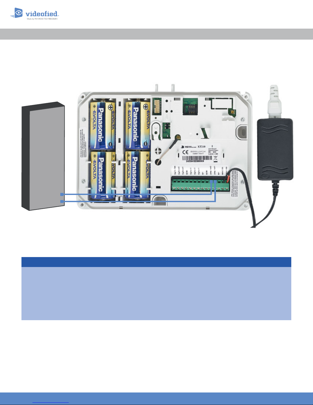
Existing Host
Panel
XTENDER Mode
APPLICATION NOTE
Doc. - Ref. 240 -XT
Version : March 2014
Arming O/P 2
Arming O/P 1
Index
1. Introduction Page 2
2. Arming and disarming from 9-12 VDC Page 3
2.1 Master system with external 12 VDC
2.2 Master system with dry contact
3. Arming and disarming from a X T master system. Page 5
Page 4
Page 4
www.videofied.com
1
Page 2

1. Introduction
The XT Videofied® alarm panel and its variants can be used as standard
standalone alarm system but it can also be connected to an existing alarm system
capable of latching a 9-12 VDC voltage used for its arming/disarming.
Thanks to a electrical relay. the the XT panel can also arm or disarm other XT
panels. The panel can also be armed by a master system or an external power
supply with a switch.
This application note describes how to set up the XT panel for XTENDER use.
The XT panels used in XTENDER or used as master system must be powered by an
AC power supply.
When the XT panel is used in XTENDER mode, the system will only be able to arm
and disarm by latching 9-12 VDC to its arming inputs Arming Input 1 and/or Arming
Input 2. When voltage is 0V, the panel automatically disarms. If the XT is used as a
master system, it does not generate a constant voltage but an electrical pulse
(limited to 15 minutes), you will need to use an impulse relay.
APPLICATION NOTE
www.videofied.com
www.videofied.com
2
2
Page 3

2. Arming and disarming from 9-12 V
DC
APPLICATION NOTE
How to parameter a XT for arming/disarming with any master system supplying 9-12 VDC or a dry contact ?
XTENDER mode should be set up during the panel initial configuration.
ARMING PROFILE :
FROM THE HOST
OK or YES
MODE SLOW : The panel will arm each device
ARMING MODE
MODE :
SLOW
MODE :
FAST
one at a time saving battery life. This mode is
recommended
MODE FAST : The panel will arm all devices at the
same time. This mode increases significantly the
battery consumption.
OK or YES
.
to choose the parameter
.
OK or YES
ENTRY DELAY
VALUE (0-255) :
(000) : _
OK or YES
TRANSMISSION DELAY
VALUE (0-600) :
(000) : _
OK or YES
ARMING CONFIRMATION
VALUE (0-240) :
(0) : _
Enter the value for your Entry Delay up to 255
seconds and press
Note : In From the Host mode, the entry/exit delay
are dealt by the master system.
The transmission delay value set the delay between
the detection of an event and its transmission to the
monitoring center.
Except when specifically required, please enter 0.
Enter the value you would like for the Transmission
Delay and press
Arming Confirmation is the number of seconds the
system will wait to arm aer voltage is latched on
the arming input. This feature can be used as an
exit delay, we suggest you to enter the same value
as your master system exit delay.
Enter the value you would like for the Arming
Confirmation and press
OK or YES.
OK or YES.
OK or YES.
www.videofied.com
www.videofied.com
3
3
Page 4

2. Arming and disarming from 9-12 V
2. Arming and disarming from 9-12V DC
DC
APPLICATION NOTE
Arming Inputs :
In XTENDER mode, the system devices are divided into two partitions. Those partitions are controlled either by
Arming Input 1 or Arming Input 2.
When a voltage is applied to Arming Input 1, only the devices in areas 1 & 2 are armed
When a voltage is applied to Arming Input 2, only the devices in areas 3 & 4 are armed
2.1 Master system with external 12 V
The master panel
supplies 12 VDC. The
wiring scheme is as
follow :
Prog. Out. Com.
Prog. Output 2
Master System with
12 V DC Contact
2.2 Master system with dry contact
+
DC
Prog. Output 1
Ref GND
Prog Input 3
XT Panel
Prog Input 2
Prog Input 1
Ref +
220V AC
Ref GND
Arming Input 2
Arming Input 1
Ref +
PWR AC2/DC-
AC
PWR AC1/DC+
+-
DC
L
N
The master system
opens or closes a
dry contact to
command the XT
arming/disarming.
The wiring scheme is
as follow :
Prog. Out. Com.
Master System with
dry contact
Prog. Output 2
XT Panel
Prog Input 3
Ref GND
Prog. Output 1
www.videofied.com
www.videofied.com
Prog Input 2
Prog Input 1
Ref +
220V AC
Ref GND
Arming Input 2
Arming Input 1
Ref +
PWR AC2/DC-
AC
PWR AC1/DC+
+-
DC
L
N
4
4
Page 5

Prog. Out. Com.
Arming Input 2
Prog. Output 1
Prog. Output 2
Arming Input 1
PWR AC1/DC+
3. Arming and disarming from a
XT master system
APPLICATION NOTE
You can connect one or several panels into a master slave system. One XT in STANDALONE mode will be the
master panel and will pilot the arming and disarming of the slave panels.
Both master panel programmable outputs will switch the same relay*.
In the example below you can see that Prog. Output 1 triggers when the master XT is arming and Prog. Output 2
triggers when the master panel is disarming. Those outputs will switch a 12 VDC impulse relay that will power the
other panels arming inputs.
Both outputs cannot be active at the same time. For this mounting the LENGTH ACTIV parameter for those
outputs must be short. We recommend a setup of 2 seconds.
By using several relays in parallel, you can control several slave panels.
XT Master Panel
Arming
Disarming
* For more information about
programmable outputs, please
consult the following application
note available on our support
website :
EN - PANEL - PROG OUTPU TS - NOTE
Prog. Out. Com.
Prog. Output 2
Prog. Output 1
Ref GND
Ref GND
Prog Input 3
Prog Input 2
Prog Input 1
Impulse Relay
Prog Input 3
Prog Input 2
Prog Input 1
XT Slave Panel
Ref +
Ref +
Ref GND
Ref GND
Arming Input 2
Arming Input 1
Ref +
Ref +
PWR AC2/DC-
PWR AC2/DC-
PWR AC1/DC+
L
N
+
DC
AC
-
+
DC
AC
-
220V AC
NOTE :
You can confirm the arming
of the slave panels by
connecting a LED between
one of the active Arming
inputs and Ref GND.
EMEA SALES
23, avenue du Général Leclerc
92340 BOURG-LA-REINE
FRANCE
E-Mail : emeasales@rsivideotech.com
North American Headquarters
1375 Willow Lake Blvd, Suite 103
Vadnais Heights, MN 55110
USA
E-Mail : usasales@rsivideotech.com
www.videofied.com
5
 Loading...