

Videofied XMA Installation Datasheet

Keypad XMA
INSTALLATION DATA SHEET
Made by RSI VIDEO TECHNOLOGIES 1010-XMAIN July 2012
Product Summary
The Indoor Keypad Model XMA is designed for use in
configuring/programming and operating a Videofied
system. The keypad includes the following features:
Lithium batteries for long life.
>
2-line, 16-character alphanumeric LCD display
>
Built-in piezo for status and alarm sounds
>
Dual tamper function provides detection of both
>
wall and cover tamper.
Transmits check-in/status signal every 8 minutes.
>
TM
security
Programming/RF Testing*
1
Open the casing by turning the button toward the opened
padlock symbol and press down lightly on the button to
separate the cover.
Installation Guidelines
For easier installation, programming and RF testing
should be completed before mounting the control panel and
devices.
Install the keypad and other system devices in the following
order:
Programming/RF Testing - Program keypad and all other
>
devices into the control panel and test RF communication
from each intended device location to the control panel.
Mounting - Mount keypad and devices at the tested location.
>
Press Yes . The display shows LANGUAGE: ENGLISH. Press
5
Yes . (This prompt will only appear when performing a
new installation).
2
Insert 3 (minimum) or 4 (for longer life) SAFT 3.6v Lithium
AA LS14500 batteries.
3A
New Installation: Put the control panel into
keypad registration mode by pressing the
programming button of the control panel one time.
OR
Adding to existing system: Using a programmed
3B
alphanumeric keypad, proceed through menus until the
display shows ADD A NEW DEVICE. Press Yes . The
display shows PRESS PROGRAM BUTTON OF DEVICE.
OR
Adding to existing system without a keypad: Refer to
3C
the installation manual of the control panel.
Press and release the programming buttons (CLR and
4
ESC/NO) on the XMA keypad. The keypad LED will flash.
Wait for keypad display to show KEYPAD# RECORDED.
6
Display shows RADIO RANGE TEST? Press YES, the
keypad starts displaying the number of successful pings
to and from the control panel out of 9 (0/9 to 9/9).
Devices must be installed in a location with a stable 9/9 RF
test result to ensure reliable communication.
Press YES to end radio range test, then press Esc/No.
7
Note: If this is a new installation (3A), the keypad display
prompts other system configuration data. If adding a keypad to
an existing (operational) system, proceed to step 8.
8
When finished, exit from configuration mode.
keypads automatically to Area 1 (Entry/Exit delay)
*For complete details, refer to the control panel installation manual.
Note: The control panel automatically assigns alphanumeric
www.videofied.com
Keypad XMA
1. Mounting
Use proper tools and hardware.
>
Mount indoor in a temperature-controlled environment.
>
Mount keypad at height that provides proper viewing and
>
convenience for the customer.
Mount in a location that provides customer convenience but
>
out of view from windows.
1
Separate base from Keypad.
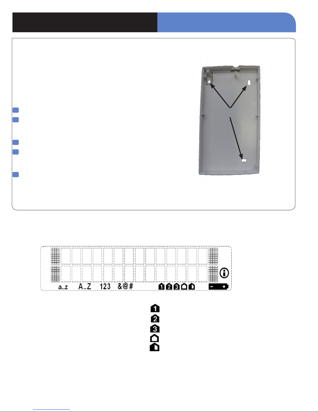
2
Hold base against mounting surface and mark the three
mounting holes. Use the left or right side to level the
keypad.
3
Drill pilot holes and install anchors where needed.
4
Place base on mounting surface so holes line up with
pilot holes/anchors and secure base with appropriate
screws.
INSTALLATION DATA SHEET
Mounting Holes
5
Attach Keypad to base and secure by turning the button to
the closed padlock symbol.
Note: The XMA Keypad is a supervised device and must be
permanently mounted. This product is not intended
for portable use.
2. LCD Overview
Icons for entry mode:
a..z Lowercase
A..Z Uppercase
123 Keypad
&@# Symbols
Information Icon
Low Battery Icon
Icons for arming mode:
Partition 1 or SP1 selected
Partition 2 or SP2 selected
Unused
External arming mode selected
Unused
www.videofied.com
 Loading...