

Videofied XL200L, XL600L, XL700L, XL GPRS Installation Manual
XL200L / XL600L / XL700L GPRS Control Panel
INSTALLATION MANUAL
Doc. - Ref. 230 -XLL
Last modification date : June 2014
Firmware version : XLP.04.04.05.X XX and later
www.videofied.com

Introduction
Description
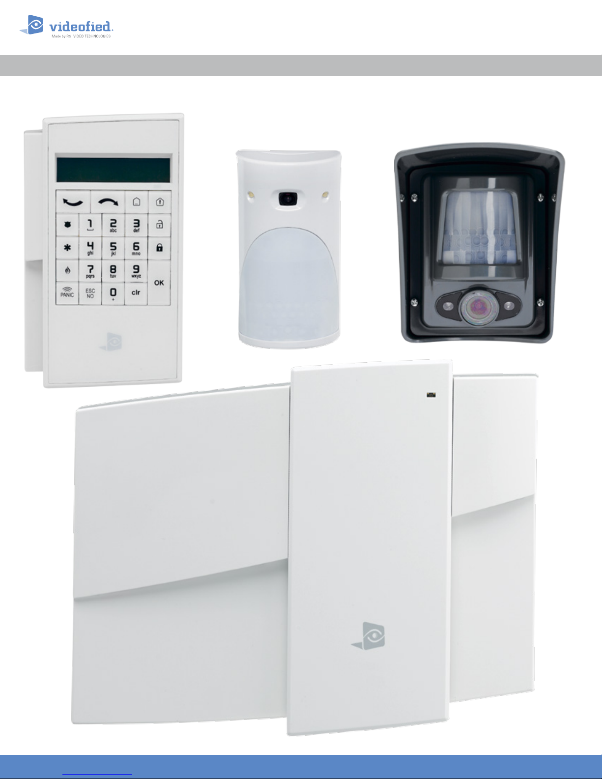
The XLL control panel is a Videofied wireless alarm system operated by battery or mains power supply. This
panel is intended mainly f or residential and commercial markets. With the Motion Viewers™ and Videofied®
range of products, the XLL panel provides video verification in case of intrusion.
The XLL panel is a standalone alarm system with an integrated GPRS / GSM communicator for connection to
a central station.
Wireless Technology
The XLL GPRS, along with all Videofied devices, uses the patented S2View®, Interactive, AES Encrypted
Wireless technology, providing optimum signal integrity and security.
The bi-directional RF communication path between all devices and the system control panel guarantees high
signal reliability. Integrated antennas eliminate protruding wires or rods, both more difficult to install and
unsightly to consumers, and potentially troublesome if damaged.
The panel supervises every device (excluding the remote key fob) to validate current open/close state,
tamper condition, serial number, date of manufacture, firmware revision, and battery status.
INSTALLATION MANUAL
The RSI VIDEO TECHNOLOGIES team wishes you a good installation.
Locking Screw
Integrated Siren
Status LED
Programming Button
www.videofied.com
2

Summary
INSTALLATION MANUAL
Introduction....................................................................................................2
Summary..........................................................................................................3
1. XLL Panel Setup.................................................................................................4
1.1 XLL Panel Setup...............................................................................................................4
1.2 SIM Card Installation
1.3 XLL Assembly
1.4 Powering and Initialization
1.5 Pairing the Remote Keypad..............................................................................................5
...................................................................................................4
..........................................................................................4
...................................................................................5
2. XLL Panel Programming......................................................................................6
3. XLL Features Guide............................................................................................13
3.1 Get to Access level 4...................................................................................................13
3.2 How to Arm/Disarm the System.....................................................................................13
3.3 Arming and Siren Mode Configuration...........................................................................14
3.4 Manage badges and access codes...................................................................................15
3.5 Delete the keypad or any other device..........................................................................17
3.6 Read the events log.........................................................................................................18
3.7 Opening the cover of an installed panel..............................................................................18
3.8 Golden rules......................................................................................................................18
4. Transmitted Events List......................................................................................19
5. 2G3G Error Codes............................................................................................20
6. Technical Specifications and Security Notes........................................................21
www.videofied.com
3
1. XLL Panel Setup
1.1 XLL Panel Setup
Open the box and remove the cardboard
mounting template sit ting on top. Place the
template on wall with the arrow pointing upward.
Mark the 5 screw points on the wall and drill pilot
holes for wall anchors. Install wall anchors, then
attach base of control panel to wall.
XLL panel is provided with a reinforcement brace
kit including 4 velco straps. Inser t the 4 straps in
the back casing, then mount the casing on the
wall. (The EN50131 standard requires the installation
of this brace kit).
A screw must be used in the tamper protection
hole for the panel wall tamper to function
correctly.
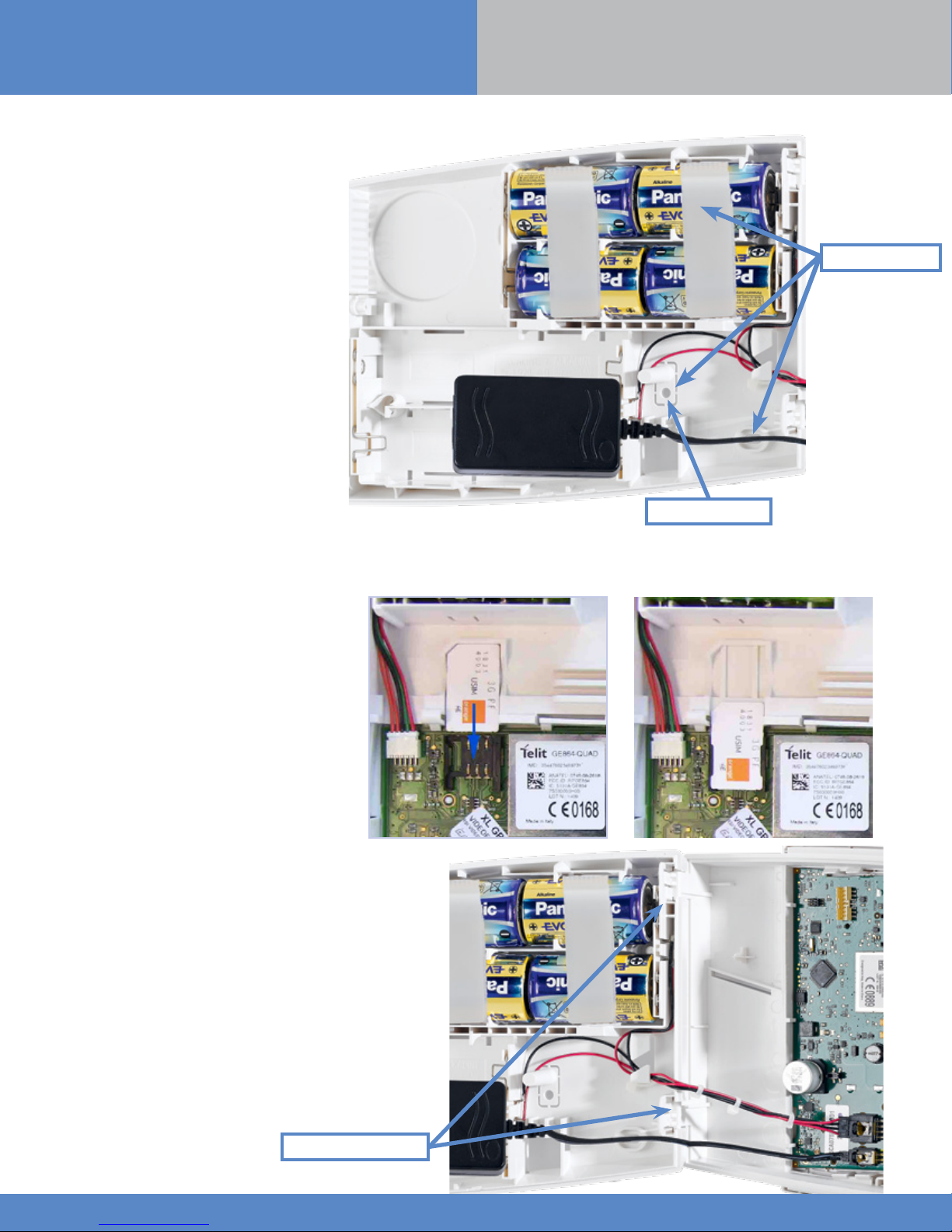
Insert the Alkaline D type batteries as shown;
ensuring the polarity matches the labeling on the
inside of the battery cover.
INSTALLATION MANUAL
Bracket holes
1.2 SIM Card Installation
Before removing the front cover from its box,
Put the SIM card on the plastic base (Take care
to respect the right direction).
DO NOT insert or remove the SIM card while the
panel is powered.
1.3 XLL Assembly
Tamper bracket hole
Mandatory to trigger tamper alarm.
Connect the panel’s face to its base by carefully
placing the hinges on it.
2 locking clips are provided to strengthen
the hinges: position each locking clip before
locking them completely (The EN50131 standard
requires the installation of these locking clips).
Locking clips location
www.videofied.com
4
1. XLL Panel Setup
INSTALLATION MANUAL
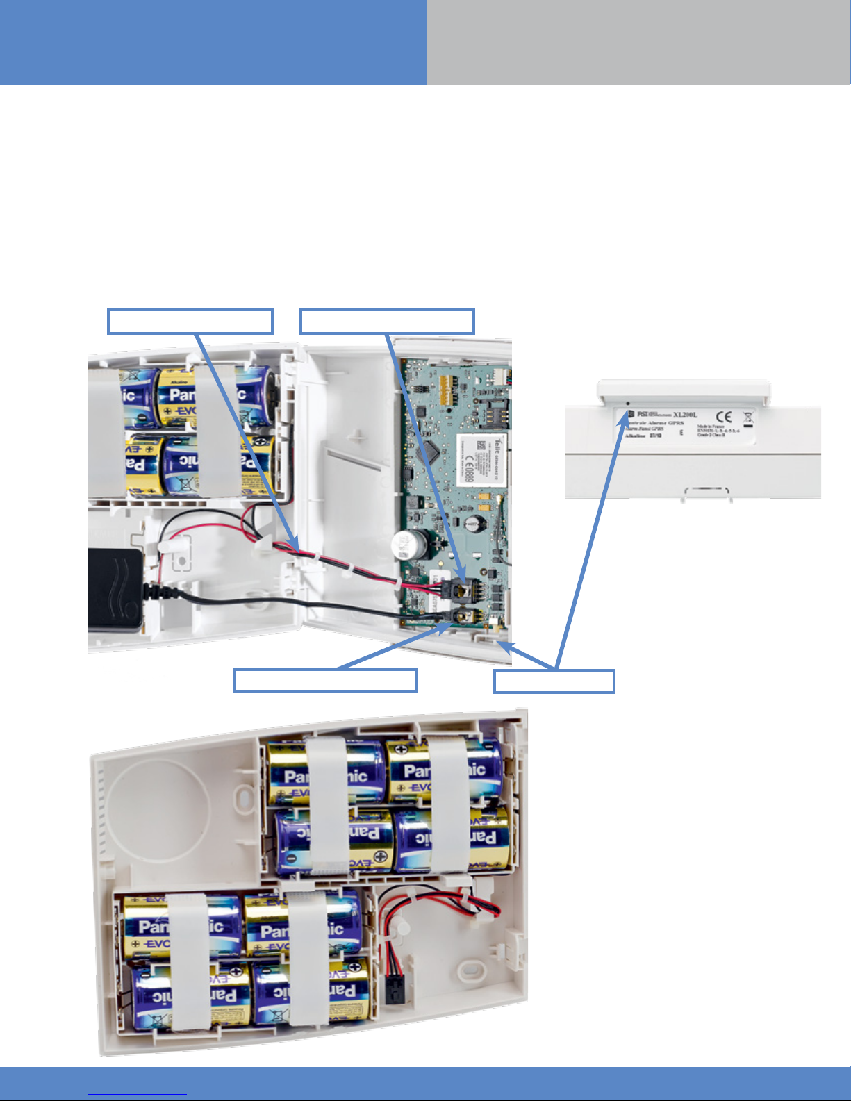
1.4 Powering and Initialization
• The panel is powered either with a mains power supply with 4 backup LR20 Alkaline batteries (Option 1 recommended) or with 4
LSH20 Lithium batteries (Option 2).
• Press and hold the PROGRAMMING BUTTON for 10 seconds, until the indicator LED blinks twice.
• The panel is now reset, a CMA, XMA or XMB has to be enrolled to configure the panel.
THE CONTROL PANEL MUST BE CONNECTED TO AN EXTERNAL POWER SUPPLY (OPTION 1)
WHEN USING THE RINGTONE FEATURE OR SMARTPHONE APP.
Batteries cable Batteries connector
Option 1
Option 2
Mains Connector
Programming button
To install the power supply inside
the box,
battery separator.
break the plastic
www.videofied.com
5

1. XLL Panel Setup
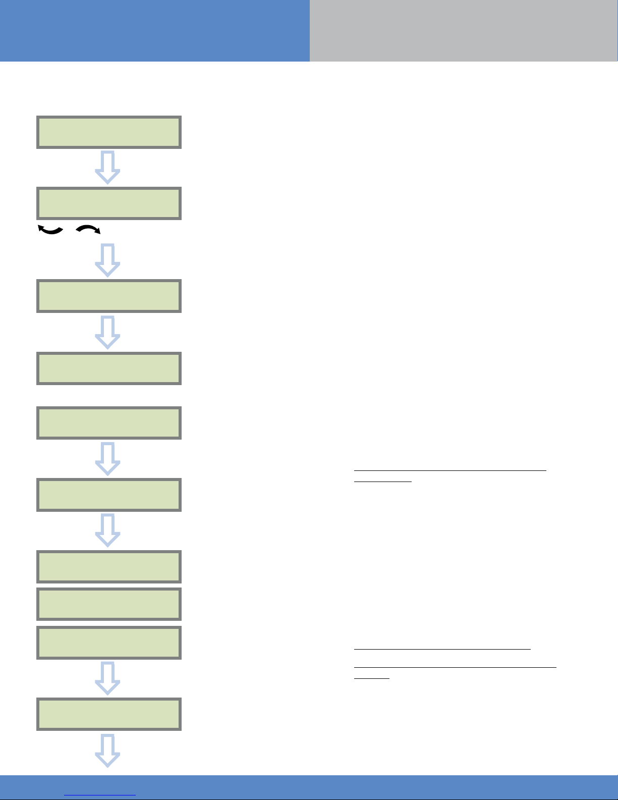
1.5 Pairing the Remote Keypad
• Press the XLL programming button and release for the
enrollment of a programming keypad.
• Insert all LS14500 Lithium batteries into the keypad.
• Do not mount the keypad. It will display one of the
following screens:
INSTALLATION MANUAL
RSI (c) 2013
videoed.com
• Press on both
and release. The indicator LED on the keypad will blink
rapidly. Wait for the keypad to pair.
• If the keypad doesn’t pair up with the panel and
shows «XX», it certainly means that it is still paired to
another system and needs to be reset. Take the batteries
out, and press repeatedly on the keypad tamper switch.
Then proceed to the above steps.
CLR
and
<=========XX=========>
or
ESC NO
keys at the same time
www.videofied.com
6
2. XLL Panel Programming
INSTALLATION MANUAL
Keypad Display Actions and comments
KE YPAD 1
RECORDED
OK or YES
The system can also be programmed in: french, italian,
< - LANGUAGE : - >
ENGLISH (UK)
for language selection
OK or YES
RADIO RANGE TEST?
german, dutch, spanish, swedish, portuguese, danish,
czech and polish.
The language can be changed at any time once the panel
is programmed in the MAINTENANCE menu.
OK or YES
RF TEST
x/9
Please wait
RF TEST
9/9
OK or YES
RADIO RANGE TEST?
ESC
NO
INSTA L L ER CODE
4 TO 6 DIGITS
THEN OK/YES
INSTALLER CODE :
The Radio Range test must be run during the device
learning process in order to ensure proper pairing with
the control panel. This test measures the strength of
communication between the device and the control
panel. The keypad will display a real time radio range
value on a scale of 9.
To receive the most accurate results you must run the
radio range test for at least 30 seconds.
Result must be 8 out of 9 or better for reliable
transmission.
Using the Alphanumeric Keypad, enter the Installer Code
of your choice.
The Installer Code will be used for all future maintenance
and configuration.
This code is important to keep track of.
OK or YES
CONFIRM CODE
OK or YES
There is no back door or Default codes to the
system.
Please refer to the restriction rule for codes (Chapter 3.4).
Some codes are already used by default and therefore
cannot be used.
www.videofied.com
7
 Loading...