

Videofied W730, WIP720, WIP730 User Manual
W & WIP ALARM PANEL
INSTALLATION MANUAL
DOC. - REF. 230-W-WIP-AUS
LAST MODIFICATION DATE : NOVEMBER 2016
FIRMWARE VERSION : XLP.07.07.15.XXX AND LATER
1

2
W & WIP Alarm panel
Description
Since 2002, RSI VIDEO TECHNOLOGIES provides the only wireless video verification on the market,
thanks to the Motion Viewer™ detectors and to the Videofied
®
product range.
After 2 years of development, RSI VIDEO TECHNOLOGIES is proud to present the new W alarm panel.
The W alarm panel is wireless and mains powered with a backup rechargeable battery (provided).
The W panel is the first Videofied
®
alarm panel that can be used as a connected device.
This panel is intended for residential and commercial markets.
Like all the Videofied
®
alarm panels, the W panel is compatible with every radio device manufactured
by RSI VIDEO TECHNOLOGIES.
Technology
The W alarm panel uses the S2View
®
patented technology. That interactive and wireless technology
ensures signal integrity. The bidirectional radio link maximizes the signal reliability.
AES encryption protects the communication between the panel and the devices. Transmission security
is optimal.
The jamming detection feature identifies any intentional jamming from a third party.
The supervision feature consists of transmitting signals between every device of the system and the W alarm
panel. Through the supervision, the detectors transmit every 8 minutes a presence signal.
The entire RSI VIDEO TECHNOLOGIES team wishes you a successful installation.
INTRODUCTION

3
W & WIP Alarm panel
Introduction................................................................................................2
Summary.........................................................................................................................3
1. W installation and setup.......................................................................................................4
1.1 Panel overview..........................................................................................................................................4
1.2 Panel mounting..........................................................................................................................................4
1.3 Ethernet cable connexion........................................................................................................................5
1.4 SIM card installation................................................................................................................................5
1.5 Powering and initialization......................................................................................................................5
1.6 Indicator lights...........................................................................................................................................6
1.7 Pairing the keypad..................................................................................................................................6
2. W panel programming.............................................................................................................................7
3. W panel features guide..........
..............................................................................................................17
3.1 Get to access level 4........................................................................................................................17
3.2 How to arm/disarm the system...........................................................................................................17
3.3 Arming and siren mode configuration...............................................................................................18
3.4 Manage badges and access codes.....................................................................................................19
3.5 Delete a device from the system........................................................................................................21
3.6 Read the event log...............................................................................................................................22
3.7 Automatic arming/disarming...................................................................................................................22
3.8 Golden rules.............................................................................................................................................22
3.9 Additional features..................................................................................................................................23
4. Ethernet parameters...............................................................................................................24
5. Transmitter events list...........................................................................................................25
6. 2G3G error codes..................................................................................................................26
7. Security and certifications notes..........................................................................................27
8. Technical specifications..........................................................................................................29
SUMMARY

4
1. W INSTALLATION AND SETUP
INSTALLATION MANUAL
W & WIP Alarm panel
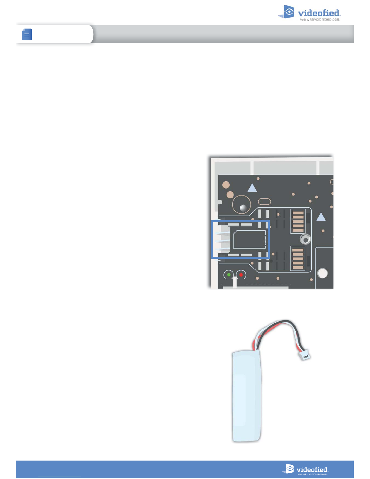
1.1 Panel overview
SIM card installation
Ethernet cable
connection
Status LEDs
Mini-USB connector
for power supply
Battery connector
1.2 Panel mounting
Fix the back casing on the
wall using the three mounting
holes (4 mm diameter) as
shown.
Mounting the panel is not
required for programming.
Bracket holes
COM button INIT button Locking screws
WIS100
Siren connector
5
1. W INSTALLATION AND SETUP
INSTALLATION MANUAL
W & WIP Alarm panel
1.4 SIM Card Installation
Insert a Mini-SIM 2FF SIM card in the location shown in the image.
Please refer to the markings for the insertion direction.
Use a M2M (machine-to-machine) 2G3G SIM card. If the panel is
used with a smartphone application, the SIM card shall be able to
receive SMS.
DO NOT insert or remove the SIM card while the panel is powered.
1.3 Ethernet cable connection
Once the panel is fixed on the wall connect a RJ45 cable between the site internet network and the panel Ethernet port.
When the panel attempts a transmission via Ethernet, a red LED on the connector will flash. This will allow the installer to
check whether the panel is connected to a valid network.
Do not touch the RJ45 cable when the panel is powered.
IMPORTANT :
Only connect the panel on 10Base-T SELV networks.
Only for WIP 720/730 models
1.5 Powering and initialization
AC Power
• Connect the backup battery.
• Install the power supply inside or outside the panel box
depending on the needed cable length.
• Connect the power supply to the panel mini-USB connector.
• Plug the power supply in an electrical outlet.
• Do not connect the 12V input (sealed by a label), specifically when
the panel is powered.
Initialization
• Leave the panel open. The green status LED is on. Press and hold
the INIT button for 6-7 seconds until the status LED turns red for 1
second.
• The red LED blinks several times then turns off. That procedure
resets the panel memory.
• The panel is now reset, a Videofied
®
keypad has to be enrolled to
configure the panel.
Backup battery

6
1. W INSTALLATION AND SETUP
INSTALLATION MANUAL
W & WIP Alarm panel
1.6 Indicator lights
Red LED on
Red LED blinking
(1 sec)
Red LED blinking
(3 sec)
Red LED off
Green LED on
(AC power detected)
N/A
Battery out of order
or not detected.
Low voltage on
the battery.
Normal
operation
Green LED off
(AC power not detec ted)
Low voltage on the
battery
N/A
Panel working on
battery. Battery OK.
Panel not powered
or out of order.
1.7 Pairing the remote keypad
• Press briefly the panel INIT button and release for the enrollment of a programming keypad.
• Insert 3 or 4 LS14500 Lithium batteries into the keypad.
• Do not mount the keypad. It will display on of the following screens:
RSI (c) 2014
videofied.com
<=========XX=========>
or
• Press on both
CLR
and
ESC NO
keys at the same time and release. The indicator LED on the keypad will blink rapidly. Wait
for the keypad to pair.
• If the keypad does not pair up with the panel and shows “XX”, it certainly means that it is stilled paired to another
system. The keypad needs to be reset. Remove the batteries and press repeatedly on the keypad tamper switch for 30
seconds to 1 minute. Then proceed to the above steps.
7
2. W PANEL PROGRAMMING
INSTALLATION MANUAL
W & WIP Alarm panel
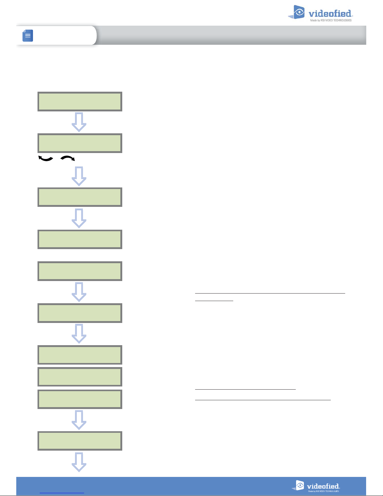
Use the keypad to program the panel
Keypad Display Actions and comments
KEYPAD 1
RECORDED
RAD IO RANGE TE ST?
RF TEST
x/9
RF TEST
9/9
RAD IO RANGE TE ST?
INST ALL ER CODE
4 TO 6 DIGITS THEN OK/YES
INST ALL ER CODE :
< - LANGUAGE : - >
ENGLISH (UK)
The system can also be programmed in : french, italian, german,
dutch, spanish, swedish, portuguese, danish, czech, turkish and
polish.
The language can be changed at any time once the panel is
programmed in the MAINTENANCE menu.
The radio range test must be run during the device learning
process in order to ensure proper pairing with the control
panel.
This test is important, it measures the strength of
communication between the device and the control panel.
The keypad will display a real time radio range value on a
scale of 9.
To receive the most accurate results you must run the radio
range test for at least 30 seconds.
Result must be 8 out of 9 or better for reliable
transmission.
OK or YES
OK or YES
Attendre
OK or YES
ESC
NO
for language selection
OK or YES
CONFIRM CODE
OK or YES
OK or YES
Using the alphanumeric keypad, enter the installer code of your
choice.
The installer code will be used for all future maintenance and
configuration.
This code is important to keep track of.
There is no back door or Default codes to the system.
Please refer to the restriction rules for codes (Chapter 3.4).
Some codes are already used by default and therefore cannot
be used.
8
2. W PANEL PROGRAMMING
INSTALLATION MANUAL
W & WIP Alarm panel
You may name the installer code using the alphanumeric
keypad.
If using automatic setting (called installer default list),
enter the name of the list.
Warning : If the wrong installer list name is used, it
cannot be set later, the system must be defaulted.
Leaving the name blank by pressing
ESC NO
, it will be
named ‘ACCESS 1’ by default.
CODE NAME :
OK or YES
ACCESS 1
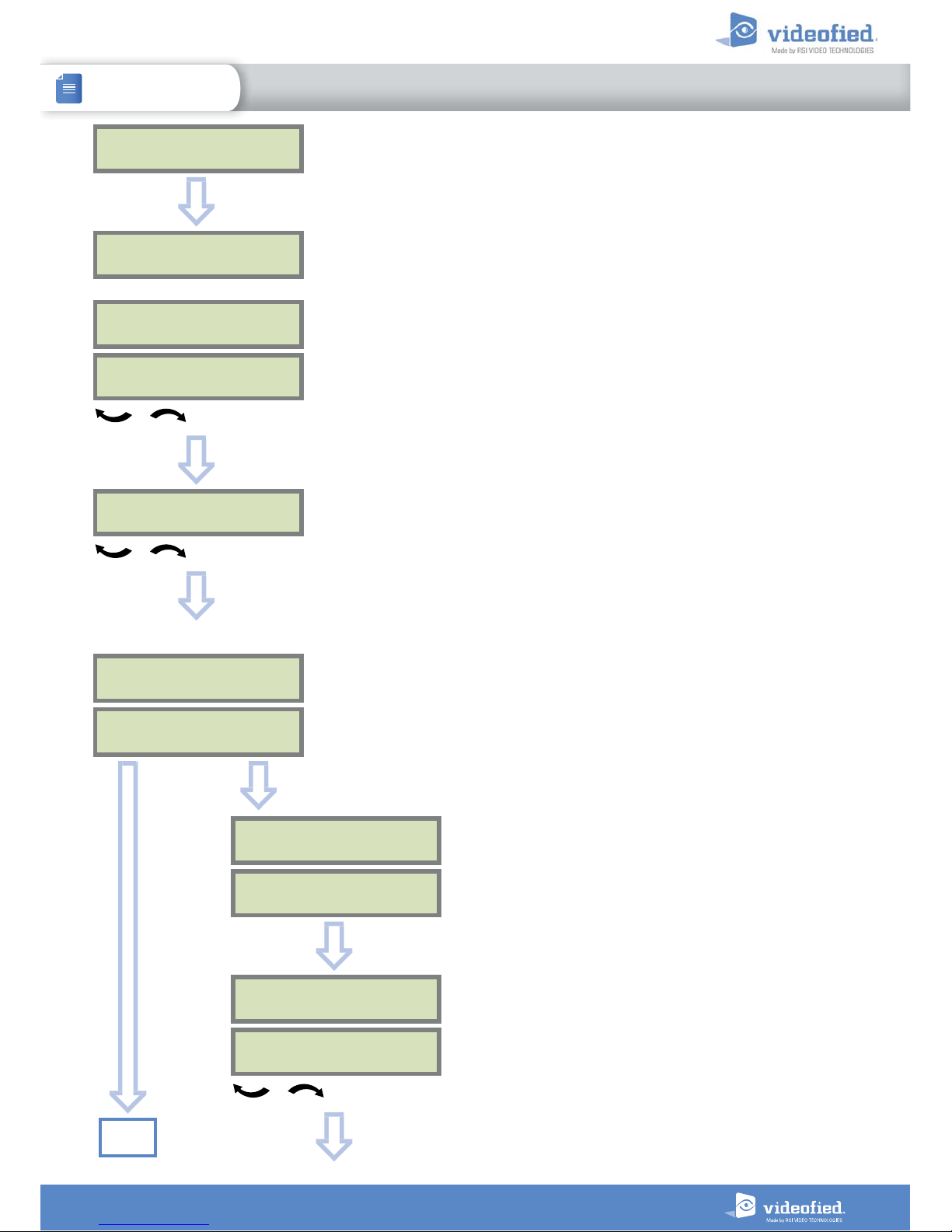
REGISTERED
Wait
ADJUSTING
DATE AND TIME
DATE (YEAR):
15/ /
To set the year
OK or YES
DATE (MONTH):
15/01/
To set the month
OK or YES
You may proceed in the same way for :
Day, Hour and Minutes
15/01/19 10:47
ENTRY COMPLETE !
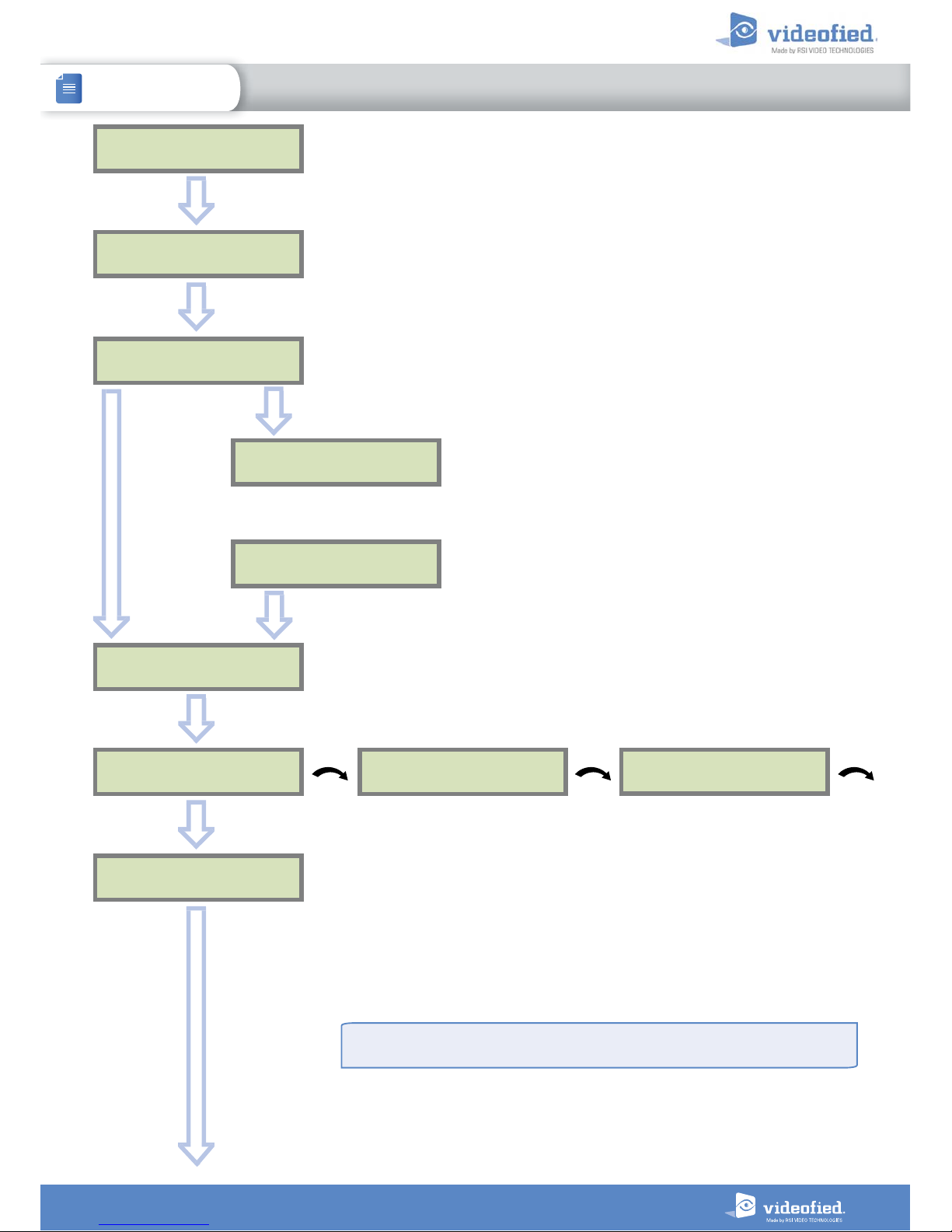
CONNECTED TO
MONITOR. S TATION?
OK or YES
Use the alphanumeric keypad to enter in a 4-8 digit account
number provided by the Central Station
ACCOUNT NUMBER :
ACCOUNT NUMBER :
567001
OK or YES
PERIODIC TEST
PERIO DI C TEST :
24 HOURS
To select periodicity
OK or YES
Test Periodicity: 1 hour, 12 hours, 24 hours, 48 hours, 7 days
or no tests.
We suggest a 24 hours periodic test call.
ESC
NO
Go to
page 10
9
2. W PANEL PROGRAMMING
INSTALLATION MANUAL
W & WIP Alarm panel
TEST (hour ) :
04:
CODE / TEST
MODIFICATION ?
OK or YES
TEST ( min ut es) :
04:15
OK or YES
OK or YES
The CODE/STATE MODIF. menu is used to configure the
transmitted events to the monitoring station. Use the arrow
keys to toggle between events and
OK or YES
to modify.
ALARM: event transmitted upon occurrence.
ALARM/END: event is transmitted on occurrence and on
event restoral.
NOT TRANSMITTED: event is not transmitted, however it
will appear on the keypad.
Please liaise with your Monitoring Station to ensure
that the requested events to transmit are correctly set.
CODE / TEST
MODIFICATION
Events list
ESC
NO
SERVER
ADRESSE S ?
OK or YES
Wait
SERVER
ADRESSE S ?
IP1 ADDRESS
0.0.0.0
DOMAIN NAME 1
PORT 1
888
The IP1 address, Domain Name 1 and/or Port 1 are provided by the monitoring
station.
Leave Port details at 888 unless otherwise instructed.
Press
OK or YES
to enter/modify the parameter then
OK or YES
for validation.
WARNING : You will use either an IP address or a Domain name, but not both, leave
the Domain name blank if an IP address has already been entered.
Press on the right arrow to configure IP/Domain name 2 and PORT2 (for the back-up
server), and IP/Domain name TMT and PORT TMT (to configure remote maintenance
server).
ESC
NO
ESC
NO
ESC
NO
The panel transmits in priority to IP1 (or DOMAIN NAME 1) / PORT 1 then to IP2 (or
DOMAIN NAME 2) / PORT 2 as a backup.
 Loading...