

Videofied VISIO, V6000, V7000, VISIO1000 Installation Manual
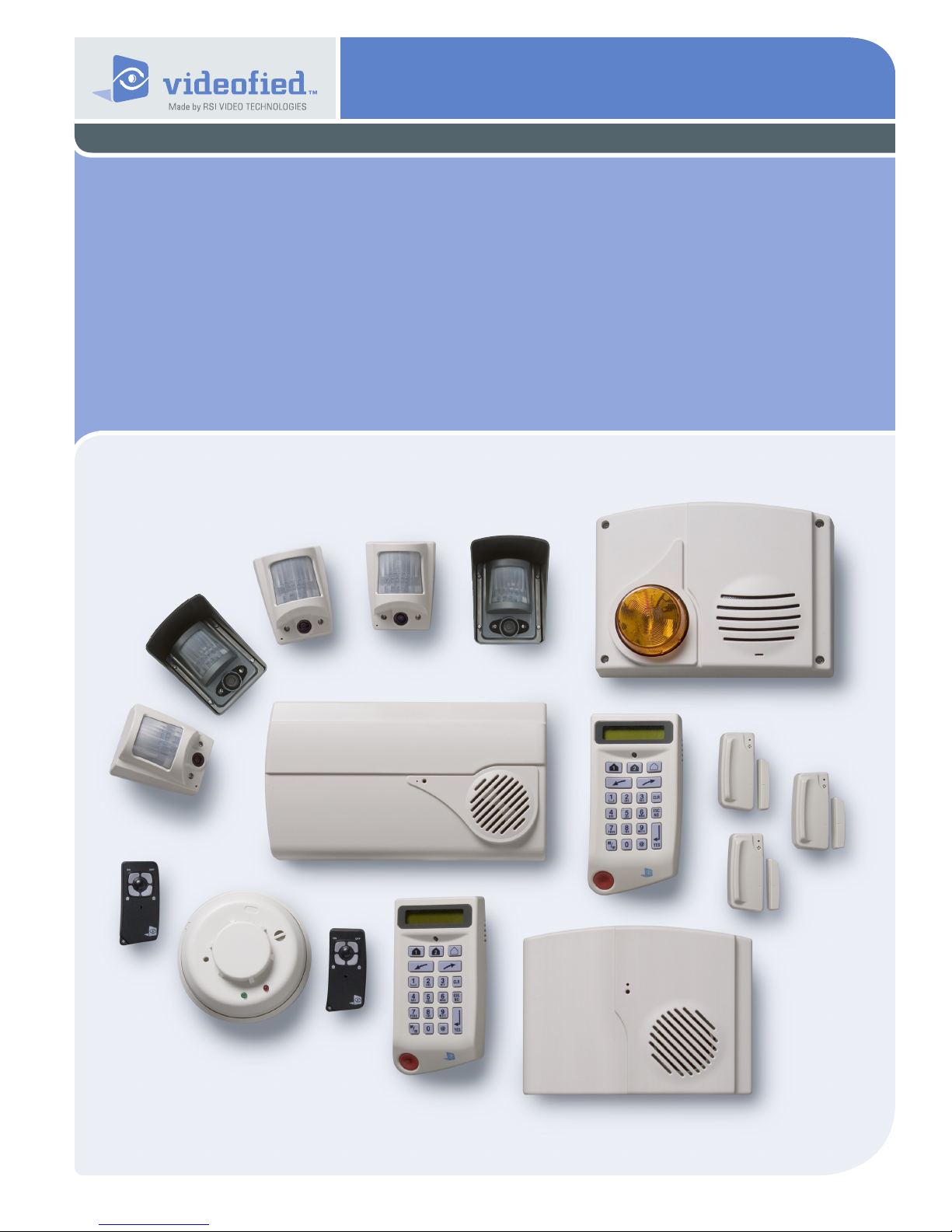
Security System Videofied
Made by RSI VIDEO TECHNOLOGIES Document No. 2100-V July 2009
Installation
Manual
A panel connected to the monitor station by a telephone line
Surtec / Surtec + Video protocol (with and without interphone)
®
- VISIO
Contact ID / Contact ID + Video protocol
VISIO means V6000 for USA/Canada, V7000 for Australia/
Singapore and VISIO1000 for Europe and rest of the world.
EMEA Hotline: +33 (0)820 846 620 / UK : 0871 951
EMEA Hotline: 877-206-5800

Contents
1. Preparation before programming ............................................ 1
2. The golden rules .................................................................... 1
3. Installation and programming ................................................ 2
3.1 Initialize the panel .......................................................................2
3.2 Record the keypad ....................................................................2
4. End of installation .................................................................... 6
5. How to .....................................................................................6
5.1 Return back to the inactive state of the keypad .......................6
5.2 Change to installer level ...........................................................6
5.3 Add a user code ........................................................................6
5.4 Modify the level of a user code.................................................6
5.5 Program the arming modes prole ...........................................6
5.6 Set the interphone to 180 seconds ..........................................7
5.7 Disactivate the panic button of the keypad ..............................7
5.8 Add a telephone prex .............................................................7
5.9 Reintegrate the panel siren .....................................................7
5.10 Delete the tempo bips report of the sirens .............................7
5.11 Reinitialize a panel ...................................................................7
5.12 Add a device after an initial conguration .............................7
5.13 How do you activate/disactivate the monitor station? ............8
6. Detail of the menu : alarm codes ...........................................8
6.1 Signalling events by default ......................................................8
6.2 Alarm code, default codes .......................................................9
For further information, consult the installation manual :
- Installation data sheet “Keypad"
- Installation data sheet “Indoor MotionViewerTM”
- Installation data sheet “Outdoor MotionViewerTM”
- Installation data sheet “Motion detector”
- Installation data sheet “Indoor siren”
- Installation data sheet “Outdoor siren”
- Installation data sheet “Remote control"
- Installation data sheet “Silent Panic Keyfob”
- Installation data sheet “Proximity Reader"
- Installation data sheet “Motion detector”
- Installation data sheet “Control relay”
- Installation data sheet “Synoptics of the menus”
- Installation data sheet “GPRS - Version 32 Panel"
- Installation data sheet “GPRS - Previous Version 32 Panel”
- Installation data sheet “XTENDER"
- Installation data sheet "New functionalities”
Regulatory Information for USA
FCC Par t 15 Information to the User Changes or mod ications no t expr essly
approved by RSIalarm, Inc. can void the user’s authorit y to operate the equipment.
FCC Part 15 Clas s B This equipment has been tested and found to comply with the
limits for a Class B digital devic e, pursuant to par t 15 of the FCC Rules. These limits
are design ed to pr ovide reason able protection against interference in a residential
installation. This equipment generates, uses, and can radiate radio frequency
energy and, if n ot installed and used in accordan ce with the instructions, may cause
harmful interference to radio communications. However, there is no guarante e that
interference will not occur in a parti cular inst allation.
If this equipment does cause harmful interfer ence to radio or television reception,
which can be determined by tur ning the equipment off and on, the use r is encouraged
to try to c orrect the interference by one or more of th e followin g measures:
• Reorient or reloc ate the rec eiving ante nna.
• Incr ease the separation b etween th e equipment and the receiver.
• Connect the affe cted equipment and the panel rece iver to separate AC power
outlets, on diffe rent branc h circuit s.
• Consul t the dealer or an experi enced radio/T V technici an for help.
ACTA Part 68 This equipment complies with Part 68 of the FCC Rules and the
requirements adopted by the ACTA. Located on this equipment is a label that contains,
among other inform ation, the registrat ion number and the ringe r equivalence number
(REN) for this equipment. If requested, this informati on must be provided to
the telephone com pany. The REN for t he panel is 3.6”.
Docum ent No. US:
The REN is used to de termine the maximum number of device s that may be connected
to your tel ephone lin e. Excess ive RENs on a te lephone line may result in devices n ot
ringin g in response to an incoming call. In most areas, th e sum of all device RENs
should not exceed ve (5.0). To be c ertain of the number of device s that may be
connected to a l ine, as determin ed by the total RENs, contact the local telephone
company. For product s approved after July 23, 2001, the REN for this product is
part of the produc t identi er that has the format US:AA AEQ# #TXX XX. The digits
repres ented by # # are the REN with out a decimal point (e.g. 02 is a R EN of 0.2). For
earlier product s, the REN is separately shown on the label.
A plug and a jack used to connect this equipment to the pr emises wiring
and telephon e network must comply with the applicabl e FCC Part 68 Rules and
requirements as adopted by ACTA. A compliant tel ephone cord and modul ar plug is
provided with this produc t. It is designed to be connected to a compliant mod ular jack.
See the In stallati on Manual for details.
Alarm dialing equipme nt must be able to seize the telephone l ine and place a call in
an emerge ncy situati on. It must be able to do this even if other equipment (teleph one,
answering machine, computer modem, etc.) alrea dy has the telephone line in use. To
do so, alarm dialing equipment m ust be connected to a properly i nstalled RJ31X jack
that is electrically in seri es and a head of all other equipme nt connected to the same
telephone line. Proper inst allation is depicted in the following diagram. If you have any
questions con cerning these instruc tions, consult with your local teleph one company
or a qualied instal ler abo ut installing a RJ31X jac k and a larm di aling eq uipment for
you.
If this equipment causes harm to the telephone network, the telephone comp any may
temporarily disconnect your service. If possible, you will be notied in advance. When
advance notice is not practic al, you will b e notied a s soon as pos sible.
The telephone company may make change s in it s facilities, equipment,
operat ions, or proce dures that could affe ct the operation of t he equipment.
The te lephone company may ask you to dis connect the equipment from
the network until the problem has been cor rected, or you are sur e that th e
equipment is not malf unctioning.
This equipment may not be used on coin servic e provided by the telephone com pany.
Connection to par ty lines is subject to state tariffs.
This device compli es wit h Par t 15 of the FCC Rules. Operation is subjec t to th e
following two condit ions: (1) this device may n ot causeharmful inter ference, and (2)
this device must accept any interferencerec eived, including inter ference that may
cause un desired operation.
RF Exposure Warning: During o peratio n, t he user has to keep a minimum
separation dista nce of 20 cm with the RF devices.
For Canada:
This material complies with the applicable technical specications
of Canadian industries.
The use of this device is only authorized in the following conditions :
(1) It must not produce jamming and (2) the user of the device must be prepared
to accept every wireless jamming recieved, even if it is a sensitive jamming
that may affect the functioning of the device.
The Ringer Equivalent Number is an indication of the maximum number of devices
allowed to be connected to a telephone inter face. The termination on an interface may
constist of any combination of devices subject only to the requirement that the sum of all
the RENs of all the devices does not exceed 5.
1. Preparation before programming
On a piece of paper :
• Name the 4 geographical zones
A geographical zone corresponds to a surface where all the
sensors are armed/disarmed together.
These 4 geographical zones are going to help in the creation of
partial arming proles. A partial arming prole is a combination
of geographical zones which are either armed or not. By
using the examples below, you are going to meet most of the
requirements.
Area
1 ENTRY DELAY 1 ENTRY DELAY
2 MAGAZINE 2 RDC
3 STOCK 3 FLOOR or OFFICE
4 DISCOUNT 4 GARAGE
A magazine Area A person
(The1st geographical zone is inevitably delayed)
• Name the devices
Be as explicite as possible because in case of intrusion, it is this
device's name that will display on the keypad and transmit to the
monitoring station. Example : CAM HALL ENTRANCE (for a
camera at the entrance).
• Dene the partial arming proles (combinations of
areas, see paragraph 5 and the partial programs on page 6).
• Ask the end user to prepare his/her codes (19
maximum access codes with 4 to 6 numbers per code).
• Allocate a geographical zone (from 1 to 4) to each
device.
2. The golden rules
1 7
Any device in the same area as the keypad or proximity
reader will be subject to Entry and Exit delays.
Never place the panel near an electric switchboard :
2
there is possible interference with the radio and GPRS
modem.
3
Place the alarm panel at the most central location of the
site to be protected (also garantees a better propagation of
the radio).
When there is typing error, use the to delete the
4
incorrect character.
5
Never record the same device twice without
having rst deleted the device off of the panel.
6
Record a maximum of 25 devices of any kinds, without
distinction (initial keypad included). You are limited to 3
Keypads or Badge readers or combination there-of.
Respect the installation height (under device) of
PIR : 2m10 to 2m30, cameras MotionViewerTM : 2m10 to
2m30 (ideally in an unobstructed angle), MotionViewerTM
pet immune : 2m10.
Never permanently mount the keypad at the
8
begining of installation, so that you can walk around with it
during programming.
9
Always clean the camera's lens after installation
(with a clean and dry piece of cloth, without pressing
on the lens).
To change from Capital to lower case, rst press the
10
key, then change from small letter/capital letter with
and vice-versa.
The keypad becomes inactive after 30 seconds of
11
inactivity, in order to make the display to reappear,
press on the [YES] key.
1
2. The golden rules
In the presence of ADSL in partial unbunding,
12
immperatively use a passive ADSL lterbefore
connecting the panel on the main telephone line.
13
The functioning in VoIP behind an ADSL “box” is not
guaranteed.
14
Only use SAFT LSH20 lithium batteries for
the control panel and the LR20 alcalines batteries for
the sirens interior, exterior and the RAR100 control relays.
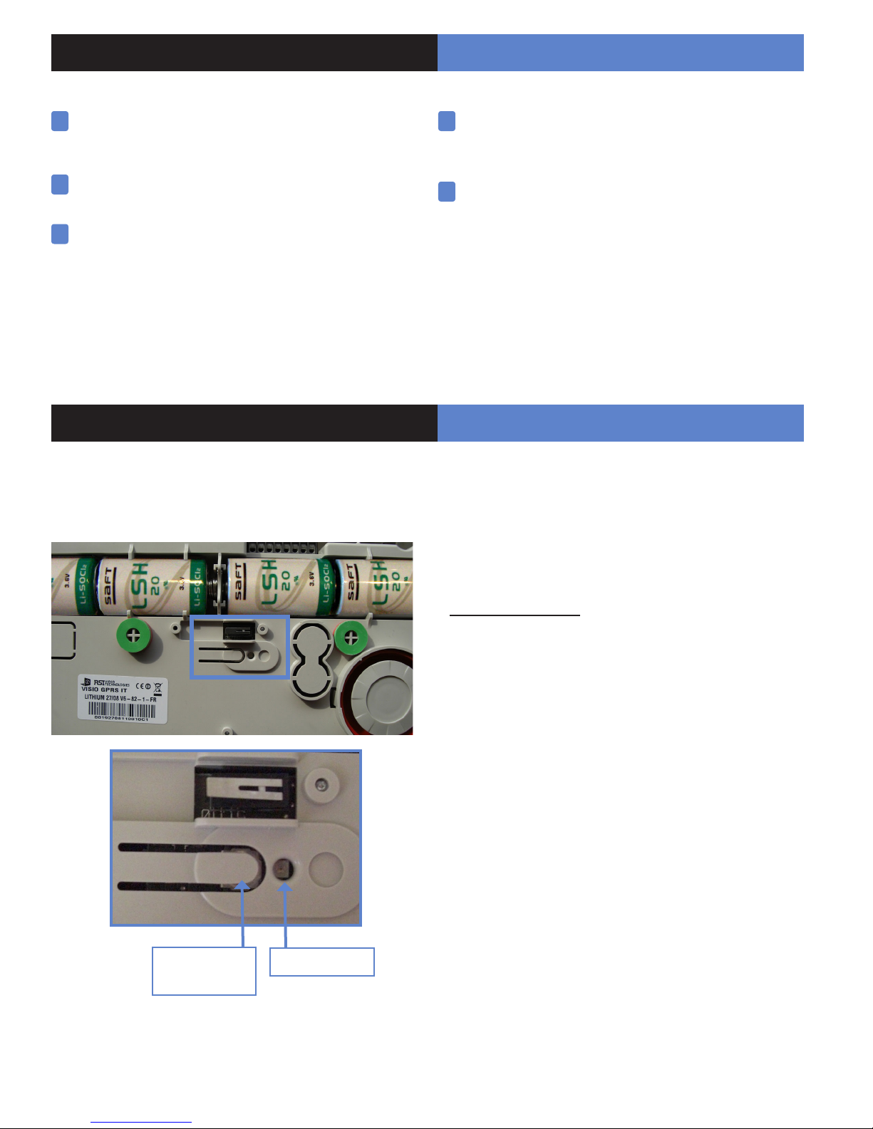
3. Installation and programming
Fix the panel on the wall and put the telephone cable in the
SIM card before putting in the batteries.
The ITRA110/600 and DCVA200/600/700 (devices
15
with pet immune) should never be placed
in stairs, or near stairs. (Risk of untimely triggerings).
Never change the name of the installer code, after
16
installation, it could (according to the panel version) come
back in level 3 and lock your system.
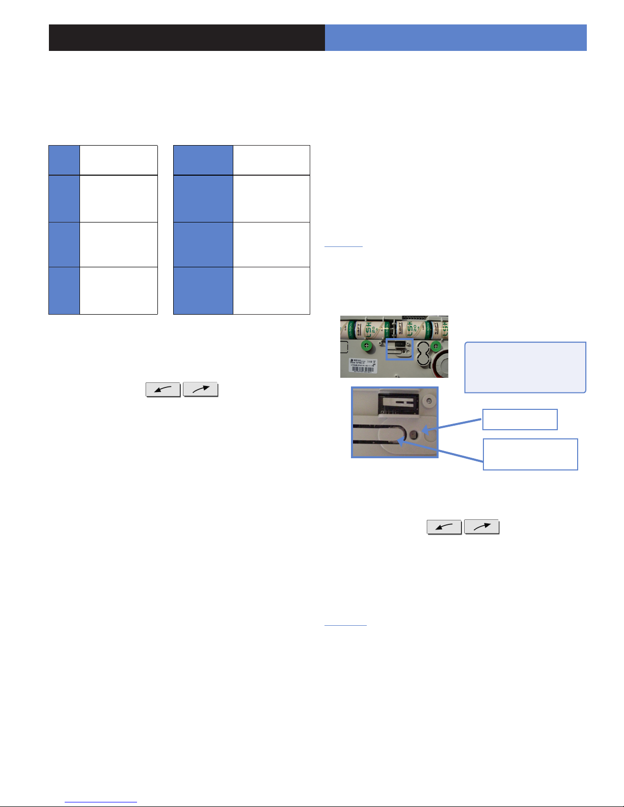
3.1 Initialize the panel
• Open panel cover, rst insert the SIM card and then 2 Lithium
LSH20 batteries wait for two ashes of the panel's indicator,
then insert the other two batteries.
Panel PROGRAM
BUTTON
• Press very carefully on the PROGRAM BUTTON of the
panel (approximately 8 seconds) until the indicator ashes 2
times then release.
• Press and release on the PROGRAM BUTTON of the panel
(for approximately 1 second), the indicator ashes 1 time. The
panel is now ready for initial conguration and the recording of
the keypad.
3.2 Record the keypad (cf. Keypad installation
manual)
• Insert the 3 Lithium LS14500 batteries in the keypad.
• Do not x the keypad, it will help you in the recording and
setting of the devices.
• simultaneously press on [CLR] and [ESC NO] buttons on
the keypad, until the keypad's indicator ashes and then release.
Indicator
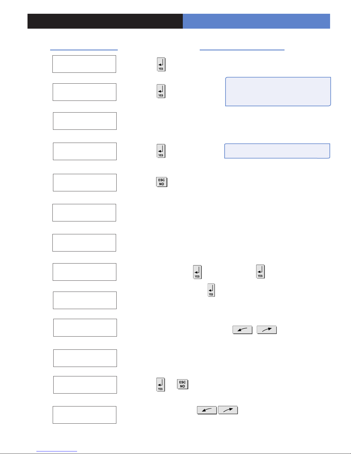
3. Installation and programming
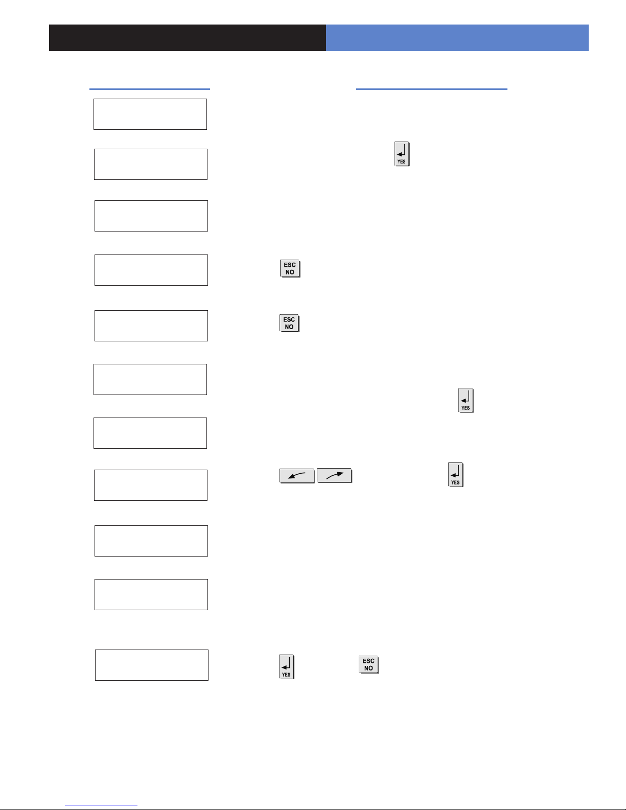
Display of the keypad
KEYPAD 1
RECORDED
RADIO RANGE
TEST ?
REQUEST IS SENT :
WAITTING ANSWER
TEST IN PROGRESS
END = YES
RADIO RANGE
TEST ?
ENTER THE
INSTALLER CODE
Wait
Wait
Actions and commentaries
Verify the range : A regular ashing or a
value of 2/5 or better indicates a sufcient
RF radio
In order to stop the test.
.
4 TO 6 DIGITS
THEN YES
INSTALLER CODE :
CODE NAME :
ADJUSTING
TIME AND DATE
DATE (Year) :
00/ /
CONNECTED TO
MONITOR STATION?
Wait
Installer code + then conrm : Code +
Naming the code + (Becareful, some NAMES correspond to pre-
programming of key accounts. (In case of incorrect setting, please contact
your technical department).
Wait
Use direction arrows right or left to increase the
numbers and the [YES] key to validate the value and move to the next.
Do the same for the Month, the Day, the Time and the Minutes.
(or if there is a vocal mode).
FORMAT :
(Format)
With the arrows select the desired protocol then
validate with the [YES] key.
3

3. Installation and programming
Keypad Programming
The choice of the protocol must be carried out according to the characteristics of the monitoring station PC. It
determines the protocol that has to be selected.
In general, in France with interphones, the protocole to be used could be:
SURTEC or (SURTEC + VIDEO in case of presence of cameras)
otherwise :
CONTACT ID or (CONTACT ID + VIDEO in case of presence of cameras) (North America only use Frontel)
Never select protocoles SURTEC + FRONTEL or CONTACT ID + FRONTEL
which are used for tests.
Display of the keypad Actions and commentaries
PHONE PREFIX :
ACCOUNT NUMBER:
TEL TELESURV 1 :
FRONTEL NBR 1:
PERIODIC TEST :
24 HOURS
TEST HOUR:
00
Enter prex if needed + , otherwise
* compose without tone. # does a 2 second break.
Enter the Transmetter code + , do not forget to add zeros in front if
need be (8 digits are necessary in SURTEC).
Enter the N° of telephone of he receptor SURTEC (or CONTACT ID) of he
monitoring station + (do the same for the TEL TELESURV 2).
If the SURTEC+VIDEO or CONTACT ID+VIDEO protocols have been
chosen then N° of telephone of the receptor VIDEO (FRONTEL) of the
monitoring station + . do the same for the PHONE NUMBER 2).
Then enter IP addresses : IP1 : 10.0.0.16 and IP2 : 10.0.0.16
by typing : (10+YES) + (0+YES) + (0+YES) + (16+YES)
to change the period +
to increase hours + , and do the same for minutes.
CODE/STATE
MODIFICATION ?
BY-PASS
ENABLE ?
ENTER
YOUR I.D. :
PANEL PHONE NB :
or (to modify the transmission state of events, turn to pages
8 and 9).
(For the individual, for the professional behind a fax and if the line
serves as switchboard, e.g. barber shop).
Remark : the activation of the BY-PASS helps the remote arming of the
system, as well as remote maintenance connection.
Wait
Enter phone number + (The client's, informative and optional data only.
This is the number spelled in vocal mode by the panel).
3. Installation and programming
Display of the keypad Actions and commentaries
ENTER NAME OR
ADRESS THEN YES
NAME OR ADRESS
NAME OR ADRESS
ENTRY COMPLETE
SENDING ALARM
BY EMAIL ?
RESPONDING PARTY
LIST ?
AREA
CONFIGURATION
Wait
Enter "name" or "address" + (Name of the client, informative and
optional data only).
Wait
Enter the name of the geographic area 1 + .
AREA NAME 1 :
EXIT DELAY :
45 sec
RECORDING
DEVICES
PRESS PROGRAM
BUTTON OF DEVICE
After each registered device,display on the keypad :
ADDING A NEW
DEVICE?
Do the same for other areas, turn to if need be to paragraph 1
"1.Preparation before programming", page 1.
to modify the value +
Do the same for entry delay.
Wait
Record your devices : (please refer to installation data sheets of each
device).
to add others, to nish installation.
5
4. End of installation
You have recorded and x all the devices, record the remote controls, then with the question :
Display of the keypad
ENTERING A NEW
DEVICE ?
OPERATION
COMPLETED ?
SYSTEM CHECK
IN PROGRESS
INSTALATION
SUCCESSFUL !
(Close the cover of the panel)
5. How to...
5.1 Go back to the inactive state of the keypad
To return to the inactive state menu state, press 5 seconds on
the key .
5.2 Change to installer level 4)
With direction arrows go to the menu
ACCESS LEVEL.
Validate with the [YES] key.
Appear LEVEL : 1 or LEVEL : 2 or LEVEL : 3
Wiith the direction arrow chose level 4 and validate witht the
[YES] key, + installer code + [YES] key.
In level 4 (installer level), an additional menu appears: the menu
CONFIGURATION (helps to add, delete and congure the devices,
partials, prex…)
5.3 Add a user code
For security reasons, no user code is recorded. It is then
necessary for once installation is nished, to create one.
With arrow directions go to the menu
BADGES / ACCESS CODE + [YES]. Enter the usercode
+ [YES]. Again [YES] to record a new code. Enter the code.
Validate it by recording, then name it.
Each recorded code is in level 3 by default. From this moment
on, the user code created can in turn can record other user code.
It is possible to record up to 19 user codes.
Actions and commentaries
All that remains is to program the user
codes, Partial arming modes and eventually
the Intercom time (at 180 seconds).
5.4 Modify a level of a user code
Code level 1 : enable arming/disarming eand partials.
Code level 3 : equal to level 1 + creation/modication of codes,
reader of the event journal and date and hour modication.
With direction arrows go to the menu
BADGES / ACCESS CODES.
Enter a valid code (minimum level 3).
With direction arrows, go to the menu BADGES / CODES
CONFIGURATION.
Validate with the [YES] key. Select the code to be modied.
With the direction arrows go to the menu : ACCESS LEVEL 3.
Validate with the [YES] key. With the direction arrows, modify
the level revalidate with the [YES] key.
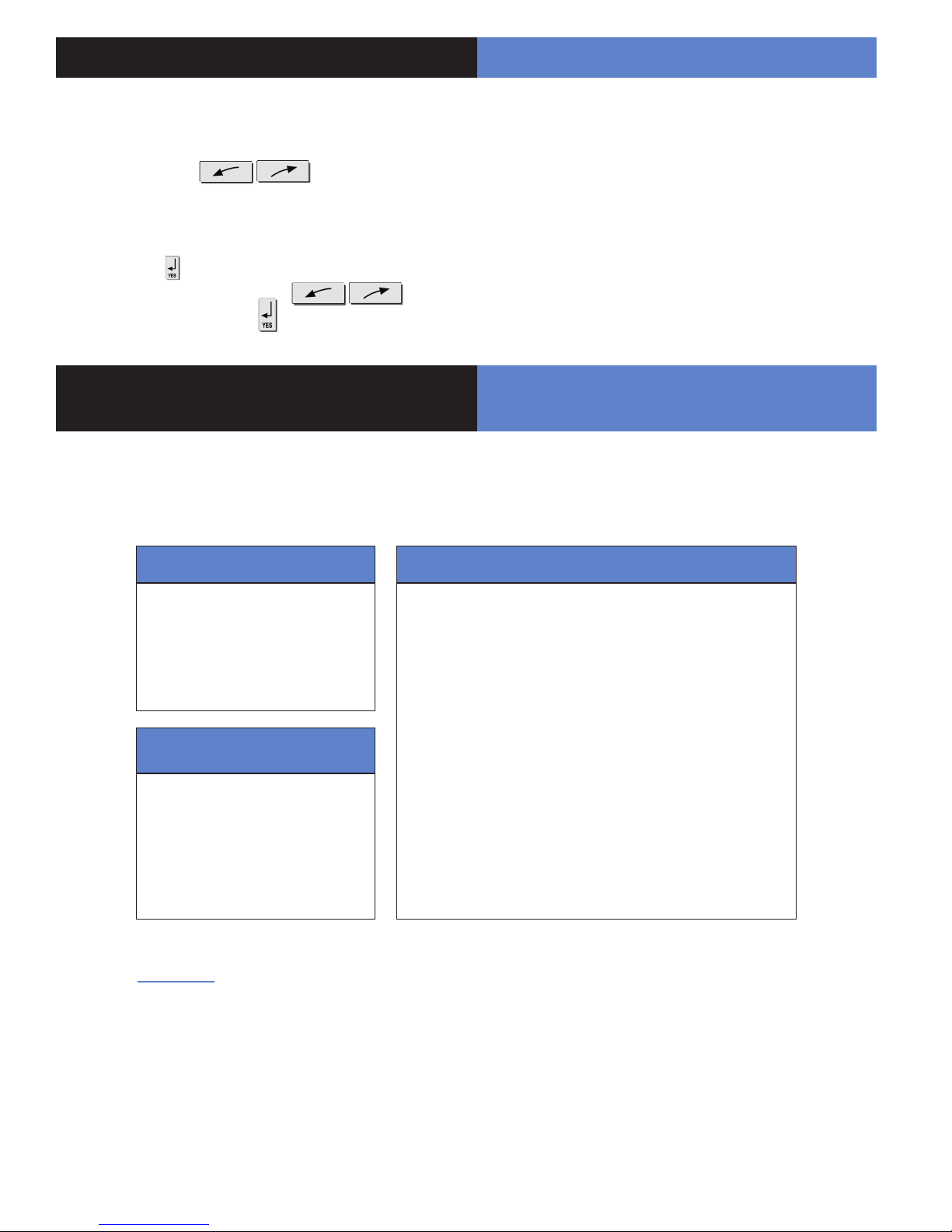
5.5 Program the arming modes profiles
With direction arrows go to the menu
CONFIGURATION (level 4 + installer code + [YES]) -> ALARM
MODES PROGRAMMABLE -> FULLY ARMED, MODE SP1,
MODE SP2 (use the direction arrows: right or left and [YES] to
select the alarm mode to be modied).
A rst screen will conrm the concerned areas by this mode.
Each time you press on N° of the concerned area, modies
the state of the correspondant situated below (validation by the
[YES]) key. Then select the alert type sound you want with the
direction arrow (Cf. diagram in the following page).
5. How to...
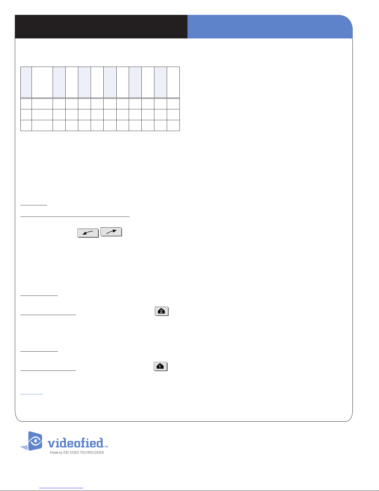
Areas : 1 2 3 4 Each time you press on the number
of the area it modies the correspondance.
State : A A A A Situated below. Validation at the end, the
[YES] key.
A Armed
D Disarmed
Perimeter
P
(all the opening
contacts)
External (opening
E
contacts protecting an
exterior access)
Siren
Delay
beeps
Silent
Without
siren
Immediate triggering
of all sirens
Entry/Exit delay
beeps, then triggering
of the sirens
Without siren
without beeps
Beeps on the
keypad only
6.8 Delete the Entry beeps report of the interior
sirens
When a interior siren is added, the delay beeps are automatically
sounded through it. It is possible to remove them from the menu :
CONFIGURATION (Access Level 4 + installer code + [YES]) ->
AREAS AND DEVICES -> DELAY BEEPS + [YES]. Chose the
inhibited state.
6.9 Reinitializing a panel
NOTICE : Re initializing the panel will clear any programming
Press 8 seconds on the PROGRAM Button of the panel (the
indicator should ash 2 times).
6.6 Deactivatethe panic button of the keypad (red
button)
With direction arrows go to the menu
PROGRAMMABLE FEATURES -> PANIC BUTTON
ENABLED Validate with the [YES] key. Use direction arrows to
modify the state. Validate with the [YES] key. Enter the installer
code if need to be in Level 3 or higher.
6.7 Re-engage the panel’s siren following the addition of an interior siren.
The addition of an interior siren will inhibite the panel siren, which
can however be reactivated.
To do this then go to the menu : CONFIGURATION (Access Level
4 + installer code + [YES]) -> AREAS AND DEVICES -> SIREN
PANEL + [YES]. Chose the authorized state.
REM : It is imperative to
leave the cover of the panel
open !
LED
Panel PROGRAM
BUTTON
6.10 Add a device after an initial configuration
With direction arrows go to the menu
CONFIGURATION (level 4 + installer code) -> AREAS AND
DEVICES. Validate by the [YES] key, DEVICES appears, press
on the [YES] key, ADD A DEVICE press on the [YES] key
PRESS PROGRAM BUTTON OF DEVICE record the device
by pressing on the PROGRAM BUTTON.
Be careful : If you add a device in a previously used area, it will
be necessary to modify arming modes (Cf. 5.5) in order to take
into account this new area only on versions pre v32.xx.
7
5. How to...
5.13 How to activate/deactivate the monitor
station?
With direction arrows go to the menu
CONFIGURATION (level 4 + installer code + [YES]) ->
CONFIGURATION MONITOR. STATION -> MONITORING
PARAMETERS -> MONITORING ?
Press on the key , then select the state that you want (active
or inactive) with the direction arrows
and nally validate with the key .
6. Details of the menu : ALARM CODES /
TR ANS STATE MODIFICATION
6.1 Signalling events by default (except if you are
using pre programming)
By default these events are transmited:
DEVICE (intrusions)
ALERT (button)
TAMPER
PERIODIC TEST
There are the 3 transmission
states:
ALARM, which can be heard :
when it appears
ALARM / END, which can be
heard : when it appears and disappears
NOT TRANSMITTED
Examples :
- If one wishes to recall events of ARMING/DISARMING (operate/stop), you will have to modify the
conguration of events ARMING/DISARMING to ALARM / END.
INITIALIZATION
PANEL BATTERIES (low panel batteries)
AC POWER (panel power off)
PHONELINE FAULT (telephone)
DEVICE BATT. (low batteries devices)
RADIO JAMMING (radio jamming)
SUPERVISION (default supervision)
WRONG CODES (when entering 5 false codes/badges)
DURESS CODE (panic button)
ALARM MEMORY (old memory overwritten)
ARM/DISARM (open/close)
By default are not transmited:
- If you wish to recall the false codes information, you will have to modify the conguration of events
WRONG CODES on the state ALARM.
6. Detail of the menu : AL ARM
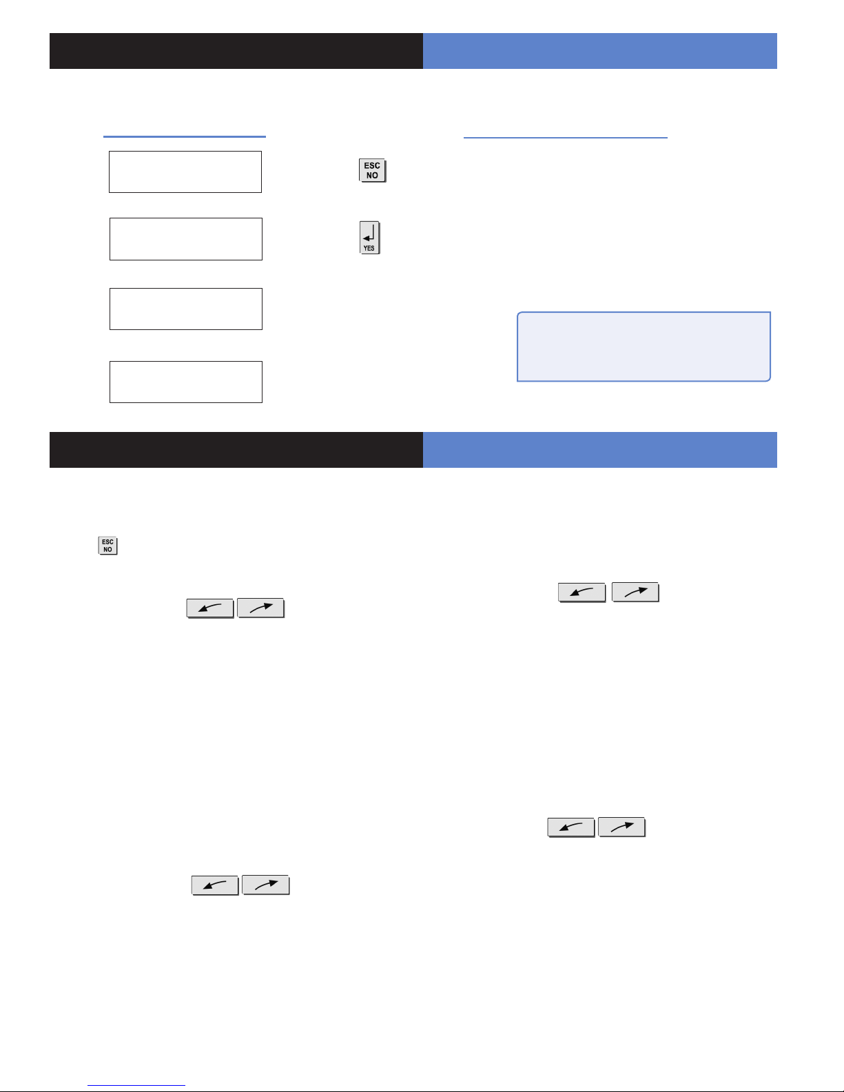
How to modify the transmission state of events?
This setting can be different from one panel to another.
It can be modified with the CODE/STATE MODIFICATION
menu.
2 possible solutions:
• At installation, just after having validated the hour of the
cyclic test, the keypad requests :
CODE/STATE
MODIFICATION ?
Press on the key to access
the menu TRANS. STATE
MODIFICATION
• After the initial installation, by using the keypad :
With direction arrows go to the menu
CONFIGURATION (level 4) -> CONFIGURATION MONITOR.
STATION -> ALARM CODES -> TRANS. STATE
MODIFICATION
Then:
With direction arrows Select the event to
transmit, make then modify the transmission state with
arrows and revalidate with the [YES] key. Renew the operation
for each event which you wish to modify the transmission
regulations.
6.2 Alarm code, default codes: (except if you are
using pre programming - Not available when the
format of FRONTEL is used)
How to modify associated alarm codes?
After having completed the installation by using the keypad :
With direction arrow go to the menu
CONFIGURATION (level 4) -> CONFIGURATION
MONITOR. STATION -> ALARM CODES -> ALARM CODE
MODIFICATION
Then:
With direction arrows select the device and
its associated code.
Press the key to modify the value.
Then enter the new value with the keypad and validate by
pressing the key .
Renew the operation for each device and associated code to be
modied, according to the regulations of your monitoring station.
EMEA SALES
2, rue Alexis de Tocqueville
92160 ANTONY
FRANCE
Hot line : +33 (0)820 846 620 / UK : 0871 951
Fax : +33 (0)3 90 20 66 36
www.vid e ofi ed.com
© 2009 RSI VI DEO TECHNOLOGIE S. VIDEOFIED
Specic ations subject to c hange without no tice.
TM
is a Registe red Trademark of RSI VI DEO TECHNOLOGI ES.
North American Headquarter
4455 White Bear Park way, Suite 700
White Bear Lake, MN 55110
USA
Hot Line : 877-206-5800
Fax : 651-762-4693
9

00
Security System Videofied
Made by RSI VIDEO TECHNOLOGIES Sept. 2009
® -
VISIO
Installation
data sheet
- Installation data sheet “Keypad”
- Installation data sheet “Indoor MotionViewerTM”
- Installation data sheet “Outdoor MotionViewerTM”
- Installation data sheet “Motion detector”
- Installation data sheet “Indoor siren”
- Installation data sheet “Outdoor siren”
- Installation data sheet “Remote control”
- Installation data sheet “Silent Panic Keyfob”
- Installation data sheet “Proximity Reader”
- Installation data sheet “Motion detector”
- Installation data sheet “Control relay”
- Installation data sheet “Synoptics of the menus”
- Installation data sheet “GPRS - Version 32 Panel”
- Installation data sheet “GPRS - Previous Version 32 Panel”
- Installation data sheet “XTENDER”
- Installation data sheet “New functionalities”
VISIO means V6000 for USA/Canada, V7000 for Australia/
Singapore and VISIO1000 for Europe and rest of the world.
EMEA Hotline: +33 (0)820 846 620 / UK : 0871 951
EMEA Hotline: 877-206-5800

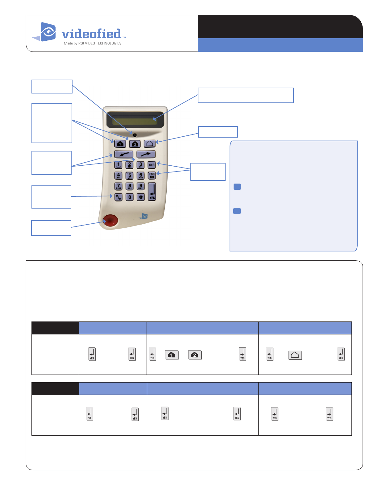
Indicator LED
Special Arming
Mode 1 and
Special Arming
Mode 2
Direction
arrows
Capital / Small
letter
Panic button
I N S T A L L A T I O N D A T A S H E E T
Mad e b y R SI VID EO TECH NOLOGIES
Display : 2 lines with 16 characters
Perimeter
Programming
Buttons
Keypad CMA
Recording of a keypad
The alarm panel must be put in "Recording device
mode", and the keypad must display “PRESS
PROGRAM BUTTON OF DEVICE”.
1
Insert the 3 batteries Lithium LS14500 (the
3 batteries are inserted in the same
direction)
Press simultaneously on [CLR] and
2
[ESC NO] of the keypad until the indicator
ofthekeypadashesandrelease
(possibility of testing the RF range).
1. Arming and Disarming
The keypad becomes inactive after 30 seconds of inactivity. To
revive the keypad you can press any key on the keypad. The
best button to press is the [YES] key because it will not trigger
an action.
Arming Fully Armed Special Mode 1 or 2 Perimeter
Keys of the
Keypad
Disarming Fully Armed Special Mode 1 or 2 Perimeter
Keys of the
Keypad
Code + + or + C o d e + + + Code +
+ Code + + Cod e + + Code +
To change from one arming mode to another, you have to
to fully disarm the system.
CMA means CMA600 for USA/Canada, CMA700 for Australia/
Singapore and CMA200 for Europe and rest of the world.
www.vid eofied.com
I N S T A L L A T I O N I N S T R U C T I O NKeypad CMA
2. Obtaining special characters
press
press
th
th
11
10
1
Key
st
“space”
press
press
press
th
1
2
. ,
press
th
th
4
3
‘ ? ! ; : # 1
press
press
th
5
press
th
th
7
6
press
press
th
th
8
9
0 - + = / ¥ _ < > ( ) 0
@ @ $ % & * #
REM : The other keys function as in writing SMS with a
>
cellular phone.
3. Initiating Panic Alerts
3.1 Red Button of the keypad
Panic alert : immediately triggers on all sirens.
Key order to activate/disactivate the function :
With direction arrows go to menu:
PROGRAMMABLE FEATURES -> PANIC BUTTON
ENABLED. Validate with the [YES] key. Use direction arrows to
modify the state.Validate with the [YES] key.
Enter the installer code if need be.
3.2 Silent Panic alert
On the keypad : Code under constraint (or under threat) : User
code + 1, example : (2999 -> 3000)
4. I have a problem, what should I do?
4.1 My first keypad does not record on the panel
Have you pressed on the PROGRAM BUTTON of the panel
before trying to record on the keypad?
4.2 Retrieve a keypad deleted by error
Remove the keypad's batteries.
Press the PROGRAM BUTTON of the panel for one second
(cover closed), (the indicator flashes once). Put back the batteries
and initialize the keypad by simultaneously pressing on the [CLR]
and [ESC NO] key unitl the indicator of the latter flashes and then
release. It will then require you to enter the installer code (do so
and validate with the [YES]) key, then the keypad is recovered.
4.3 How to fix a faulty keypad, without re-program-
ming the site
Press on the PROGRAM BUTTON of the panel for one second
(cover closed), the indicator flashes once.
Put the batteries in the new keypad.
Press the [CLR] and [ESC/NO] keys simultaneously unit its
indicator flashes and then release. The keypad records.
Key in the installer code again on the keypad's demand.
Possibility of testing RF radio range and out of this menu and the
new keypad is operational.
Proceed in carrying out in limited time of 15 seconds and renew
the operation if need be.
(Do not forget to delete the faulty keypad of the programming,
otherwise there will be a RF Supervision of radio loss…)
On the remote control : Press 2 seconds on the key
(acquisition bip for 2 seconds)
3.3 Audible Panic Alert
On the keypad : Code under constraint (or under threat) : User
code + 2, example : (2999 -> 3001)
On the remote control : Press 2 seconds on the key
(acquisition bip for 2 seconds)
Remark : If the red button of the keypad is deactivated, the alert
sound on the remote control will not function, but on the keypad
will still display that the panic has been pressed and will require
a code + [YES].
5. Add a second keypad
It is possible to add several keypads on the same site. During
the recording of a new keypad, it is possible to allocate to a
geographical zone other than zone 1, but in this case the new
chosen zone shall also be delayed.
CMA means CMA600 for USA/Canada, CMA700 for Australia/
Singapore and CMA200 for Europe and rest of the world.
EMEA SALES
2, rue Alexis de Tocqueville
92160 ANTONY
FRANCE
Hot line : +33 (0)820 846 620 / UK : 0871 951
Fax : +33 (0)3 90 20 66 36
www.vid e ofi ed.com
© 2009 RSI VI DEO TECHNOLOGIE S. VIDEOFIED
Specic ations subject to c hange without no tice.
TM
is a Registe red Trademark of RSI VI DEO TECHNOLOGI ES.
North American Headquarter
4455 White Bear Park way, Suite 700
White Bear Lake, MN 55110
USA
Hot line : 877-206-5800
Fax : 651-762-4693
Installation height of the pet immune camera :
Thedetectormustbexedwith
a screw, one of which must be
positioned in the tear-off zone
I N S T A L L A T I O N D A T A S H E E T
Mad e b y R SI VID EO TECH NOLOGIES
2m10 (6 1/2’) to the bottom of the camera
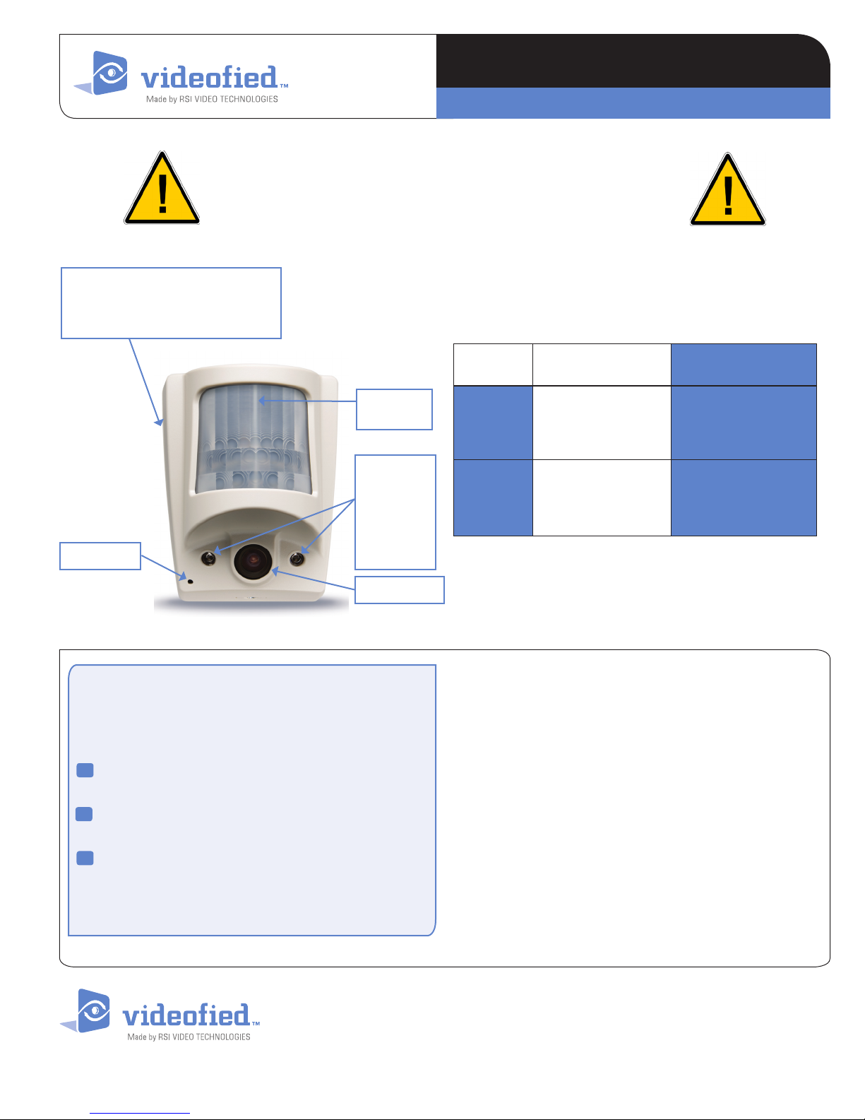
Indoor MotionViewer
DCV
TM
I n d i c a t o r
LED
Infrared
illuminators
for night
vision.
Objective of
INIT Button
the camera
Camera
Recording of the detector
The alar m pa nel mu st b e placed in “ Re cording device”,
mo de t he n and the key pad mu st d isplay“ PRE SS
PR OGR AM B UTTON O F DEV ICE ”.
Insert the 3 Lithium batteries LS14500 (in the same
1
direction).
2
Press the PROGRAM BUTTON of the detector,
releaseassoonastheindicatorashes.
Installation height
From 2m10 (6 1/2’) to
2m30 (7 1/2’) to the
bottom of the camera
Must imperatively be
2m10 (6 1/2’) to the
bottom of the camera
DCV200
DCV600
DCV700
DCVA200
DCVA600
DCVA700
Pet immune
NONE
YES 18 KG (40lbs)
> Possibility of testing the RF range.
> Possibility of testing the detection cover range.
* This indicator will no longer flash from then on except at
opening or during a detection test.
3
With the aid of the keypad, continue recording by
running the Radio Range Test and allocating an
area....
Always place the camera on an unobstructed angle.
DCV means DCV600 for USA/Canada, DCV700 for Australia/Singapore
and DCV200 for Europe and rest of the world.
EMEA SALES
2, rue Alexis de Tocqueville
92160 ANTONY
FRANCE
Hot line : +33 (0)820 846 620 / UK : 0871 951
Fax : +33 (0)3 90 20 66 36
www.vid e ofi ed.com
© 2009 RSI VI DEO TECHNOLOGIE S. VIDEOFIED
Specic ations subject to c hange without no tice.
TM
is a Registe red Trademark of RSI VI DEO TECHNOLOGI ES.
North American Headquarter
4455 White Bear Park way, Suite 700
White Bear Lake, MN 55110
USA
Hot line : 877-206-5800
Fax : 651-762-4693

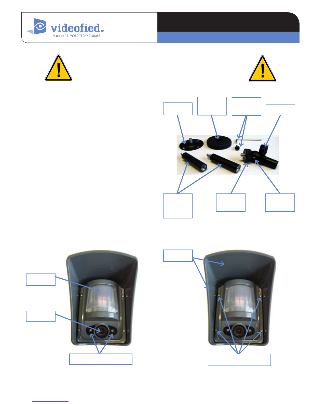
Outdoor MotionViewer
I N S T A L L A T I O N D A T A S H E E T
Mad e b y R SI VID EO TECH NOLOGIES
Installation height of the outdoor camera :
2m80 to 3m (9’ to 9 1/2’) to the bottom of the camera
TM
DCV
The outdoor MotionViewer detector DCV250/DCV650/
DCV750 is integrated with lters and analytical levels which
enables it from untimely triggering on with the presence of
small animals : rabbits, cats, birds.... However, dogs, foxes
and wild boars can be detected.
It is highly recommended to use a camera head kit (no Kodak
screw) or our MB100 camera kit to x the camera, indeed,
if you bore a hole in the lower stand of the camera, its
waterproofness will be lost...
Composition of the MB100 kit
- Base stand with screw cover.
- A camera head enabling a 360° orientation of the camera
with a wing screw (or Allen screw supplied with its key).
- Two extension cords - 5 cm each. Camera xing screw
(diameter 6.35 mm - 20 threads per inch).
Base
Extention
5 cm (2 1/2
inches)
Screw cover
for the base
Clamping
Screw + Allen
key Wing screw
ring
Ball pivot
360°
Indicator LED
Camera
Infrared LED for night vision
DCV means DCV650 for USA/Canada, DCV750 for Australia/Singapore
and DCV250 for Europe and rest of the world.
Base
Clamping screw for camera
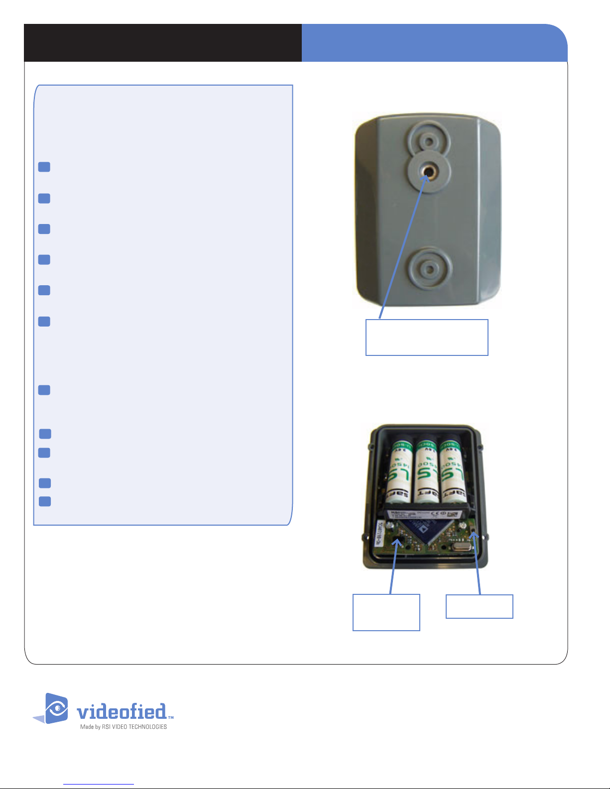
I N S T A L L A T I O N D A T A S H E E TOutdoor MotionViewerTM DCV
Recording of the detector
The alar m pa nel mu st b e pu t in " Rec or ding device
mo de", and the keypad m us t display“PRES S
PR OGR AM B UTTON O F DEV ICE ”.
Insert the 3 Lithium batteries LS14500 (in the same
1
directions).
2
Press the PROGRAM BUTTON of the camera
detector, release as soon as the indicator ashes.
3
Carefully place the block camera on its base
and screw down the 4 clamping screws.
4
Fix the base of the ball and socket head on a desired
height and place (while respecting xing height.
5
Place the screw cover on top and screw down the
ball pivot.
6
If need be, use extentions then screw them down
to the camera detector on the top of the ball and
socket head (or extentions) and screw down
the ring of the ball and socket head in order
guarantee adequate xing.
Back wall
Location of the ball pivot,
camera xing screw
7
Finally, direct the camera as required and tighten
with wing screw or Allen screw (to be used instead of
the wing screw).
Test the RF range (RSSI level at 20 seconds).
8
Allocate an area (with direction arrows of the keypad)
9
and validate with the [YES] key.
Name the device.
10
Test the detection coverage area.
11
> Possibility of testing RF cover (minimum radio level at 20).
> Possibility of testing the detection cover range.
* This indicator will no longer flash from then on except at
opening, arming or during a detection test.
DCV means DCV650 for USA/Canada, DCV750 for Australia/Singapore
and DCV250 for Europe and rest of the world.
Camera block
Self protection
of the camera
Program Button
EMEA SALES
2, rue Alexis de Tocqueville
92160 ANTONY
FRANCE
Hot line : +33 (0)820 846 620 / UK : 0871 951
Fax : +33 (0)3 90 20 66 36
www.vid e ofi ed.com
© 2009 RSI VI DEO TECHNOLOGIE S. VIDEOFIED
Specic ations subject to c hange without no tice.
TM
is a Registe red Trademark of RSI VI DEO TECHNOLOGI ES.
North American Headquarter
4455 White Bear Park way, Suite 700
White Bear Lake, MN 55110
USA
Hot line : 877-206-5800
Fax : 651-762-4693
 Loading...